
K-WANG


SIEMENS SINAMICS S120 Driver
SIEMENS SINAMICS S120 Driver
SINAMICS S120 Overview
core components
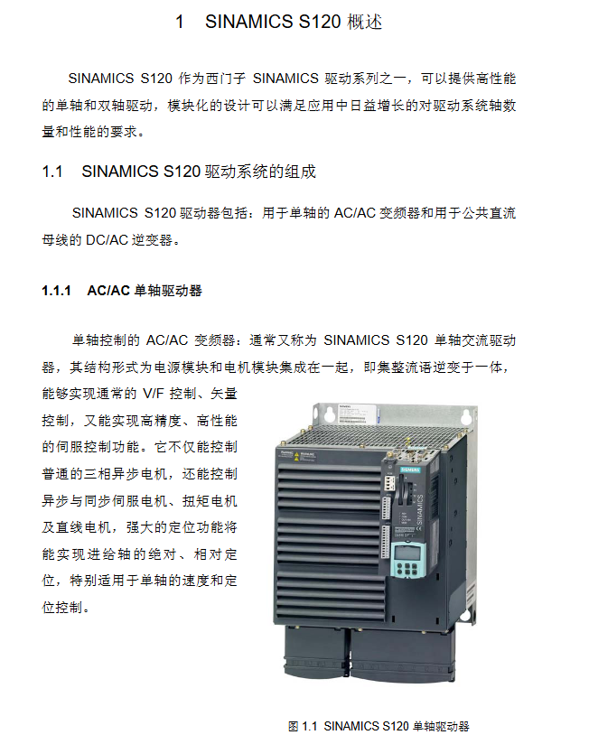
AC/AC single axis driver: power supply+motor module integration, CU310 DP/PN+PM340, Supports multiple types of motors, suitable for single axis speed/positioning control;
DC/AC multi axis driver: The power supply and motor module are separated and connected through the DRIVE CLiQ high-speed interface. The core is CU320, which also includes power module, motor module, sensor module, etc. It is suitable for multi axis industries (paper/packaging, etc.) and can share energy between axes.
CU320 control capability: maximum speed control of 6 servo axes/4 vector axes/8 V/F axes; The maximum position control is 4 servo axes/2 vector axes. Servo and vector axes cannot be mixed and can be paired with V/F axes.
Power module classification: Basic type (BLM, no feedback), Intelligent type (SLM, feedback+non adjustable bus voltage), Active type (ALM, feedback+adjustable bus voltage).
Indicator lights: CU320, ALM/SLM rectifier module, and motor module are all equipped with LED indicator lights, which reflect equipment operation faults through color/status. If the RDY light of CU320 is always red, it indicates a fault and needs to be cleared before restoration.
Experimental equipment: Based on a 230V input line, it includes CU320 with TB30, 5kW SLM, 3A dual axis motor module, 2 1FK7 synchronous motors, SMC20 encoder module, and Control Box operation box.
SINAMICS S120 Project Configuration
Before configuration, a PC with SCOUT software and DP communication card needs to be prepared to complete the hardware connection. The DP address can be set through binary switch (ON=2 ⁿ, n starts from 0) or P0918 parameter setting (when the switch is fully ON/OFF), supporting both offline and online configuration methods. After configuration, the data needs to be downloaded from RAM to ROM (CF card) for power-off saving.
Offline configuration: Suitable for motors without DRIVE CLiQ interface. The steps are to create a new project → DP communication port setting → drive unit (power/motor/encoder) configuration → project download and storage. When configuring, the control mode (vector/servo) must be selected, and a CU320 cannot be configured with both vector and servo axes simultaneously.
Online configuration: Suitable for Siemens motors with DRIVE CLiQ interface. The steps are: create a new project → DP settings → online connection → restore factory settings → automatic configuration → offline replenishment without DRIVE CLiQ components → download and store. If the firmware version is low, it will be automatically upgraded (3-4 minutes).
Basic debugging
Before debugging, it is necessary to confirm that the project topology is consistent with the actual hardware and supports three basic control methods: control panel, operation box, and BOP20. At the same time, the dynamic characteristics of the motor can be debugged through the Scout tool.
Control panel control: Select axis → Obtain control → Enable axis → Set speed → Start stop, switch axis requires relinquishing control first.
Operation box control: It is necessary to insert the TB30 option board into CU320 and wire it, control the start/stop/reset through digital input (DI), set the speed through analog input (AI), and complete the parameter correspondence between CU320/TB30 and the operation box (such as DI0 corresponding to r0722.0).
Basic operation panel of BOP20: with 6 buttons and background light, it can realize parameter modification, motor start stop, fault reset, support hot plugging, core parameters such as p0003 (access level) and p0008 (transmission object selection), long press the P key for 3 seconds to execute Copy RAM to ROM.
Debugging of motor dynamic characteristics
Trace function: measure time-domain curves such as speed/current, set trigger mode, and analyze overshoot and other issues through curve analysis;
Function generator: Set the forward and reverse rotation of the motor and record the dynamic response curve;
Measuring function: only applicable to servo control, measuring frequency domain Bode plot, optimizing by adjusting proportional gain/integration time, requiring amplitude margin>12dB and phase margin 30-60 °.
Motor optimization
Starting from FW V2.4, motor optimization is supported for Siemens/third-party induction motors and synchronous servo motors, including automatic optimization and manual step-by-step optimization. Before optimization, it is necessary to ensure that the motor is in a cold state, the brake is disconnected, and the mechanical system is safe.
Automatic optimization: Execute Automatic controller setting in Scout to complete motor data calculation and static/dynamic optimization. After optimization, parameters need to be accepted and saved. The overshoot of the motor is significantly reduced after optimization.
Induction motor optimization (vector/SLVC mode)
Step parameter function notes
1. Nameplate parameters (p304/p305, etc.) require input of rated voltage/current/power for motor basic data configuration
2 P340 motor data calculation (fixed/rotor impedance) without enabling frequency converter
3 P1910 Static identification (stator/rotor impedance, leakage inductance, etc.) needs to be enabled, and the motor may rotate 90 °
4 P1960 dynamic identification (encoder testing, speed loop optimization, inertia calculation) is optimized separately under no-load/load conditions, which requires enabling
Optimization of servo motor
The basic steps are the same as induction motors, with the core difference being that dynamic identification requires P1959+P1960 coordination, while static identification may require the motor to rotate 210 °. No load/load optimization requires adjusting the ramp time, current/speed limit according to actual conditions.
Basic positioning
FW V2.4 HF2 and above versions support basic positioning functions, and debugging software needs to be Scout/S120 V4.0+and STEP7 V5.3.3.1+, which need to be activated in offline configuration. It includes 5 core functions and supports control panel/expert parameter table settings.
Activation condition: After configuration, confirm that r108.3=1 and r108.4=1, and the Technology/Basic locator will appear in the project navigation bar.
core functionality
Jogging: divided into speed mode (press button to run, release button to stop) and position mode (automatically stop when running to the target position), require enabling ON/OFF 1 (P840) first;
Zeroing: The incremental encoder needs to be zeroed, while the absolute value encoder only needs to be initialized and calibrated once. There are three methods: setting a reference point (setting the origin at any position), active zeroing (incremental only, three ways), and passive zeroing (dynamic zeroing, which does not affect operation);
Limit: including soft limit (P2582 activated, P2578/2579 set range) and hard limit (P2568 activated, fault stops upon arrival, only reverse operation is allowed), which can limit speed/acceleration;
Program steps: up to 64 steps, supporting automatic continuous/single step execution, with digital input switching between steps;
MDI: Divided into position mode (absolute/relative) and velocity mode, data transmission supports single step (along effective) and continuous (only absolute position, real-time modification).
Parking methods: ON/OFF 1 (normal parking), OFF 2 (free parking), OFF 3 (quick parking, emergency use).
Communication function
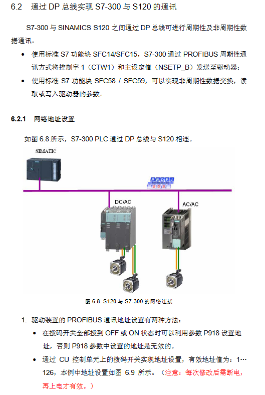
S120 supports two communication methods: direct communication with HMI and communication with S7-300 through DP bus, both of which require DP address settings to be completed first. Communication is divided into two forms of data exchange: periodic and non periodic.
S120 communicates directly with HMI: without the need for a PLC, implemented through WinCC flexible. The steps are DP address setting → Step 7, insert HMI Station and configure it → establish a variable table. The variable table DB/DBW follows the rule of DBW=1024 x device number+parameter index number.
S7-300 communicates with S120 DP bus
Message configuration: Common messages such as 370 and 999 (custom), SERVO axis supports 2/3/7 messages, VECTOR axis supports 1/2/20 messages, etc;
Periodic communication: Motor start stop and speed control are achieved through SFC14 (read)/SFC15 (write), with control word Bit0 controlling start stop. The main set value of 4000H corresponds to 100% speed;
Non periodic communication: Drive parameter reading and writing are achieved through SFC58 (write)/SFC59 (read). Based on DPV1 function, up to 240 bytes of data can be exchanged, and the response contains an error code (such as 0x02 indicating parameter value exceeding the limit).
DCC function
DCC (Drive Control Chart) is a graphical CFC programming tool developed by Siemens for SINAMICS/SMOTION. It supports FW V2.5x/SCOUT V4.1x and above, and implements functions such as logic, computation, and closed-loop control.
Core components: DCC editor (CFC programming)+DCC function library (SINAMICS/SMOTION library), divided into DCC-SIMOTION (P/C/D) and DCC-SINAMICS (S120).
Basic functions: logical operations, arithmetic operations, data type conversion, closed-loop control, process functions, system functions.
Configuration compilation process: Add process package → Import library file → Offline programming and allocation of execution group sampling period → Compile and download → Run and debug.
Key points to note
The execution component is fixed/free, and the free execution group sampling period P21000 is 1ms~r21003, which is an integer multiple of the hardware/software sampling time;
DCC will increase the load on CU. The CU for performance 1 requires r9976 average/maximum value to be ≤ 85%. If it exceeds 90%, A50512 alarm will be triggered;
Parameters are divided into direct assignment type (@+number) and BICO type (@ *+number), with BICO type enabling parameter interconnection.
Experimental demonstration: Generate sine and cosine curves through an integrator, associate them with the speed setting parameter P1155, and achieve motor speed variation according to the curve. The maximum speed can be limited by P2900.
- YOKOGAWA
- Reliance
- ADVANCED
- SEW
- ProSoft
- WATLOW
- Kongsberg
- FANUC
- VSD
- DCS
- PLC
- man-machine
- Covid-19
- Energy and Gender
- Energy Access
- Renewable Integration
- Energy Subsidies
- Energy and Water
- Net zero emission
- Energy Security
- Critical Minerals
- A-B
- petroleum
- Mine scale
- Sewage treatment
- cement
- architecture
- Industrial information
- New energy
- Automobile market
- electricity
- Construction site
- HIMA
- ABB
- Rockwell
- Schneider Modicon
- Siemens
- xYCOM
- Yaskawa
- Woodward
- BOSCH Rexroth
- MOOG
- General Electric
- American NI
- Rolls-Royce
- CTI
- Honeywell
- EMERSON
- MAN
- GE
- TRICONEX
- Control Wave
- ALSTOM
- AMAT
- STUDER
- KONGSBERG
- MOTOROLA
- DANAHER MOTION
- Bentley
- Galil
- EATON
- MOLEX
- Triconex
- DEIF
- B&W
- ZYGO
- Aerotech
- DANFOSS
- KOLLMORGEN
- Beijer
- Endress+Hauser
- schneider
- Foxboro
- KB
- REXROTH
- YAMAHA
- Johnson
- Westinghouse
- WAGO
- TOSHIBA
- TEKTRONIX
- BENDER
- BMCM
- SMC
- HITACHI
- HIRSCHMANN
- XP POWER
- Baldor
- Meggitt
- SHINKAWA
- Other Brands
- UniOP
- KUKA
- IBA
- Beckhoff
-
Basler Electric DECS-250-CN1SN1N Automatic Voltage Regulator for Generator Excitation Control
-
ADLINK CPCI-6860A - 51-31310-OB10 industrial motherboard CompactPCI SBC
-
ADLINK AmITX-SL-G-H110 - 51-7A104-0A30 Mini-ITX Industrial Motherboard
-
ADLINK PXI-2005-003 - CPCI Industrial PC Data Acquisition Card Multi-Function DAQ
-
ADLINK DININ-814M - 51-14032-0A3D SCSI-100P cable connection Interface Terminal Board
-
ADLINK CPCI-3920NA/C2D15/M1G - 3U CompactPCI Intel Core 2 Duo Single Board Computer
-
ADLINK PCIE-8560 - 51-18014-0A20 Communication Card High Speed DAQ
-
ADLINK PCI-C154+ - Motion Control Card 4-axis Motion Controller Board
-
ADLINK PCI-RTV24 - image capture card Analog Video Frame Grabber
-
ADLINK NuPRO-842LV/P - 51-41360-0B30 Industrial Motherboard CPU Board
-
ADLINK cBP-3208/3208R - CPCI Board 3U 8-Slot CompactPCI Backplane
-
ADLINK PCI-8164 - 4-Axis Motion Controller PCI Card 51-12406-0A40
-
ADLINK PCIe-GIE64+ - 4-CH GigE Vision PoE+ Frame Grabber Video Capture Card
-
ADLINK CPCI-6860 / 6860A - CompactPCI Dual Xeon Single Board Computer
-
ADLINK IEC-915GV - REV 1.1 Industrial motherboard CPU Board
-
ADLINK ND-6520 - Technology RS-232 to RS-422RS-485 Converter NuDAM Module
-
ADLINK RTV-24 / PCI-MP4S - 51-12519-1C30 4-Channel Real Time Video Capture Board
-
ADLINK cPCI-6910 / cPCI-6910AM/M1G - cPCI-6910AM/DXL16/M1G/S80G(G)-3120 BOARD CompactPCI SBC
-
ADLINK NUPRO-A40H - Linghua 51-41807-1A30 Industrial Control Computer Motherboard
-
ADLINK USB-3488A - USB to GPIB INTERFACE USB-3488A(G) Controller Module
-
ADLINK PCI-8134A - motion control card 4-Axis Controller Card
-
ADLINK PCI-7432 - Board 32-Channel input / 32-output Isolated Digital I/O PCI Card
-
ADLINK PCI-8134A - 51-12421-0A10 motion controller card tested
-
ADLINK LPCIe-7230 - 32 CH Isolated Input/output Card 2 Interrupts Low Profile PCIe
-
ADLINK NuPRO-E340 - industrial computer motherboard 51-47807-0A30 PICMG 1.3 SHB
-
ADLINK PCI-7434 - High-speed Digital Acquisition Card 64-CH Isolated DO Card
-
ADLINK NuPRO-E330 - 51-41805-0A20 Indsutrial Board SHB Single Board Computer
-
ADLINK PCI-7248 - OPTO-22 48 CHANNEL DIO DIGITAL TTL/DTL I/O 51-12006-0A40 GP
-
ADLINK PCI-8134 - Motion control card 4-Axis Controller Card
-
ADLINK AMP-208C - Movimiento Control Tarjeta 51-12420-1A20 W/Expansión & Breakout
-
ADLINK PCI-8164 - 51-12406-0A40 PCB Board 4-Axis Motion Controller Card
-
ADLINK DIN-68Y-SGII / DIN-68M-J3A - Terminal Board Connector Interface Block
-
ADLINK PCIe-7432 - Technology 51-18402-0A10 PCIe Card With High Input Range
-
ADLINK PCI-8144 / PCI-8144N - Motion control card 4-Axis Stepper Controller Card
-
ADLINK HSL-HUB3/REPEATER - HIGH SPEED LINK EXTENSION MODULES Distributed Hub Module
-
ADLINK ND-6017 - Data Logging + Acquisition 8CH A/D input Mod NuDAM Module
-
ADLINK LPCIe-7250 - data acquisition card Low Profile 8-CH Relay Output Card
-
ADLINK PCI-7432 - I/O card 64-CH Isolated Digital Input Output PCI Card
-
ADLINK IMB-M43H - industrial control computer motherboard Q87 Chip Micro-ATX
-
ADLINK MP-C154 - Motion control Card 4-Axis Motion Controller Board
-
ADLINK PCI-RTV24 - image capture card Video Frame Grabber Card
-
ADLINK PCI-7250 - 8-CH Relay Output & 8-CH Isolated DI Card
-
ADLINK PCI-6308V - 8-CH 12-Bit Isolated Analog Output PCI Card PCB-I-E-1148=6EX2
-
ADLINK PCI-7248 - capture card 48-CH Opto-22 Compatible DIO Card
-
ADLINK HSL-AI16A02-M-VV - Analog Input Output Distributed Module
-
ADLINK NuPRO-A301 - Rev:1.4 NUPRO-A301 PICMG Full-Size Single Board Computer
-
ADLINK PCI-6208V-GL - 8-CH Voltage Analog Output PCI Card
-
ADLINK PCI-8134A - 51-12421-0A10 4-Axis Motion Controller Card
-
ADLINK MNET-S23 - TECHNOLOGY MNET S23 - SERVO DRIVER CONTROL MODULE
-
ADLINK M-342 - ATX I3 I5 I7 Q67 Industrial Motherboard
-
ADLINK NUPRO-780 - Industrial Motherboard CPU Board PICMG SBC
-
ADLINK MP-C154 / MP-C152 - 4-Axis Motion Control Card Pulse-Train Controller
-
ADLINK NuPRO-935A/LV10B0 - Motherboard 51-41802-0A10 GP w/RAM Industrial Control Board
-
ADLINK MP-C154 - Motion control card 4-Axis Motion Controller Mainboard
-
ADLINK PCI-7250 - PCI Acquisition Card 8-CH Relay Output Isolated DI Card
-
ADLINK ACL-7124 - Technology Inc.24 DIO Card Digital Input Output Card
-
ADLINK PCI-8554 A2 - Timer/Counter Data Acquisition Card
-
ADLINK DIN-825-GP4 - Terminal Block Interface Board Breakout Module
-
ADLINK NuPR0-761 - REV:1.1 Industrial motherboard Full-Size PICMG SBC
-
ADLINK MXE-1401/M8G (G) - Matrix Fanless Embedded Computer Industrial PC
-
ADLINK HSL-DI16DO16-UD-NN - Digital 16 Channel I/O Mod Distributed I/O Module
-
ADLINK ND6520 - NUDAM INTELLIGENT DA&C MODULE RS232-RS-422/RS485 CONVERTOR
-
ADLINK NUPRO-761 - REV:1.1 Industrial Motherboard CPU Board
-
ADLINK AMP-208C - Motion Control Card 51-12420-1A20 DSP-based 8-axis
-
ADLINK NuPRO-A301REV 1.4 - with packaging industrial computer motherboard PICMG SBC
-
ADLINK PCM-9112+ - 51-12300-0A2 industrial motherboard Multi-Function DAQ PC/104 Module
-
ADLINK PCM-7250+ - 8-CH Relay Outputs & 8-CH Isolated DI Module PC/104
-
ADLINK PCI-RTV24 - Image capture card Analog Video Frame Grabber
-
ADLINK PCI-8134 - Motion Controller PCI Card 4-Axis Controller Board
-
ADLINK PCI-7432 - Isolated Digital I/O PCI Card
-
ADLINK PCI-8554 A2 - acquisition card Timer/Counter Card
-
ADLINK PCI-8132 - Rev.A2 2-Axis Servo & Stepper Motion Controller Card
-
ADLINK PCI-8132 - Data Acquisition card 2-Axis Motion Controller Card
-
ADLINK EBP-13E4 - 51-46703-0A30 Industrial Backplane Board Passive Backplane
-
ADLINK PCI-800L - Electronic Card Interface Controller Card
-
ADLINK PCIe-GIE72 - 51-18531-0A10 PCB Board GigE Vision Frame Grabber
-
ADLINK DAQ-2010(G)-OOBO - Simultaneous-Sampling Multi-Function DAQ Card
-
ADLINK PCI-9112 - REV.B1 Multifunction DAQ Card Data Acquisition Card
-
ADLINK PCI-7230 - 51-12003-DA60 32-CH Isolated Digital I/O Card
-
ADLINK PCI-7432 - Data Acquisition Card Isolated Digital I/O PCI Card
-
ADLINK ETX-AT-N270-18/LXE - 51-71111-0A20 ETX CPU Module Motherboard
-
ADLINK HSL-DI32-UD-N - DIGITAL INPUT 32 POINTS MODULE Distributed I/O
-
ADLINK AMP-204C - Motion Control card DSP-Based 4-Axis Advanced Controller
-
ADLINK MNET-4XMOG-0050 - Four-axis Motion Controller Distributed Motion Module
-
ADLINK AMP-204C - Motion control card DSP-Based 4-Axis Pulse-Train Controller
-
ADLINK PCI-7442 - Switch card 64-Channel Datalogging & Acquisition Card
-
ADLINK M-302 - Industrial control motherboard ATX PC Board
-
ADLINK NUPRO-852 / NUPRO-852LV - Industrial motherboard Single Board Computer
-
ADLINK PCI-8134 - REV.B1. 4-Axis Motion Controller Card
-
ADLINK PCI-GIE62 + - 51-18502-0A20 2-CH GigE Vision Frame Grabber PoE Card
-
ADLINK PCI-MPG24 - 51-12523-0B20 MPEG4 Card Video Compression Hardware
-
ADLINK HSL-TB32-M-DIN - 32-CH I/O TERMINAL W/ HSL-AI16AO2-M-VV MODULE
-
ADLINK PCI-M114-GL - PCB Ver 2.1 Motion Controller Axis Card
-
ADLINK IMB-M40H - SYM76996H61 motherboard Industrial Computer Mainboard
-
ADLINK NUPRO-A40H - 51-41807-1A20 industrial control motherboard H61 Chip
-
ADLINK PCI-M114-GL - Axis Card Data Acquisition Card PCB VER2.2 Motion Controller
-
ADLINK PCI-8134 - Motion Controller PCI Card 4-Axis Controller Board
-
ADLINK PCI-8102 - Motion control card 2-Axis Servo & Stepper Controller
-
ADLINK NuPRO-841REV:3.0 - motherboard Industrial Control PC Board
-
ADLINK HSL-TB32-U-DIN REV A1 - Breakout Terminal Board Field I/O Module
-
ADLINK AMP-204C - Motion Control card DSP-Based 4-Axis Pulse-Train Controller
-
ADLINK NUPRO-A40H - 51-41807-1A20 industrial control motherboard H61 PC Board
-
ADLINK PCI-6308A / PCI-6308V - 51-12202-0A50 Isolated Analog Output Card
-
ADLINK AMP-204C - DSP-Based 4-Axis Advanced Pulse-Train Motion Controller
-
ADLINK PCI-7434 - Technology 64-Channel Isolated Digital I/O PCI Cards
-
ADLINK CPCI-6840 / CPCI-6840V / PM16/M1G-12G0 - CompactPCI Single Board Computer CPU Module
-
ADLINK PCIE-GIE74 - Motherboard Video Capture Card 51-18531-0A10 Frame Grabber
-
ADLINK NuPRO-E330 - industrial computer equipment motherboard Control Mainboard
-
ADLINK AMP-208C / 51-12420-1A20 - Motion Control Card W/ Expansion & Breakout Board
-
ADLINK HPCI-14S12U - industrial computer baseboard Passive Backplane 14 Slots
-
ADLINK PCI-8164 - 4-Axis Motion Controller PCI Card W/ 1x Cable, 1x Breakout Box
-
ADLINK PCIe-RTV24 - 51-18016-0A20 Image Acquisition Video Capture Card
-
ADLINK M-342 - 5 PCI ATX Motherboard Industrial PC Mainboard
-
ADLINK PCI-FIW64 - 4/2 Channel IEEE1394B Image Capture Card FireWire Frame Grabber
-
ADLINK PCI-7432 - digital IO card 64-CH Isolated Digital Input Output Card
-
ADLINK 51-12001-0C20 - Circuit Board PCI-7200 Data Acquisition Controller Card
-
ADLINK PXI-3920 - PXI 3U cPCI Industrial Controller Embedded System CPU Board
-
ADLINK NuPRO-841REV:2.0 - motherboard Industrial Control PC Board
-
ADLINK NuPro-E330 - 51-41805-0A20 PCB Industrial Control Computer Motherboard
-
ADLINK PCI-RTV24 - Image capture card Analog Video Frame Grabber
-
ADLINK PCI-7442 - Switch card 64-Channel Datalogging & Acquisition Card
-
ADLINK HPX-13S4 - device baseboard Passive Backplane Riser Card
-
ADLINK PCI-9112 REV A.1 - Multi Function DA&C Board Data Acquisition Card
-
ADLINK PCI-7248 - 51-12006-0A40 Card Control 48-CH Digital I/O Module
-
ADLINK CPCI-6860 / 6860A - motherboard CompactPCI Dual Xeon Single Board Computer
-
ADLINK DPAC-3020-11(G) - Embedded PC Automation Controller Machine Control Board
-
ADLINK NuPRO-841 REV:1.0 - industrial control motherboard CPU Board
-
ADLINK MNET-4XMOG-0050 - Four-axis Motion Controller MNET Motion Control Card

K-JIANG

Add: Jimei North Road, Jimei District, Xiamen, Fujian, China
Tell:+86-15305925923