
K-WANG


SIEMENS SIMATIC Drive Controller System
SIEMENS SIMATIC Drive Controller System
Basic Framework and Security Standards
1. Positioning and safety warning
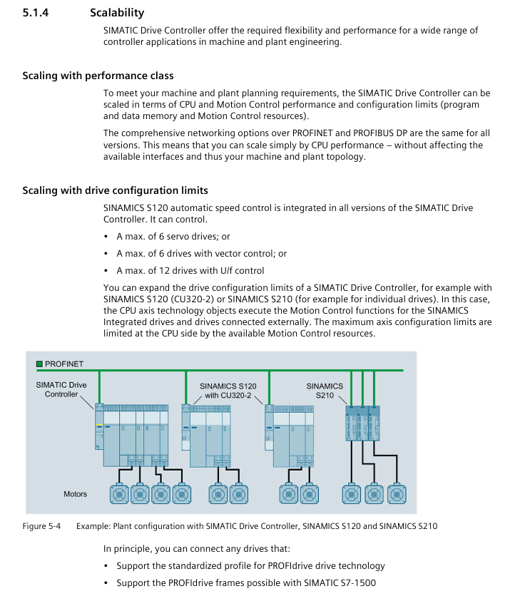
Scope: Covering the entire range of SIMATIC Drive Controllers, including CPU 1504D TF/1507D TF and SINAMICS Integrated, providing full process guidance from planning to maintenance, suitable for Motion Control scenarios such as multi axis machine tools, packaging machinery, printing equipment, etc.
Security level classification:
Warning type risk description example scenario
DANGER Fatal/Serious Personal Injury Contact with Live Parts, Undischarged Capacitors
Warning: May cause fatal/serious injury. Equipment damage may lead to electrical leakage, and wireless devices may interfere with safety functions
CAUTION Minor personal injury, electrostatic discharge damage to components
NOTICE property loss, wiring error leading to module failure
Qualification requirements: Only personnel with "industrial automation qualification" are allowed to operate, and they must be familiar with standards such as IEC 61131-2 and EN 60204.
2. Industrial network security (new core chapter added)
Protection strategy: Adopting the "Defense in Depth" framework, divided into 3 layers of protection:
Physical security: Lock the control cabinet door and manage access permissions (password/fingerprint)
Network security: network segmentation, firewall VPN、 Disable unused ports (such as NTP/PUT/GET)
System integrity: firmware updates, configuration verification, data backup
Key measures:
Regular firmware updates (via TIA Portal/memory card/web server)
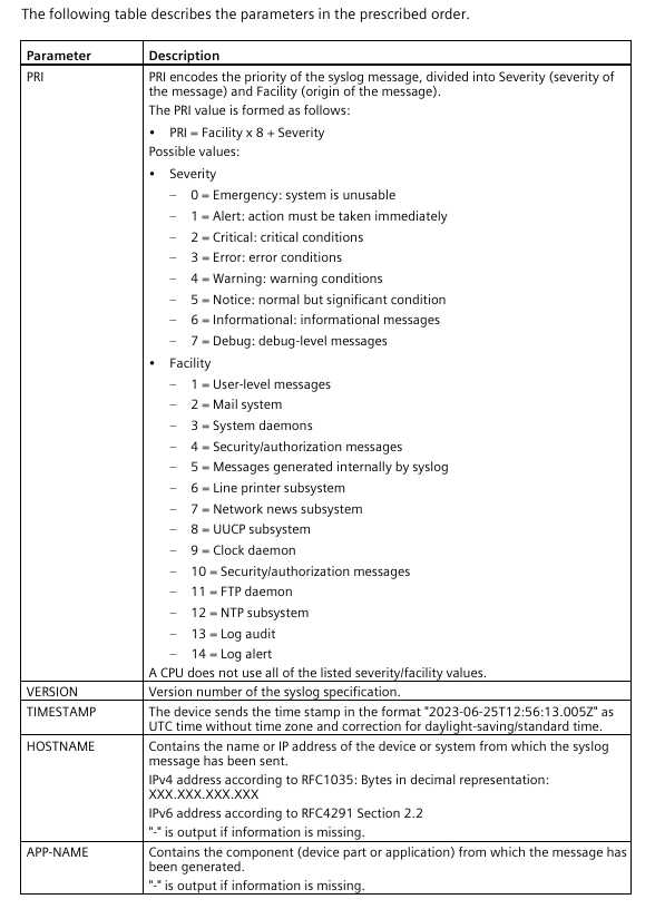
Syslog log: CPU local cache security events (such as password errors, configuration tampering) can be forwarded to the server (UDP port 514/TLS port 6514)
Data destruction: Before retiring the device, a "factory reset" (SINAMICS first, CPU later) must be performed to format the storage card or physically destroy it
System Overview and Core Components
1. Comparison of Core Parameters of Controllers
Component model: CPU 1504D TF (for small and medium-sized applications) CPU 1507D TF (for high-end applications) Key differences
Code working memory 4 MB 15 MB 1507D supports more complex programs
Data working memory 6 MB 40 MB 1507D can store more real-time data
Number of positioning axes (maximum) 40 160 1507D Supports multi axis synchronization
Motion Control resources 3200 12800 1507D handle higher loads
Minimum cycle 500 μ s 250 μ s 1507D supports higher real-time performance
Integrated I/O 8 DI/DQ (X142) 8 DI/DQ (X142) Consistent
2. SINAMICS Integrated Function
Control mode:
Servo control: Maximum dynamic response, supports Dynamic Servo Control (DSC, 125 μ s cycle)
Vector control: maximum torque accuracy, 250 μ s current controller cycle
U/f control: suitable for fan/pump loads, 500 μ s cycle
Security function:
Basic functions: STO (Safe Torque Shutdown), SS1 (Safe Stop 1)
Extended functions: SS2 (Safety Stop 2), SBC (Safety Braking Control)
Advanced features: SLS (Safety Speed Limit), SLA (Safety Distance Limit), requiring 1 license per axis
Restrictions: Free Function Blocks (FBLOCKS) and SIMOTION CX32-2 extensions are not supported, only partial technical extensions (such as POLYGON/SETPGEN) are supported
Application planning and installation wiring
1. Hardware configuration rules
Power configuration:
System power supply: 24V DC PELV (such as SITOP smart), no-load current 1.7A, maximum load 13.1A
Drive power supply: SINAMICS Line Module (generates DC link voltage), Motor Module takes power from the DC link
Communication configuration:
PROFINET IO IRT (X150): Supports isochronous mode, IRT level, synchronous multi drive
PROFIBUS DP (X126): Maximum of 12 I/O modules, does not support isochronous coupling
DRIVE CLiQ: 4 interfaces, each with 450mA power supply, connected to Motor Module/Encoder/Sensor Module (SMC)
2. Installation and wiring specifications
Installation requirements:
Guide rail: TH 35 standard guide rail (length 160-2000mm), fixed with M6 screws (torque 6Nm)
Gap: Top/bottom ≥ 80mm (heat dissipation), vertical installation (only allowed in the vertical direction)
Wiring rules:
Interface type wiring requirements, wire specifications
24V DC power supply 4-pin connector, distinguishing L+/M, stripping length 7-8mm 0.25-2.5mm ² (multi strand without sleeve)
PROFINET uses FastConnect cable, requires 8-core wire for 1000Mbps, and the 145 ° connector only supports 100Mbps CAT5e and above
DRIVE CLiQ shielded cable, the shielding layer is grounded through a metal bracket, with a maximum length of 100m Siemens specific DRIVE CLiQ cable
Digital I/O (X142) 24V DC, DI input delay 1 μ s/125 μ s, DQ high speed output (0.4A) Stripping length 10-11mm 0.25-1.5mm ²
Configuration and Debugging Process
1. Software configuration (TIA Portal+Startdrive)
Basic steps:
Create a project and add a Drive Controller (automatically generating CPU and SINAMICS Integrated devices)
Hardware configuration: Assign PROFINET device name/IP, configure SINAMICS driver object (Line Module/Motor Module)
Message configuration: default PROFIdrive message 393 (X122/X132 I/O), 105 (drive shaft)
Technical object configuration: Create positioning axis/synchronization axis/output cam, bind Drive Controller I/O (such as X142 Timer DI/DQ)
Isochronous mode configuration:
Coupling objects: PROFINET X150+X142 I/O+SINAMICS Integrated
Cycle setting: minimum 250 μ s (1507D TF), requiring allocation of OB 91 (MC Servo)
Synchronization mechanism: IRT clock synchronization ensures driver/IO/CPU cycle consistency
2. Key debugging steps
First power on:
Check wiring (power/ground/DRIVE CLiQ), insert SIMATIC memory card (24MB-2GB)
After power on, the CPU performs a self-test (LED flashing → STOP yellow light on), and the SINAMICS Integrated RDY light turns green
Download project: First download the CPU hardware configuration, then download the SINAMICS driver configuration (requires CPU STOP mode)
IO testing:
Scan PROFINET network using PRONETA tool and test I/O wiring
Monitor variables through STEP 7 "Watch&Force Tables" or force peripheral I/O through CPU web server
Program Execution and Security Protection
1. Fundamentals of Program Processing
Organizational Block (OB):
Description of OB Number Triggering Event Priority Function
OB 1 loop program 1 main loop executes user program
OB 91 MC Servo Interrupt 26 Processing Motion Control Task (Equal Time Mode)
OB 80 time error 22 triggered when cycle time exceeds the limit
OB 121 programming error 7 triggered when there is a syntax error in the program
Asynchronous instruction:
Representative instructions: MC_SoveAbsolute (absolute positioning), MC_GearIn (gear synchronization)
Resource limitations: CPU 1504D TF supports 6400 asynchronous instructions to be executed simultaneously, 1507D TF has no explicit restrictions
2. Security protection mechanism
Access control:
Level 4 permissions: Full access (no password), Read access (read configuration only), HMI access (HMI operation only), No access (fully protected)
Local User Management (TIA V19+): Create users/roles, assign CPU functional permissions (such as web server access/OPC UA permissions)
Data Protection:
Know how protection: Set password for OB/FB/DB, only display interfaces and comments
Copy protection: Bind programs to CPU/storage card serial numbers to prevent piracy
Integrity protection: Verify firmware/configuration data, detect tampering (such as storage card data corruption)
Maintenance and Diagnosis
1. Daily maintenance
Module replacement:
CPU: Replace after power failure, need to download configuration again (keep IP address)
Memory card: Only allows insertion and removal when CPU STOP/POWER is OFF, and memory reset is required after replacement
DRIVE CLiQ component: topology detection needs to be performed again after replacement (SINAMICS Integrated automatic recognition)
Firmware update:
CPU: via TIA Portal/memory card/web server (with correct FW file format)
SINAMICS Integrated: Matching FW version (such as V5.2 SP3 HF10+) through CPU web server
2. Fault diagnosis
Diagnostic tool:
Diagnostic buffer: records CPU/SINAMICS faults (such as power overload, topology errors), which can be read through STEP 7/Web server
Trace function: Record CPU tags (16 signals), SINAMICS parameters (8 signals), support triggering conditions (such as value exceeding threshold)
Service data: Export DUMP.S7S file for Siemens technical support analysis
Technical Parameters and Appendices
1. Core technical parameters
Environmental parameters:
Parameter Type Range Remarks
When the operating temperature exceeds 0-60 ℃ (horizontal)/0-40 ℃ (vertical), the display screen will automatically turn off
Storage temperature -40-80 ℃ under original packaging conditions
EMC performance EN 61000-6-2/4 electrostatic discharge ± 8kV (air)/± 6kV (contact)
Electrical parameters:
Parameter Type Range Remarks
24V DC power supply 19.2-28.8V DC PELV rating
Insulation voltage 600V in accordance with IEC 60664-1
Digital I/O (X142) 24V DC, DI input current 2.5mA, DQ output current 0.4A (high speed)
2. Appendix Resources
Accessories list: including DRIVE CLiQ cable (6SL3060 series), front connector (6ES7592 series), shielding bracket (6ES7590 series)
Migration Guide: Steps for migrating from SIMOTION D4x5-2 to Drive Controller (such as replacing technical objects, adjusting messages)
Open source software information: Open source software licenses (such as GPL license) can be read through CPU QR codes or memory cards
- YOKOGAWA
- Reliance
- ADVANCED
- SEW
- ProSoft
- WATLOW
- Kongsberg
- FANUC
- VSD
- DCS
- PLC
- man-machine
- Covid-19
- Energy and Gender
- Energy Access
- Renewable Integration
- Energy Subsidies
- Energy and Water
- Net zero emission
- Energy Security
- Critical Minerals
- A-B
- petroleum
- Mine scale
- Sewage treatment
- cement
- architecture
- Industrial information
- New energy
- Automobile market
- electricity
- Construction site
- HIMA
- ABB
- Rockwell
- Schneider Modicon
- Siemens
- xYCOM
- Yaskawa
- Woodward
- BOSCH Rexroth
- MOOG
- General Electric
- American NI
- Rolls-Royce
- CTI
- Honeywell
- EMERSON
- MAN
- GE
- TRICONEX
- Control Wave
- ALSTOM
- AMAT
- STUDER
- KONGSBERG
- MOTOROLA
- DANAHER MOTION
- Bentley
- Galil
- EATON
- MOLEX
- Triconex
- DEIF
- B&W
- ZYGO
- Aerotech
- DANFOSS
- KOLLMORGEN
- Beijer
- Endress+Hauser
- schneider
- Foxboro
- KB
- REXROTH
- YAMAHA
- Johnson
- Westinghouse
- WAGO
- TOSHIBA
- TEKTRONIX
- BENDER
- BMCM
- SMC
- HITACHI
- HIRSCHMANN
- XP POWER
- Baldor
- Meggitt
- SHINKAWA
- Other Brands
- UniOP
- KUKA
- IBA
- Beckhoff
-
LTI SC52.0040.0012.0000.0 - Servo Drive
-
Lti SC52.0040.0012.0000.0 - Servo Drive
-
Milton Industries LTI Tool By Milton LT1240 - 1/2" Drive Lugnut Remover
-
LTi Drives SO84.200.P030.0000.0-W - Servo Spindle Drive
-
LTI DRIVES LSP08-035-320-30-B0R1PY170 - Servo Motor
-
LTI DRIVES SE84.200.SC00.0001.0-W - Servo Drive
-
Lust CDE34.005.W2.2 - Lti Drives Controller
-
LTi SO84.012.0030.0011.2 - ServoOne Servo Drive
-
LTi Drives SO CM-P.0010.11.00.0 - Servo Drive Controller
-
LTi CDE34.017.W3.0 - Servo Drive
-
LTI Drives CDB32.004, C2.0,SH - Positioning Controller
-
LUST CM-CAN1 - LTi DRIVES Communication Module
-
LTi SO84.012.1030.0000.2 - Servo Drive
-
LTI MOOG CDE54.044 - PITCHMASTER FREQUENCY CONVERTER 181-01019
-
MOOG LTI 181-01019 CDE54.044 - PITCHMASTER FREQUENCY CONVERTER
-
Lust LTi Drives CDE34.010,D2.0 - Servo Drive Controller
-
LTI SO84.032.0003.0101.2 - Servo Drive
-
Seagate 9CC132-302 Harris LTI-CS IRT-34-0021-01 - Hard Drive 160GB
-
LTI SO84.032.0003.0001.2 - Servo Drive
-
LTI SO24.007.0070.0000.1 - SERVO CONTROLLER
-
LTi drive CDA32.003.C3.0.H05-01.PC1 - Servo Drive
-
LTI SO84.016.0030.0000.2 - SERVO CONTROLLER
-
LUST LTI CD A34.008,W1.4, BR - SERVO DRIVE
-
MOOG LTI 181-01019 CDE54.044 - PITCHMASTER FREQUENCY CONVERTER
-
LTI MOOG 181-01019 - PITCH Master Servo Drive CDE54.044
-
LTI SERVO ONE SO84.045.0030.0001.2-W - Drive
-
LUST LTi SO84.032.0040.0000.2 - SERVO ONE DRIVE
-
LTi Drives LSH-074-2-30-3 20/T1,G6.1M - SERVO MOTOR
-
LTI SO84.016.0000.0101.2 - servo drive
-
LTI SA54.0550.0033.0000.0 - Servo Drive
-
LTI SA54.0550.0033.0000.0 - Servo Drive
-
LTI LT 4850 - 3/8" Drive 3-Pc Twist Socket Transmission Drain Plug Removal System
-
LTI Tools LT4400-30 Lock Technology - 3/4" Twist Socket 1/2" Drive Lugnut Remover
-
LTI Tools LT-1400C - 1/2 Drive Wheel Torque Extension Tool
-
LTI Tools LT1250 - 1/2" Drive Dual Sided Socket Lug Nut Remover Tool
-
LTI SO84.032.0003.0101.2 - Servo Drive
-
LTI MOOG 181-01019 - PITCH Master Servo Drive CDE54.044
-
MOOG LTI 181-01019 CDE54.044 - PITCHMASTER FREQUENCY CONVERTER
-
MOOG LTI 181-01019 CDE54.044 - PITCHMASTER FREQUENCY CONVERTER
-
MOOG LTI 181-01019 CDE54.044 - PITCHMASTER FREQUENCY CONVERTER
-
LTI SA54.0550.0033.0000.0 - Servo Drive
-
LTI Tools LT-4800 - 7 Piece Twist Socket 3/8" Drive Oil Drain Plug Removal Set
-
LTI SA54.0550.0033.0000.0 - Servo Drive
-
LTI Drive SO24.007.00300000.0 - Servo Drive
-
LTI TOOLS LTI 1400-I - Drive Wheel Torque Extension
-
LTI Tools LT4400-3 - 3/4" 19mm Twist Socket 1/2" Drive Lugnut
-
LTI TOOLS LTI 1400-BB - Drive Wheel Torque Extension
-
LTI SO84.032.0003.0101.2 - Servo Drive
-
LTI Tools LT-4512 - 3/8" Drive 12mm Twist Socket
-
LTI MOTION Luster SO84.032.0003.0001.2 - Servo Drive
-
LTI Tool By Milton LT1600P - 1" Drive Torx Stick
-
LTI Lust VF1424L,HF,OP2,S56 - Variable Frequency Drive
-
LUST CDA32.004,C1.4,H08,B0 - SERVO DFRIVE CM-CAN1 Module
-
LTI SO84.045.0002.0001.2-W - Drive
-
LTI Lust VF1404M,C9,PT1,BR1 - Inverter Type VF1404M
-
LTI SA54.0550.0033.0000.0 - Servo Drive
-
LTI Tools LT-1400C - 1/2" Drive Wheel Torque Extension
-
Lust LTI DRiVES CDA32.006, C3.0, H09 - Variateur De Fr茅quence Frequency Inverter
-
LTI MOOG CDE54.044 - PITCH master SERVO DRIVE
-
LTI MOOG CDE54.044 - PITCH master SERVO DRIVE
-
LTI SO84.143.0020.0101.2-W - servo drive
-
LTI MOTION SC34.0200.0011.0000.0 - Servo drives
-
LTI SO84.032.0003.0001.2 - Servo Drive
-
LTI DRIVES GmbH MS100 - Assembly Set Mounting Kit
-
LTI SO84.032.0003.0001.2 - Servo Drive
-
LTI SO84.032.0003.0001.2 - Servo Drive
-
LTI MOTION SO84.032.0003.0101.2 - servo drive
-
LTI SO84.032.0003.0101.2 - Servo Drive
-
LTI MOOG CDE54.044 - PITCH master SERVO DRIVE
-
LTI MOTION CDE32.004.C2.4 - Servo drives
-
LTI CDD34.032锛學x.x锛孊R锛孭C1 - Servo Drive
-
Lust LTI DRiVES CDA32.006, C3.0, H09 - Inversor De Frecuencia Frequency Inverter
-
Lust SO84.008.0030.1000.0 - Servo One LTi Drive
-
LTI MOTION SO84.032.0003.0101.2 - Servo drives
-
LUST LTi CDA32.004,C1.4 - SERVO DRIVE
-
LTI MOOG CDE54.044 - PITCH Master SERVO DRIVE
-
LTI KEBA CDB32.004 C2.7, SH - PN: 08673530 Frequency Inverter
-
LTI Tools LT-1400C - 1/2" Drive Wheel Torque Extension
-
LTI LT1400-E - 1/2" Drive Wheel Torque Extension
-
LTI MOOG 181-01019 - PITCH master SERVO DRIVE CDE54.044
-
LTI LSN-097-0510-30-560/T1 - Actuator Motor
-
LTI Tools LT 4800 - 7 Piece 3/8" Drive Twist Socket Oil Drain Plug Removal System
-
LTI DRIVES GmbH MS100 - MONTAGESET Assembly Set Mounting Kit
-
Lti SC52.0040.0012.0000.0 - Servo Drive
-
LTI DRIVES GmbH MS100 - Juego De Montaje Assembly Set Mounting Kit
-
LTi DSM4-14.2-21R83-200 - Drives servomoteur Servo Motor
-
MOOG CDE 54.044.GDA - Pitch Master Industrielle Turbine Lti Drive
-
LTI SO24.004.0030.1000.0 - Servo Drive Controller
-
Lti MOOG CDE54.044 - Pitch Master Servo Drive
-
Lust LTI DRiVES CDA32.006, C3.0, H09 - Inverter
-
LTI MOTION GMBH CDB34.006,W3.0,PC1,H39 - Frequency inverter
-
LTI SO84.032.0003.0001.2 - Servo Drive
-
MOOG CDE 54.044.D - Pitch Master Industrielle Turbine Lti Drive
-
LTI TOOLS LT-1460 - 1/2" DRIVE WHEEL TORQUE EXTENSION KIT 5 PIECE SET
-
Lust Cdb32.003, C2.4 - Lti Drives Servoregulador Frecuencia Servo Controller Inverter
-
Lust LTI DRIVES CDA32.006, C3.0, H09 - Frequency Inverter
-
Lust Lti SO82.004.0030.0000.2 - Servo Drive
-
LTI MOTION SC34.0200.0011.0000.0-SL - Servo drives
-
LTI MOTION SA54.0075.0033.0000.0 - Servo drives
-
LTI MOTION SC32.0075.1011.0000.0 - Servo drives
-
Lust Cdb32.003, C2.4 - Lti Drives Servo Controller Frequency Inverter
-
LTI MOOG CDE54.044 - PITCH master SERVO DRIVE
-
Lust Lti Cde34.006,W2.0,Br - Servo Drive
-
Lust LTi MOTION CDE34.044,W2.4,H13 - Servo Drive
-
Lust LTi Drives Cde32.008, W2.2.br - Positionierregler Posici贸n Mando Positioning Controller
-
LTI MOOG CDE54.044 - PITCH master SERVO DRIVE
-
LUST Antriebstechnik B-DS 125.1 - LTi DRiVES Accessories Drive Component
-
LTi LSMM13-100-4N-001 - servo motor
-
Lti CDA32.004 C1.4, H08, B0 - PN: 3084456 Frequency Inverter
-
LTI MOTION CDE34.006.WXX.PC1 - Servo drives
-
LTI MOTION SO24.007.0030.1000.0 - Servo drives
-
Lust CDD34.005.C2.1 - LTI Drive
-
Lti SC52.0040.0012.0000.0 - Servo Drive
-
LTI Tools LT4400-30 - 1/2" Drive 19mm 3/4" Twist Socket
-
Lust LTi Drives Cde32.008, W2.2.br - Positionierregler Posici贸n Mando Positioning Controller
-
LTI MOOG CDE54.044 - PITCH master SERVO DRIVE
-
LUST Antriebstechnik B-DS 125.1 - LTi DRiVES Accessories Drive Component
-
LTI DRIVES GmbH MS100 - MONTAGESET Assembly Set Mounting Kit
-
Lust LTi SO84.032.0043.0000.2 - Servo one Drive
-
LUST LTi Drives CM-CAN1 - Modulo Di Comunicazione Communication Module
-
LTI drive CDF 30.008.C3.6 - Servo Drive
-
LTI MOOG 181-01019 - PITCH master SERVO DRIVE
-
LTI CDB34.014,W2.4,BR,SH - Servo Driver
-
Lti SC52.0040.0012.0000.0 - Servo Drive
-
LTi Drive CDF30.002 - Power Supply Fuse
-
LTI Tools LT-4621-D - Deep Well Twist Socket 3/8" Drive 1/2"
-
LTI MOOG PITCH master CDE54.044 - SERVO DRIVE Frequency Converter
-
LTI SO84.076.S030.0001.2-W - Servo One Drive

K-JIANG

Add: Jimei North Road, Jimei District, Xiamen, Fujian, China
Tell:+86-15305925923