
K-WANG


SIEMENS SIMATIC S7-1500/ET 200MP Automation System
SIEMENS SIMATIC S7-1500/ET 200MP Automation System
Basic Framework and Core Positioning
The official system manual for Siemens SIMATIC S7-1500 automation system and ET 200MP distributed I/O system was released in December 2014 (document number A5E03461182-AC), aiming to provide technical guidance for industrial automation engineers throughout the entire process from project planning to equipment maintenance, suitable for scenarios such as machine manufacturing and process control. The document follows a "general sub general" structure, first outlining the system positioning and components, then explaining the implementation details in modules, and finally supplementing technical parameters and appendices to ensure the coherence and operability of information.
System Overview and Core Components
1. S7-1500 automation system
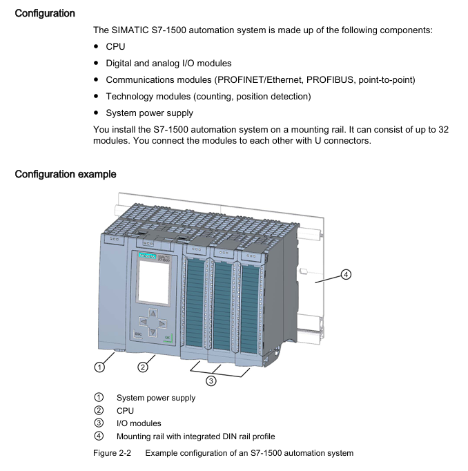
Positioning and advantages: As an upgraded product of S7-300/400, it focuses on high cost-effectiveness and compact design, supports up to 32 modules (slots 0-31), integrates high-speed backplane bus (improves data transmission efficiency), web server (remote monitoring) and Motion Control function (drive control), meets IP20 protection level, and needs to be installed in the control cabinet.
Core components:
Example of Key Parameters for Component Type Function Description
The CPU executes user programs and provides PROFINET/PROFIBUS communication interface model 1518-4PN/DP, supporting 8 communication modules
The system power supply (PS) is powered by the backplane bus, and the diagnostic function integrates PS 25W 24V DC and PS 60W 120/230V AC/DC
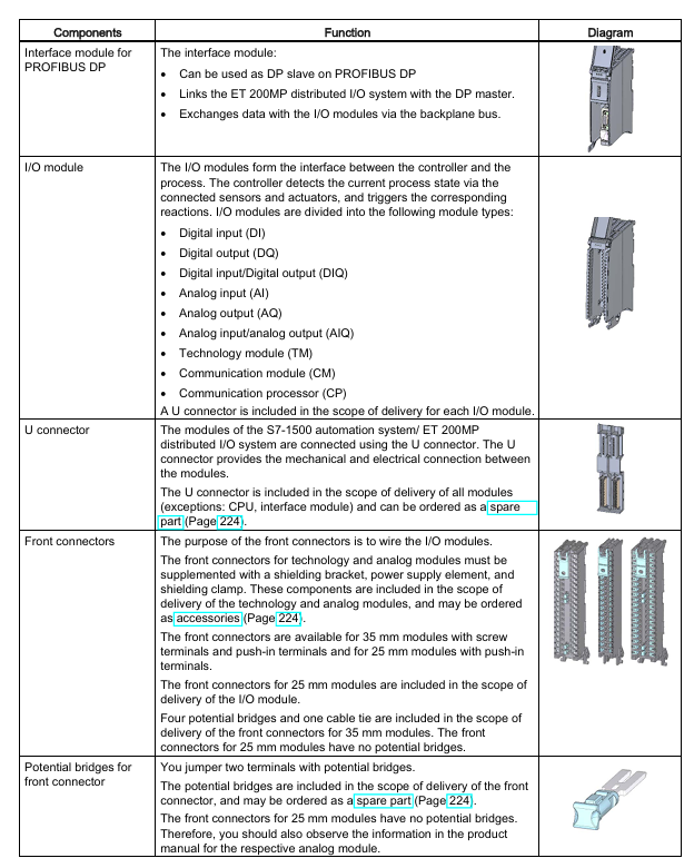
I/O module for digital/analog signal acquisition and output, including technical modules (counting, positioning), digital module DI 32x24VDC HF, analog module AI 8xU/I
Communication module (CM) extends communication interface, supporting point-to-point (RS232/RS485), PROFINET/Ethernet CM 1542-5 (DP master/slave)
2. ET 200MP distributed I/O system
Positioning and advantages: A scalable distributed I/O solution that communicates with the central controller through PROFINET/PROFIBUS, supports high channel density (25mm wide module with 32 channels), adapts to S7-1500 I/O modules, and can be flexibly expanded to 30 I/O modules (PN interface) or 12 I/O modules (DP interface).
Core components:
Example of Key Parameters for Component Type Function Description
The interface module (IM) connects distributed I/O with the central controller, and supports isochronous mode (250 μ s cycle) for PROFINET version (IM 155-5 PN ST/HF) or PROFIBUS version (IM 155-5 DP ST) IM 155-5 PN HF
The I/O module is compatible with S7-1500 and supports digital, analog, and technical modules with the same parameters as S7-1500 I/O module
The system power supply (PS) is powered by the backplane bus and needs to be separately configured with the same S7-1500 system power supply
Application planning and hardware configuration
1. Hardware configuration rules
S7-1500 configuration restrictions:
Module type allows maximum number of slots. Please note
Load power (PM) slot 0 has no limit (only 1 is displayed in STEP 7) and does not occupy the backplane bus. External wiring is required
System power (PS) slots 0, 2-31, 3 for supplementing backplane bus power
CPU slot 1: 1 required component, indispensable
I/O modules 2-31, 30 including digital, analog, and technical modules
Communication module 2-31 4-8 (depending on CPU model) CPU 1511-1PN supports 4, 1518-4PN/DP supports 8
ET 200MP configuration limit:
Interface type allows maximum number of I/O modules in the slot. Remarks
PROFINET (IM 155-5 PN) slot 1 30 (slots 2-31) supports system power expansion (up to 3)
PROFIBUS (IM 155-5 DP) slots 2 12 (slots 3-14) without system power expansion function
2. Power configuration and power balance
Classification of power supply types:
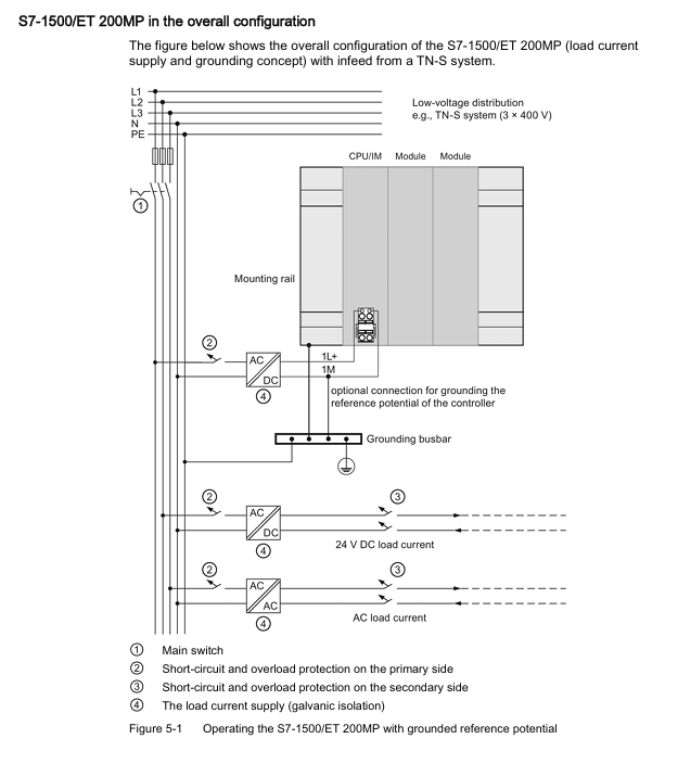
System power supply (PS): only supplies power to the backplane bus (module electronic components, LEDs), needs to be connected to the backplane through a U connector, supports 24/48/60V DC or 120/230V AC input;
Load Power Supply (PM): Provides power to I/O module input/output circuits, sensors/actuators, without backplane bus connection, installed on rails but not occupying slots, recommended Siemens SIMATIC series (PM 70W/190W 120/230V AC).
Power balance calculation: It is necessary to ensure that the backplane bus "supply power ≥ consumption power", and STEP 7 will automatically verify. If the power is insufficient, the system power supply needs to be added. The calculation logic is as follows:
Calculate the backplane power supply of CPU/interface modules (such as 14W provided by CPU 1516-3 PN/DP);
Accumulate the power consumption of each I/O module (such as DI 32x24VDC HF consumption of 1.1W);
If the total consumption exceeds the supply, a system power supply (such as PS 25W to supplement 25W) needs to be added to slot 2-31.
Installation and wiring specifications
1. Installation process and requirements
Guide rail installation: Use TH 35 standard guide rails (length 160/245/482.6/530/830/2000mm), with M6 fixing screws (torque 4Nm). For guide rails ≥ 530mm, fixing screws should be added every 500mm;
Module installation sequence: From left to right, it is "System power supply (optional) → CPU/interface module → I/O module". The modules are mechanically and electrically connected through U connectors, and the last module does not require the installation of U connectors;
Minimum gap: A gap of ≥ 25mm (for heat dissipation and operation space) should be left at the top/bottom of the module. The operating temperature for horizontal installation is 0-60 ℃, and for vertical installation it is 0-40 ℃.
2. Wiring rules
Power wiring:
CPU/Interface Module: Connected to 24V DC (L+, M) through a 4-pole plug, with wire cross-sections of 0.25-2.5mm ² (multiple strands without conduit) and 0.25-1.5mm ² (multiple strands with conduit), and a stripping length of 10-11mm;
System power supply/load power supply: Connected through an encoded power plug, AC input needs to distinguish L1/N, DC input needs to distinguish L+/M, wire stripping length is 7-8mm, torque is 0.5-0.6Nm.
Front connector of I/O module:
Connector type, applicable module width, wiring method, key parameters
Screw terminal 35mm tool fastening supports 2 wires (total cross-section ≤ 1.5mm ²), torque 0.4-0.7Nm
Spring type terminal (push in) 35mm/25mm, tool free hard wire directly inserted, multi strand wire needs to be stripped 8-11mm
The simulation module requires additional installation of shielding brackets and shielding clamps to ensure EMC protection (interference current is grounded through the rail).
Configuration and Debugging Process
1. Software Configuration (STEP 7 TIA Portal)
Basic configuration steps:
Create a project and add S7-1500/ET 200MP devices;
Hardware detection: After connecting to the CPU online, the actual configuration is automatically read through "Hardware detection" to avoid manual input errors;
Address allocation: STEP 7 automatically assigns I/O addresses (digital modules by bit/byte, analog modules by word), supports manual adjustment, can be divided into 32 process image partitions (PIP), PIP 0 is automatically updated, PIP 1-31 can be bound to OB blocks;
Download configuration: The CPU needs to be in STOP mode, and check "Consistent download" to ensure data integrity.
Key configuration functions:
Configuration control: "one main configuration adapts to multiple sub configurations" is realized through control data record (No. 196), which supports module slot adjustment or omission. It is necessary to call WRREC command to transmit data in startup OB;
Block protection: Set know-how protection (password encryption, only displaying interfaces and comments) and copy protection (binding CPU/SIMATIC storage card serial number) for OB/FC/FB/DB.
2. Debugging process
First power on inspection:
Confirm correct wiring (power supply, grounding, I/O circuit);
Insert SIMATIC memory card (required, supports 24MB-2GB, distinguishes program card/firmware update card);
After power on, the CPU performs a self-test (LED flashes all → STOP light turns yellow). If there is a fault, check the diagnostic buffer.
IO testing:
Scan the PROFINET network and test I/O wiring using the PRONETA tool (free of charge);
Monitor/modify variables through STEP 7 "Watch&Force Tables", or directly operate on the CPU display screen (supporting forced peripheral input/output).
Program processing and security protection
1. Fundamentals of Program Processing
Organizational Block (OB): Execute based on event triggers, priority 1-26 (1 lowest, 26 highest), core OB functions are as follows:
OB Number Triggering Event Priority (Default) Function Description
OB 1 loop program 1 main loop executes user program
OB 10-17 timed interrupt 2 triggered at the set time (e.g. every 100ms)
OB 40-47 hardware interrupt 18 triggered by I/O module signal (such as rising edge)
OB 80 time error 22 triggered when cycle time exceeds the limit
OB 121 programming error 7 triggered when there is a syntax error in the program
CPU overload handling: The event queue caches events of the same priority. If the "maximum number of queues" is exceeded, they will be discarded. The time error OB can be triggered through the "event threshold" (such as calling OB 80 when the number of queues is ≥ 1).
2. Safety protection
Access protection: Level 4 permission control, password needs to be configured in CPU properties:
Protection level permission description
Full access to read and write hardware configuration and blocks, no password requirement
Read only access Read only configuration/block, cannot be downloaded, requires password to unlock write permission
HMI access is only available for HMI and diagnostic access, and requires password unlocking for read and write permissions
No access, all access is prohibited. Password unlocking is required
Other protections:
Physical protection: The front cover of the CPU/interface module can be locked (with a diameter of 3mm) or sealed with a seal;
Network protection: Disable unused communication interfaces (such as NTP, PUT/GET), and only allow HTTPS access to the web server.
Maintenance and fault diagnosis
1. Daily maintenance
Module replacement: When replacing the I/O module after power failure, attention should be paid to the coding components (the front connector should be separated from the module when first inserted to ensure that it is only compatible with modules of the same type);
Firmware update: supports 3 methods (online STEP 7, SIMATIC memory card, web server), requires CPU in STOP mode, 2GB card can update CPU 1517/1518 firmware;
Factory reset: By using the mode selector (MRES key), display screen, or executing STEP 7, the IP address and user program will be cleared, leaving only the MAC address.
2. Fault diagnosis
Diagnostic buffer: records CPU/module faults (such as power overload, configuration mismatch), which can be read through STEP 7 or CPU display screen;
Service data reading: In the event of a malfunction, export the DUMP.S7S file through a web server, STEP 7, or SIMATIC storage card for analysis by Siemens technical support;
Testing function:
LED flash test: After triggering, the CPU RUN/STOP/ErrOR/MAINT lights flash to locate the device;
Trace function: records variable changes (such as drive parameters), supports triggering condition settings (such as value exceeding threshold).
Technical Parameters and Appendices
1. Core technical parameters
Environmental parameters:
Parameter Type Range Remarks
Operating temperature 0-60 ℃ (horizontal)/0-40 ℃ (vertical) Display screen automatically shuts down due to overheating
Storage temperature -40-80 ℃ under original packaging conditions
Relative humidity of 10% -95% (no condensation) in accordance with IEC 61131-2 3K3 level
Vibration/shock 5-9Hz (3.5mm amplitude)/250m/s ² (6ms) in accordance with IEC 60068-2-6/27
EMC performance:
Anti interference: electrostatic discharge ± 8kV (air)/± 6kV (contact), surge ± 2kV (power supply)/± 1kV (signal);
Launch: EN 55016 Class A (industrial environment), additional protection is required in residential areas (such as grounding control cabinets).
2. Appendix Resources
Dimensional drawings: including detailed dimensions of guide rails, shielding brackets, and label strips (e.g. 35mm module shielding bracket width 25mm);
Accessories list: Core accessory models (such as front connector 6ES7592-AM00-0XB0, potential bridge 6ES7592-3AA00-0AA0);
- YOKOGAWA
- Reliance
- ADVANCED
- SEW
- ProSoft
- WATLOW
- Kongsberg
- FANUC
- VSD
- DCS
- PLC
- man-machine
- Covid-19
- Energy and Gender
- Energy Access
- Renewable Integration
- Energy Subsidies
- Energy and Water
- Net zero emission
- Energy Security
- Critical Minerals
- A-B
- petroleum
- Mine scale
- Sewage treatment
- cement
- architecture
- Industrial information
- New energy
- Automobile market
- electricity
- Construction site
- HIMA
- ABB
- Rockwell
- Schneider Modicon
- Siemens
- xYCOM
- Yaskawa
- Woodward
- BOSCH Rexroth
- MOOG
- General Electric
- American NI
- Rolls-Royce
- CTI
- Honeywell
- EMERSON
- MAN
- GE
- TRICONEX
- Control Wave
- ALSTOM
- AMAT
- STUDER
- KONGSBERG
- MOTOROLA
- DANAHER MOTION
- Bentley
- Galil
- EATON
- MOLEX
- Triconex
- DEIF
- B&W
- ZYGO
- Aerotech
- DANFOSS
- KOLLMORGEN
- Beijer
- Endress+Hauser
- schneider
- Foxboro
- KB
- REXROTH
- YAMAHA
- Johnson
- Westinghouse
- WAGO
- TOSHIBA
- TEKTRONIX
- BENDER
- BMCM
- SMC
- HITACHI
- HIRSCHMANN
- XP POWER
- Baldor
- Meggitt
- SHINKAWA
- Other Brands
- UniOP
- KUKA
- IBA
- Beckhoff
-
LTI SC52.0040.0012.0000.0 - Servo Drive
-
Lti SC52.0040.0012.0000.0 - Servo Drive
-
Milton Industries LTI Tool By Milton LT1240 - 1/2" Drive Lugnut Remover
-
LTi Drives SO84.200.P030.0000.0-W - Servo Spindle Drive
-
LTI DRIVES LSP08-035-320-30-B0R1PY170 - Servo Motor
-
LTI DRIVES SE84.200.SC00.0001.0-W - Servo Drive
-
Lust CDE34.005.W2.2 - Lti Drives Controller
-
LTi SO84.012.0030.0011.2 - ServoOne Servo Drive
-
LTi Drives SO CM-P.0010.11.00.0 - Servo Drive Controller
-
LTi CDE34.017.W3.0 - Servo Drive
-
LTI Drives CDB32.004, C2.0,SH - Positioning Controller
-
LUST CM-CAN1 - LTi DRIVES Communication Module
-
LTi SO84.012.1030.0000.2 - Servo Drive
-
LTI MOOG CDE54.044 - PITCHMASTER FREQUENCY CONVERTER 181-01019
-
MOOG LTI 181-01019 CDE54.044 - PITCHMASTER FREQUENCY CONVERTER
-
Lust LTi Drives CDE34.010,D2.0 - Servo Drive Controller
-
LTI SO84.032.0003.0101.2 - Servo Drive
-
Seagate 9CC132-302 Harris LTI-CS IRT-34-0021-01 - Hard Drive 160GB
-
LTI SO84.032.0003.0001.2 - Servo Drive
-
LTI SO24.007.0070.0000.1 - SERVO CONTROLLER
-
LTi drive CDA32.003.C3.0.H05-01.PC1 - Servo Drive
-
LTI SO84.016.0030.0000.2 - SERVO CONTROLLER
-
LUST LTI CD A34.008,W1.4, BR - SERVO DRIVE
-
MOOG LTI 181-01019 CDE54.044 - PITCHMASTER FREQUENCY CONVERTER
-
LTI MOOG 181-01019 - PITCH Master Servo Drive CDE54.044
-
LTI SERVO ONE SO84.045.0030.0001.2-W - Drive
-
LUST LTi SO84.032.0040.0000.2 - SERVO ONE DRIVE
-
LTi Drives LSH-074-2-30-3 20/T1,G6.1M - SERVO MOTOR
-
LTI SO84.016.0000.0101.2 - servo drive
-
LTI SA54.0550.0033.0000.0 - Servo Drive
-
LTI SA54.0550.0033.0000.0 - Servo Drive
-
LTI LT 4850 - 3/8" Drive 3-Pc Twist Socket Transmission Drain Plug Removal System
-
LTI Tools LT4400-30 Lock Technology - 3/4" Twist Socket 1/2" Drive Lugnut Remover
-
LTI Tools LT-1400C - 1/2 Drive Wheel Torque Extension Tool
-
LTI Tools LT1250 - 1/2" Drive Dual Sided Socket Lug Nut Remover Tool
-
LTI SO84.032.0003.0101.2 - Servo Drive
-
LTI MOOG 181-01019 - PITCH Master Servo Drive CDE54.044
-
MOOG LTI 181-01019 CDE54.044 - PITCHMASTER FREQUENCY CONVERTER
-
MOOG LTI 181-01019 CDE54.044 - PITCHMASTER FREQUENCY CONVERTER
-
MOOG LTI 181-01019 CDE54.044 - PITCHMASTER FREQUENCY CONVERTER
-
LTI SA54.0550.0033.0000.0 - Servo Drive
-
LTI Tools LT-4800 - 7 Piece Twist Socket 3/8" Drive Oil Drain Plug Removal Set
-
LTI SA54.0550.0033.0000.0 - Servo Drive
-
LTI Drive SO24.007.00300000.0 - Servo Drive
-
LTI TOOLS LTI 1400-I - Drive Wheel Torque Extension
-
LTI Tools LT4400-3 - 3/4" 19mm Twist Socket 1/2" Drive Lugnut
-
LTI TOOLS LTI 1400-BB - Drive Wheel Torque Extension
-
LTI SO84.032.0003.0101.2 - Servo Drive
-
LTI Tools LT-4512 - 3/8" Drive 12mm Twist Socket
-
LTI MOTION Luster SO84.032.0003.0001.2 - Servo Drive
-
LTI Tool By Milton LT1600P - 1" Drive Torx Stick
-
LTI Lust VF1424L,HF,OP2,S56 - Variable Frequency Drive
-
LUST CDA32.004,C1.4,H08,B0 - SERVO DFRIVE CM-CAN1 Module
-
LTI SO84.045.0002.0001.2-W - Drive
-
LTI Lust VF1404M,C9,PT1,BR1 - Inverter Type VF1404M
-
LTI SA54.0550.0033.0000.0 - Servo Drive
-
LTI Tools LT-1400C - 1/2" Drive Wheel Torque Extension
-
Lust LTI DRiVES CDA32.006, C3.0, H09 - Variateur De Fr茅quence Frequency Inverter
-
LTI MOOG CDE54.044 - PITCH master SERVO DRIVE
-
LTI MOOG CDE54.044 - PITCH master SERVO DRIVE
-
LTI SO84.143.0020.0101.2-W - servo drive
-
LTI MOTION SC34.0200.0011.0000.0 - Servo drives
-
LTI SO84.032.0003.0001.2 - Servo Drive
-
LTI DRIVES GmbH MS100 - Assembly Set Mounting Kit
-
LTI SO84.032.0003.0001.2 - Servo Drive
-
LTI SO84.032.0003.0001.2 - Servo Drive
-
LTI MOTION SO84.032.0003.0101.2 - servo drive
-
LTI SO84.032.0003.0101.2 - Servo Drive
-
LTI MOOG CDE54.044 - PITCH master SERVO DRIVE
-
LTI MOTION CDE32.004.C2.4 - Servo drives
-
LTI CDD34.032锛學x.x锛孊R锛孭C1 - Servo Drive
-
Lust LTI DRiVES CDA32.006, C3.0, H09 - Inversor De Frecuencia Frequency Inverter
-
Lust SO84.008.0030.1000.0 - Servo One LTi Drive
-
LTI MOTION SO84.032.0003.0101.2 - Servo drives
-
LUST LTi CDA32.004,C1.4 - SERVO DRIVE
-
LTI MOOG CDE54.044 - PITCH Master SERVO DRIVE
-
LTI KEBA CDB32.004 C2.7, SH - PN: 08673530 Frequency Inverter
-
LTI Tools LT-1400C - 1/2" Drive Wheel Torque Extension
-
LTI LT1400-E - 1/2" Drive Wheel Torque Extension
-
LTI MOOG 181-01019 - PITCH master SERVO DRIVE CDE54.044
-
LTI LSN-097-0510-30-560/T1 - Actuator Motor
-
LTI Tools LT 4800 - 7 Piece 3/8" Drive Twist Socket Oil Drain Plug Removal System
-
LTI DRIVES GmbH MS100 - MONTAGESET Assembly Set Mounting Kit
-
Lti SC52.0040.0012.0000.0 - Servo Drive
-
LTI DRIVES GmbH MS100 - Juego De Montaje Assembly Set Mounting Kit
-
LTi DSM4-14.2-21R83-200 - Drives servomoteur Servo Motor
-
MOOG CDE 54.044.GDA - Pitch Master Industrielle Turbine Lti Drive
-
LTI SO24.004.0030.1000.0 - Servo Drive Controller
-
Lti MOOG CDE54.044 - Pitch Master Servo Drive
-
Lust LTI DRiVES CDA32.006, C3.0, H09 - Inverter
-
LTI MOTION GMBH CDB34.006,W3.0,PC1,H39 - Frequency inverter
-
LTI SO84.032.0003.0001.2 - Servo Drive
-
MOOG CDE 54.044.D - Pitch Master Industrielle Turbine Lti Drive
-
LTI TOOLS LT-1460 - 1/2" DRIVE WHEEL TORQUE EXTENSION KIT 5 PIECE SET
-
Lust Cdb32.003, C2.4 - Lti Drives Servoregulador Frecuencia Servo Controller Inverter
-
Lust LTI DRIVES CDA32.006, C3.0, H09 - Frequency Inverter
-
Lust Lti SO82.004.0030.0000.2 - Servo Drive
-
LTI MOTION SC34.0200.0011.0000.0-SL - Servo drives
-
LTI MOTION SA54.0075.0033.0000.0 - Servo drives
-
LTI MOTION SC32.0075.1011.0000.0 - Servo drives
-
Lust Cdb32.003, C2.4 - Lti Drives Servo Controller Frequency Inverter
-
LTI MOOG CDE54.044 - PITCH master SERVO DRIVE
-
Lust Lti Cde34.006,W2.0,Br - Servo Drive
-
Lust LTi MOTION CDE34.044,W2.4,H13 - Servo Drive
-
Lust LTi Drives Cde32.008, W2.2.br - Positionierregler Posici贸n Mando Positioning Controller
-
LTI MOOG CDE54.044 - PITCH master SERVO DRIVE
-
LUST Antriebstechnik B-DS 125.1 - LTi DRiVES Accessories Drive Component
-
LTi LSMM13-100-4N-001 - servo motor
-
Lti CDA32.004 C1.4, H08, B0 - PN: 3084456 Frequency Inverter
-
LTI MOTION CDE34.006.WXX.PC1 - Servo drives
-
LTI MOTION SO24.007.0030.1000.0 - Servo drives
-
Lust CDD34.005.C2.1 - LTI Drive
-
Lti SC52.0040.0012.0000.0 - Servo Drive
-
LTI Tools LT4400-30 - 1/2" Drive 19mm 3/4" Twist Socket
-
Lust LTi Drives Cde32.008, W2.2.br - Positionierregler Posici贸n Mando Positioning Controller
-
LTI MOOG CDE54.044 - PITCH master SERVO DRIVE
-
LUST Antriebstechnik B-DS 125.1 - LTi DRiVES Accessories Drive Component
-
LTI DRIVES GmbH MS100 - MONTAGESET Assembly Set Mounting Kit
-
Lust LTi SO84.032.0043.0000.2 - Servo one Drive
-
LUST LTi Drives CM-CAN1 - Modulo Di Comunicazione Communication Module
-
LTI drive CDF 30.008.C3.6 - Servo Drive
-
LTI MOOG 181-01019 - PITCH master SERVO DRIVE
-
LTI CDB34.014,W2.4,BR,SH - Servo Driver
-
Lti SC52.0040.0012.0000.0 - Servo Drive
-
LTi Drive CDF30.002 - Power Supply Fuse
-
LTI Tools LT-4621-D - Deep Well Twist Socket 3/8" Drive 1/2"
-
LTI MOOG PITCH master CDE54.044 - SERVO DRIVE Frequency Converter
-
LTI SO84.076.S030.0001.2-W - Servo One Drive

K-JIANG

Add: Jimei North Road, Jimei District, Xiamen, Fujian, China
Tell:+86-15305925923