
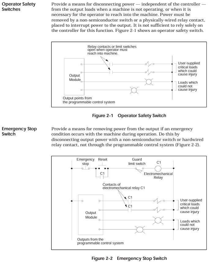
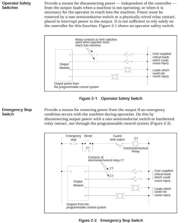
K-WANG


SIEMENS SIMATIC TI545/TI555 Controller
SIEMENS SIMATIC TI545/TI555 Controller
Overview
The SIMATIC TI545/TI555 controller system manual focuses on the hardware installation, system wiring, program storage, startup, and troubleshooting of TI545-1102 and TI555-1101/1102 CPUs. It specifies that the system supports Series 505 local base (4/8/16 slots) and Series 500 remote base (requires PPX: 500-5114A RBC conversion), and hardware installation must follow the power budget (+5V 55W, -5V 3.75W), grounding specifications (grounding resistance ≤ 0.1 Ω), and anti-interference design (shielded twisted pair, noise suppression); The program can be stored in EEPROM/EPROM (128K/256K bytes), and startup requires completing memory configuration (TI545 maximum 192K bytes, TI555-1102 maximum 1920K bytes) and I/O registration; Troubleshooting relies on LED status indication, auxiliary functions (AUX 10/11/12/20/25/29), and RS-485 cable detection (line resistance 52-87 Ω), while providing Series 500 system upgrade solutions to adapt to discrete/analog control scenarios in industrial automation.
Core characteristics of the system
Control capability: Supports discrete/analog control, can execute relay ladder logic (RLL), PID loop, special function program (SFPGM), supports 256 SF modules;
Communication ability:
Local communication: 2 RS-232/422/485 ports (baud rate 300-19200), supporting programming devices/printers/modems;
Remote I/O: 1 RS-485 I/O port, maximum connection to 15 remote bases, distance 3300 feet (1km);
Storage capacity: Supports EEPROM/EPROM non-volatile storage (128K/256K bytes), RAM configurable (TI545 up to 192K bytes, TI555-1102 up to 1920K bytes);
Compatibility: Supports Series 505 local dock and Series 500 remote dock (requires RBC conversion), compatible with old system upgrades.
Hardware Installation Specification
1. Base and module installation
(1) Base type and installation
Key requirements for base model, slot number, installation method
PPX: 505-6504 4 panel installation requires NEMA enclosure with a spacing of ≥ 6 inches (heat dissipation)
PPX: 505-6508 8-panel installation screw hole size as shown in Figure 3-4, torque 2.6-5.22 in lb
PPX: 505-6516 16 16 rack/panel installation compatible with 19 inch rack, depth 7.99 inches
Series 500 6/8/12/14/16 panel installation requires PPX: 500-514A RBC conversion to remote base
(2) CPU installation
Installation location: Series 505 base second slot (adjacent to the power supply);
Battery configuration: 3V rechargeable lithium battery, switch 9 (DIP switch) control enable, backup for 6 months at 0-60 ℃, BATT GOOD light flashes when low battery level;
DIP switch settings:
Switch 1: Port2 mode (left=RS-422, right=RS-485);
Switch 2: Port1 function (left=programming port, right=printer port);
Switch 3-5: Port 1 baud rate (On=1, Off=019200=On/On/On);
Switch 6-8: Port 2 baud rate (same as Port 1);
Switch 9: Battery Enable (Left=On, Right=Off).
(3) Installation of Remote Base Controller (RBC)
Applicable scenarios: Series 505 remote base with PPX: 505-6851A, Series 500 remote base with PPX: 500-5114A;
Installation location: Remote base second slot;
Key settings:
Base number: Thumbwheel set 1-15 (0 is the local base, not available);
Baud rate: PPX: 505-6851A uses DIP switch 2 (Table 3-4), PPX: 500-5114A uses Thumbwheel (Table D-1);
Output hold: When the jumper selects communication interruption, output "hold" or "turn off".
2. Power installation and budget
(1) Power supply model and parameters
Power supply model Input voltage Output power Applicable scenarios
PPX: 505-6660A 110/220V AC (jumper selection)+5V 55W, -5V 3.75W AC power supply scenario
PPX: 505-6663 20-30VDC+5V 55W, -5V 3.75W DC power supply scenario
(2) Power budget calculation
Total power=sum of all modules+5V power+sum of all modules -5V power, must be ≤ 55W (+5V) and 3.75W (-5V);
Typical module power: CPU 4W, RBC 5W, analog module 4-5W, see Appendix B Table B-1 for details.
3. Anti interference and grounding design
Noise suppression:
Noise source: motor, frequency converter, welding machine, with a spacing of ≥ 3 feet;
Suppression measures: Add RC/MOV buffer to inductive load (Figure 2-5/2-6), and use shielded twisted pair cable (12 twisted per foot) for signal;
Grounding specifications:
Grounding resistance ≤ 0.1 Ω, use # 8 copper wire to ground the electrode;
Controller grounding: base → cabinet → grounding electrode, remove the paint surface to ensure conductivity (Figure 2-9/2-10);
Shielded grounding: The input cable is shielded and grounded at the signal source end, and the output cable is shielded and grounded at the base end (single ended grounding).

System cabling and connections
1. Cable selection and wiring
(1) Key cable types
Recommended cable usage, key parameters, maximum length
RS-485 backbone Belden 9860 16AWG, impedance 124 Ω, capacitance 35.8pf/m 3300 feet (1006m)
RS-485 branch line Belden 9271 25AWG, impedance 124 Ω, capacitance 40pf/m 33 feet (10m)
RS-485 backup wire Belden 9182 22AWG, impedance 150 Ω, capacitance 28.9pf/m 2200 feet (670m)
Power connection wire 14AWG copper wire, temperature resistance ≥ 75 ℃, rated voltage ≥ 300V, short distance (≤ 10 meters)
(2) RS-485 wiring specification
Topology structure:
Main line: star (T-shaped) or bus type, avoiding multiple branches (Figure 4-8/4-9);
Terminal resistance: Add 120 Ω (9860/9271) or 150 Ω (9182) to both ends of the base, and do not add to the middle base;
Length limit:
2-5 terminal blocks: 9860 up to 3300 feet, 9182 up to 2200 feet;
16 terminal blocks: 9860 maximum 2200 feet, 9182 maximum 1467 feet (Table 4-2);
Wiring method: Underfloor/ceiling/surface trunking, avoid parallel connection with power cables (Figure 4-4/4-5).
2. Peripheral connection
Programming equipment: connected via Port1 (RS-232), distance ≤ 50 feet, using a 9-pin D-type connector (Figure 3-12);
Printer: Set Port1 as the printer port (switch 2 on the right), supporting XON/XOFF or READY/BUSY handshakes (Figure 4-13/4-14);
Modems: Port 1 connection, supports dedicated line (DCE interface, V.32 error correction) or dial-up (TIDIAL software required), unlimited distance (Figure 4-12).
Program Storage and System Startup
1. Program storage medium
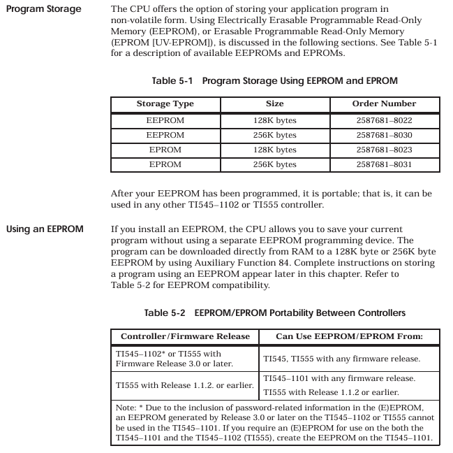
Storage type, capacity, order number, key characteristics
EEPROM 128K bytes 2587681-8022 electrically erasable, supports RAM<->EEPROM replication, portable (Release 3.0+CPU universal)
EEPROM 256K bytes 2587681-8030 on the same left, with larger storage capacity
EPROM 128K byte 2587681-8023 UV erase, EEPROM copy required, not directly programmable
EPROM 256K bytes 2587681-8031 on the same left, with larger storage capacity
(2) EEPROM operation (AUX 84)
Copy RAM → EEPROM: The EEPROM needs to be erased first to ensure that the user program is ≤ 126K/254K bytes;
Copy EEPROM → RAM: If there is a program in EEPROM and the battery is damaged during power on, it will be automatically loaded into RAM;
Erase EEPROM: Select "Erase" for AUX 84, the program cannot be restored after erasing.
2. System startup process
(1) Initial startup steps
Initialize CPU:
Turn off the battery (switch 9 on the right), disconnect the power, and ensure that there is no EEPROM/EPROM;
Power on, CPU clears memory and enters Program mode;
Turn on the battery (left of switch 9), the BATT GOOD light will turn on (fully charged after 36 hours);
Configuration and Download:
Connect programming device (TISOFT 5.0+), configure memory (Table 6-1/6-2) and I/O base;
Download user program, JOG test actuator (motor/solenoid valve);
Switch to Run: Set the CPU to RUN mode and check that the CPU GOOD and RUN lights are on.
(2) Memory configuration (example)
CPU model, memory type, minimum capacity, maximum capacity, block size
TI545-1102 L (trapezoidal) 1K bytes 59K bytes 1K bytes (occupying 3K of system memory)
TI545-1102 V (variable) 1K bytes 177K bytes 1K bytes
TI555-1102 L (trapezoidal) 1K bytes 635K bytes 1K bytes (occupying 3K of system memory)
TI555-1102 V (variable) 1K bytes 1905K bytes 1K bytes
Troubleshooting and System Upgrade
1. Fault diagnosis tool
(1) LED status indication
LED name status meaning
CPU GOOD lights up. CPU has no fatal errors and is running normally
CPU GOOD extinguishes fatal errors (ROM failure, watchdog timeout, etc.)
RUN is on, CPU is in RUN mode
RUN flashing analog operation, discrete programming mode
BATT GOOD lights up, the battery is normal and enabled
BATT GOOD flashing battery charging or low battery level
BATT GOOD battery disabled or damaged
(2) Auxiliary functions (AUX)
Auxiliary Function Usage Key Operations
When the AUX 10 is powered on and the battery is restarted, it maintains V memory and clears memory when it is turned off
AUX 11 partially restarts to clear discrete I/O and maintain L/V/K/S memory
AUX 12 fully restarts and clears all I/O and timers/counters, downloads preset values
AUX 20 runs diagnostic tests on RAM/ROM/hardware, displaying the location of the fault
AUX 25 displays faulty I/O and lists unconfigured or faulty I/O modules
AUX 29 displays the diagnostic unit's scan time, mode, and battery status (Figure 7-1)
2. Common fault handling
Possible causes and solutions for the fault phenomenon
CPU GOOD ROM diagnostic failure, return to factory for repair
CPU GOOD extinguishes watchdog timeout check program scanning time, AUX 11 restarts
Communication failure RS-485 cable fault. Measure the inter line resistance (52-87 Ω) and check the terminal resistance
The battery light is flashing. If the battery is low after charging for 24 hours and still flashes, replace it
I/O unresponsive base unregistered AUX 25 check, reconfigure I/O
3. Series 500 system upgrade
(1) TI520/530 series upgrade
Hardware modification:
Remove the original controller/distributed base controller (DBC);
16/8 slot base with PPX: 500-5840 adapter, equipped with 24V power supply (PPX: 500-2151A);
Install PPX: 500-5114A RBC, with base numbers 1-15;
Wiring renovation:
RS-485 cable (Belden 9860) with a maximum backbone length of 3300 feet;
Add a 120 Ω resistor to the terminal block (base at both ends);
Software configuration:
Reconfigure I/O (base numbers 1-15) and download the program.
(2) TI560/565 series upgrade
RS-485 type: Remove the original CPU directly, connect the RS-485 cable to TI545/TI555 I/O ports, and change the base number to 1-15;
RF type: Add PPX: 505-6860 RF → RS-485 converter, then connect to TI545/TI555, change base number 1-15.
Appendix Key Information
1. Environmental Parameters (Appendix A)
Parameter indicators
Working temperature 0-60 ℃ (32-140 ℉)
Storage temperature -40-70 ℃ (-40-158 ℉)
Relative humidity 5% -95% (non condensing)
Vibration sine: 10-57Hz 0.15mm peak to peak value; Random: 57-150Hz 1.0g
Electrostatic discharge IEC 801-2 Level 4 (15kV)
Isolation Voltage Field - Controller 1500Vrms
2. Recommended spare parts (Appendix 7.9)
Base: PPX: 505-6504/6508/6516;
Power supply: PPX: 505-6660A/6663;
Fuse: 3A slow melting (6660A), 8A fast melting (6663);
Storage media: EEPROM 128K/256K, EPROM 128K/256K;
Cable: RS-232 programming cable (2601094-8001).
- YOKOGAWA
- Reliance
- ADVANCED
- SEW
- ProSoft
- WATLOW
- Kongsberg
- FANUC
- VSD
- DCS
- PLC
- man-machine
- Covid-19
- Energy and Gender
- Energy Access
- Renewable Integration
- Energy Subsidies
- Energy and Water
- Net zero emission
- Energy Security
- Critical Minerals
- A-B
- petroleum
- Mine scale
- Sewage treatment
- cement
- architecture
- Industrial information
- New energy
- Automobile market
- electricity
- Construction site
- HIMA
- ABB
- Rockwell
- Schneider Modicon
- Siemens
- xYCOM
- Yaskawa
- Woodward
- BOSCH Rexroth
- MOOG
- General Electric
- American NI
- Rolls-Royce
- CTI
- Honeywell
- EMERSON
- MAN
- GE
- TRICONEX
- Control Wave
- ALSTOM
- AMAT
- STUDER
- KONGSBERG
- MOTOROLA
- DANAHER MOTION
- Bentley
- Galil
- EATON
- MOLEX
- Triconex
- DEIF
- B&W
- ZYGO
- Aerotech
- DANFOSS
- KOLLMORGEN
- Beijer
- Endress+Hauser
- schneider
- Foxboro
- KB
- REXROTH
- YAMAHA
- Johnson
- Westinghouse
- WAGO
- TOSHIBA
- TEKTRONIX
- BENDER
- BMCM
- SMC
- HITACHI
- HIRSCHMANN
- XP POWER
- Baldor
- Meggitt
- SHINKAWA
- Other Brands
- UniOP
- KUKA
- IBA
- Beckhoff
-
Basler Electric DECS-250-CN1SN1N Automatic Voltage Regulator for Generator Excitation Control
-
ADLINK CPCI-6860A - 51-31310-OB10 industrial motherboard CompactPCI SBC
-
ADLINK AmITX-SL-G-H110 - 51-7A104-0A30 Mini-ITX Industrial Motherboard
-
ADLINK PXI-2005-003 - CPCI Industrial PC Data Acquisition Card Multi-Function DAQ
-
ADLINK DININ-814M - 51-14032-0A3D SCSI-100P cable connection Interface Terminal Board
-
ADLINK CPCI-3920NA/C2D15/M1G - 3U CompactPCI Intel Core 2 Duo Single Board Computer
-
ADLINK PCIE-8560 - 51-18014-0A20 Communication Card High Speed DAQ
-
ADLINK PCI-C154+ - Motion Control Card 4-axis Motion Controller Board
-
ADLINK PCI-RTV24 - image capture card Analog Video Frame Grabber
-
ADLINK NuPRO-842LV/P - 51-41360-0B30 Industrial Motherboard CPU Board
-
ADLINK cBP-3208/3208R - CPCI Board 3U 8-Slot CompactPCI Backplane
-
ADLINK PCI-8164 - 4-Axis Motion Controller PCI Card 51-12406-0A40
-
ADLINK PCIe-GIE64+ - 4-CH GigE Vision PoE+ Frame Grabber Video Capture Card
-
ADLINK CPCI-6860 / 6860A - CompactPCI Dual Xeon Single Board Computer
-
ADLINK IEC-915GV - REV 1.1 Industrial motherboard CPU Board
-
ADLINK ND-6520 - Technology RS-232 to RS-422RS-485 Converter NuDAM Module
-
ADLINK RTV-24 / PCI-MP4S - 51-12519-1C30 4-Channel Real Time Video Capture Board
-
ADLINK cPCI-6910 / cPCI-6910AM/M1G - cPCI-6910AM/DXL16/M1G/S80G(G)-3120 BOARD CompactPCI SBC
-
ADLINK NUPRO-A40H - Linghua 51-41807-1A30 Industrial Control Computer Motherboard
-
ADLINK USB-3488A - USB to GPIB INTERFACE USB-3488A(G) Controller Module
-
ADLINK PCI-8134A - motion control card 4-Axis Controller Card
-
ADLINK PCI-7432 - Board 32-Channel input / 32-output Isolated Digital I/O PCI Card
-
ADLINK PCI-8134A - 51-12421-0A10 motion controller card tested
-
ADLINK LPCIe-7230 - 32 CH Isolated Input/output Card 2 Interrupts Low Profile PCIe
-
ADLINK NuPRO-E340 - industrial computer motherboard 51-47807-0A30 PICMG 1.3 SHB
-
ADLINK PCI-7434 - High-speed Digital Acquisition Card 64-CH Isolated DO Card
-
ADLINK NuPRO-E330 - 51-41805-0A20 Indsutrial Board SHB Single Board Computer
-
ADLINK PCI-7248 - OPTO-22 48 CHANNEL DIO DIGITAL TTL/DTL I/O 51-12006-0A40 GP
-
ADLINK PCI-8134 - Motion control card 4-Axis Controller Card
-
ADLINK AMP-208C - Movimiento Control Tarjeta 51-12420-1A20 W/Expansión & Breakout
-
ADLINK PCI-8164 - 51-12406-0A40 PCB Board 4-Axis Motion Controller Card
-
ADLINK DIN-68Y-SGII / DIN-68M-J3A - Terminal Board Connector Interface Block
-
ADLINK PCIe-7432 - Technology 51-18402-0A10 PCIe Card With High Input Range
-
ADLINK PCI-8144 / PCI-8144N - Motion control card 4-Axis Stepper Controller Card
-
ADLINK HSL-HUB3/REPEATER - HIGH SPEED LINK EXTENSION MODULES Distributed Hub Module
-
ADLINK ND-6017 - Data Logging + Acquisition 8CH A/D input Mod NuDAM Module
-
ADLINK LPCIe-7250 - data acquisition card Low Profile 8-CH Relay Output Card
-
ADLINK PCI-7432 - I/O card 64-CH Isolated Digital Input Output PCI Card
-
ADLINK IMB-M43H - industrial control computer motherboard Q87 Chip Micro-ATX
-
ADLINK MP-C154 - Motion control Card 4-Axis Motion Controller Board
-
ADLINK PCI-RTV24 - image capture card Video Frame Grabber Card
-
ADLINK PCI-7250 - 8-CH Relay Output & 8-CH Isolated DI Card
-
ADLINK PCI-6308V - 8-CH 12-Bit Isolated Analog Output PCI Card PCB-I-E-1148=6EX2
-
ADLINK PCI-7248 - capture card 48-CH Opto-22 Compatible DIO Card
-
ADLINK HSL-AI16A02-M-VV - Analog Input Output Distributed Module
-
ADLINK NuPRO-A301 - Rev:1.4 NUPRO-A301 PICMG Full-Size Single Board Computer
-
ADLINK PCI-6208V-GL - 8-CH Voltage Analog Output PCI Card
-
ADLINK PCI-8134A - 51-12421-0A10 4-Axis Motion Controller Card
-
ADLINK MNET-S23 - TECHNOLOGY MNET S23 - SERVO DRIVER CONTROL MODULE
-
ADLINK M-342 - ATX I3 I5 I7 Q67 Industrial Motherboard
-
ADLINK NUPRO-780 - Industrial Motherboard CPU Board PICMG SBC
-
ADLINK MP-C154 / MP-C152 - 4-Axis Motion Control Card Pulse-Train Controller
-
ADLINK NuPRO-935A/LV10B0 - Motherboard 51-41802-0A10 GP w/RAM Industrial Control Board
-
ADLINK MP-C154 - Motion control card 4-Axis Motion Controller Mainboard
-
ADLINK PCI-7250 - PCI Acquisition Card 8-CH Relay Output Isolated DI Card
-
ADLINK ACL-7124 - Technology Inc.24 DIO Card Digital Input Output Card
-
ADLINK PCI-8554 A2 - Timer/Counter Data Acquisition Card
-
ADLINK DIN-825-GP4 - Terminal Block Interface Board Breakout Module
-
ADLINK NuPR0-761 - REV:1.1 Industrial motherboard Full-Size PICMG SBC
-
ADLINK MXE-1401/M8G (G) - Matrix Fanless Embedded Computer Industrial PC
-
ADLINK HSL-DI16DO16-UD-NN - Digital 16 Channel I/O Mod Distributed I/O Module
-
ADLINK ND6520 - NUDAM INTELLIGENT DA&C MODULE RS232-RS-422/RS485 CONVERTOR
-
ADLINK NUPRO-761 - REV:1.1 Industrial Motherboard CPU Board
-
ADLINK AMP-208C - Motion Control Card 51-12420-1A20 DSP-based 8-axis
-
ADLINK NuPRO-A301REV 1.4 - with packaging industrial computer motherboard PICMG SBC
-
ADLINK PCM-9112+ - 51-12300-0A2 industrial motherboard Multi-Function DAQ PC/104 Module
-
ADLINK PCM-7250+ - 8-CH Relay Outputs & 8-CH Isolated DI Module PC/104
-
ADLINK PCI-RTV24 - Image capture card Analog Video Frame Grabber
-
ADLINK PCI-8134 - Motion Controller PCI Card 4-Axis Controller Board
-
ADLINK PCI-7432 - Isolated Digital I/O PCI Card
-
ADLINK PCI-8554 A2 - acquisition card Timer/Counter Card
-
ADLINK PCI-8132 - Rev.A2 2-Axis Servo & Stepper Motion Controller Card
-
ADLINK PCI-8132 - Data Acquisition card 2-Axis Motion Controller Card
-
ADLINK EBP-13E4 - 51-46703-0A30 Industrial Backplane Board Passive Backplane
-
ADLINK PCI-800L - Electronic Card Interface Controller Card
-
ADLINK PCIe-GIE72 - 51-18531-0A10 PCB Board GigE Vision Frame Grabber
-
ADLINK DAQ-2010(G)-OOBO - Simultaneous-Sampling Multi-Function DAQ Card
-
ADLINK PCI-9112 - REV.B1 Multifunction DAQ Card Data Acquisition Card
-
ADLINK PCI-7230 - 51-12003-DA60 32-CH Isolated Digital I/O Card
-
ADLINK PCI-7432 - Data Acquisition Card Isolated Digital I/O PCI Card
-
ADLINK ETX-AT-N270-18/LXE - 51-71111-0A20 ETX CPU Module Motherboard
-
ADLINK HSL-DI32-UD-N - DIGITAL INPUT 32 POINTS MODULE Distributed I/O
-
ADLINK AMP-204C - Motion Control card DSP-Based 4-Axis Advanced Controller
-
ADLINK MNET-4XMOG-0050 - Four-axis Motion Controller Distributed Motion Module
-
ADLINK AMP-204C - Motion control card DSP-Based 4-Axis Pulse-Train Controller
-
ADLINK PCI-7442 - Switch card 64-Channel Datalogging & Acquisition Card
-
ADLINK M-302 - Industrial control motherboard ATX PC Board
-
ADLINK NUPRO-852 / NUPRO-852LV - Industrial motherboard Single Board Computer
-
ADLINK PCI-8134 - REV.B1. 4-Axis Motion Controller Card
-
ADLINK PCI-GIE62 + - 51-18502-0A20 2-CH GigE Vision Frame Grabber PoE Card
-
ADLINK PCI-MPG24 - 51-12523-0B20 MPEG4 Card Video Compression Hardware
-
ADLINK HSL-TB32-M-DIN - 32-CH I/O TERMINAL W/ HSL-AI16AO2-M-VV MODULE
-
ADLINK PCI-M114-GL - PCB Ver 2.1 Motion Controller Axis Card
-
ADLINK IMB-M40H - SYM76996H61 motherboard Industrial Computer Mainboard
-
ADLINK NUPRO-A40H - 51-41807-1A20 industrial control motherboard H61 Chip
-
ADLINK PCI-M114-GL - Axis Card Data Acquisition Card PCB VER2.2 Motion Controller
-
ADLINK PCI-8134 - Motion Controller PCI Card 4-Axis Controller Board
-
ADLINK PCI-8102 - Motion control card 2-Axis Servo & Stepper Controller
-
ADLINK NuPRO-841REV:3.0 - motherboard Industrial Control PC Board
-
ADLINK HSL-TB32-U-DIN REV A1 - Breakout Terminal Board Field I/O Module
-
ADLINK AMP-204C - Motion Control card DSP-Based 4-Axis Pulse-Train Controller
-
ADLINK NUPRO-A40H - 51-41807-1A20 industrial control motherboard H61 PC Board
-
ADLINK PCI-6308A / PCI-6308V - 51-12202-0A50 Isolated Analog Output Card
-
ADLINK AMP-204C - DSP-Based 4-Axis Advanced Pulse-Train Motion Controller
-
ADLINK PCI-7434 - Technology 64-Channel Isolated Digital I/O PCI Cards
-
ADLINK CPCI-6840 / CPCI-6840V / PM16/M1G-12G0 - CompactPCI Single Board Computer CPU Module
-
ADLINK PCIE-GIE74 - Motherboard Video Capture Card 51-18531-0A10 Frame Grabber
-
ADLINK NuPRO-E330 - industrial computer equipment motherboard Control Mainboard
-
ADLINK AMP-208C / 51-12420-1A20 - Motion Control Card W/ Expansion & Breakout Board
-
ADLINK HPCI-14S12U - industrial computer baseboard Passive Backplane 14 Slots
-
ADLINK PCI-8164 - 4-Axis Motion Controller PCI Card W/ 1x Cable, 1x Breakout Box
-
ADLINK PCIe-RTV24 - 51-18016-0A20 Image Acquisition Video Capture Card
-
ADLINK M-342 - 5 PCI ATX Motherboard Industrial PC Mainboard
-
ADLINK PCI-FIW64 - 4/2 Channel IEEE1394B Image Capture Card FireWire Frame Grabber
-
ADLINK PCI-7432 - digital IO card 64-CH Isolated Digital Input Output Card
-
ADLINK 51-12001-0C20 - Circuit Board PCI-7200 Data Acquisition Controller Card
-
ADLINK PXI-3920 - PXI 3U cPCI Industrial Controller Embedded System CPU Board
-
ADLINK NuPRO-841REV:2.0 - motherboard Industrial Control PC Board
-
ADLINK NuPro-E330 - 51-41805-0A20 PCB Industrial Control Computer Motherboard
-
ADLINK PCI-RTV24 - Image capture card Analog Video Frame Grabber
-
ADLINK PCI-7442 - Switch card 64-Channel Datalogging & Acquisition Card
-
ADLINK HPX-13S4 - device baseboard Passive Backplane Riser Card
-
ADLINK PCI-9112 REV A.1 - Multi Function DA&C Board Data Acquisition Card
-
ADLINK PCI-7248 - 51-12006-0A40 Card Control 48-CH Digital I/O Module
-
ADLINK CPCI-6860 / 6860A - motherboard CompactPCI Dual Xeon Single Board Computer
-
ADLINK DPAC-3020-11(G) - Embedded PC Automation Controller Machine Control Board
-
ADLINK NuPRO-841 REV:1.0 - industrial control motherboard CPU Board
-
ADLINK MNET-4XMOG-0050 - Four-axis Motion Controller MNET Motion Control Card

K-JIANG

Add: Jimei North Road, Jimei District, Xiamen, Fujian, China
Tell:+86-15305925923