
K-WANG


SIEMIENS SIMATIC 505 Analog I/O Module
SIEMIENS SIMATIC 505 Analog I/O Module
The complete user guide for SIMATIC 505 series analog I/O modules focuses on four single width modules (input module PPX: 505-6108A/6108B, output module PPX: 505-62088A/6208B), covering the entire process of module technology principles, installation and wiring, calibration and maintenance, and troubleshooting. All modules are compatible with the Series 505 controller, and the input module supports 8-channel ± 5V/± 10V voltage or 0-20mA current signal acquisition (12 bit resolution for version A and 13 bit resolution for version B). The output module synchronously provides 8-channel 0-10V voltage and 0-20mA current signals (12 bit resolution); Installation must follow shielded twisted pair wiring and terminal block wiring specifications. The input module does not require an external power supply, while the output module requires a 20-28VDC user power supply; Calibration needs to be carried out every 6-12 months to ensure measurement and control accuracy in industrial scenarios. At the same time, solutions such as LED status indication and fuse replacement are used to ensure stable operation of equipment, suitable for industrial analog signal processing scenarios such as pressure, temperature, and flow.
Overview of Core Framework and Modules
2.1 Basic Information
Applicable module analog input: PPX: 505-6108A, PPX: 505-6108B; Analog output: PPX: 505-6208A, PPX: 505-6208B
The core positioning is aimed at industrial automation engineers, providing a full process operation guide for module selection, installation, configuration, and maintenance
Certified compliance with UL (Industrial Control Equipment), CSA (Process Control Equipment), ATEX Class I Div.2 (Hazardous Areas), CE (Low Voltage/EMC Directive) and other standards
The supporting documents should be used in conjunction with the SIMATIC 505 System Manual, SIMATIC 500/505 TISOFT Release 6.3 User Manual, and other related documents
2.2 Module Core Positioning and Advantages
Design features: Single width structure, can directly replace dual width analog modules (without modifying the original wiring), saving controller slot space;
Function positioning: As a bridge between the Series 505 controller and industrial field equipment, the input module collects analog signals from sensors (such as temperature transmitters and pressure sensors) and converts them into digital signals. The output module converts the controller's digital signals into analog signals to drive actuators (such as regulating valves and frequency converters);
Core advantages: Supports multiple signal types, strong anti-interference ability (1500Vrms isolation), easy installation and maintenance, suitable for harsh industrial environments (0-60 ℃ working temperature, 5% -95% non condensing humidity).
Module technology principles and core parameters
3.1 Analog Input Module (PPX: 505-6108A/6108B)
3.1.1 Working principle
The module adopts analog-to-digital conversion (ADC) technology to convert continuously changing voltage/current signals into discrete digital quantities:
PPX: 505-6108A: Adopting dual slope integral conversion method, strong anti-interference ability, suitable for low-speed stable signal acquisition;
PPX: 505-6108B: Adopting the successive approximation conversion method, the conversion speed is faster and the resolution is higher, suitable for high-precision dynamic signal acquisition.
Both convert current signals into voltage signals through internal 250 Ω± 0.1% precision resistors, and then perform ADC conversion.
3.1.2 Key Technical Parameters
Parameter category PPX: 505-6108A PPX: 505-6108B
Number of channels: 8 channels, single ended input: 8 channels, single ended input:
Signal range voltage: ± 5V (default), ± 10V (jumper selection); Current: 0-20mA Same as left
Resolution of 12 bits+sign bit (± 5V range: 1.25mV/step; 0-20mA range: 5 μ A/step) 13 bits+sign bit (± 5V range: 0.625mV/step; 0-20mA range: 2.5 μ A/step
Conversion accuracy (25 ℃) Voltage: ± 0.5% of full scale; Current: ± 0.7% full-scale voltage: ± 0.25% full-scale; Current: ± 0.35% of full scale
Temperature coefficient voltage: 58ppm/℃; Current: 83ppm/℃ Voltage: 50ppm/℃; Current: 80ppm/℃
The maximum conversion time is 330ms (input system delay); Maximum update time 250ms (full channel), maximum sampling repetition time 25ms
Input protection overvoltage: ± 30VDC (clamp diode); Overcurrent: 30mA (optical isolation) same as left
Power requirement: Base only power supply (from controller): maximum 4W, typical 2.5W. Base only power supply: maximum 4W, typical 1.1W
3.1.3 Digital Format and Signal Conversion
The controller only receives 16 bit digital signals, and the module encapsulates the ADC conversion results into 16 bit words:
PPX: 505-6108A: bits 1-12 are valid data, bit 13 is the sign bit (1=negative, 0=positive), bit 14 is the over range bit (1=over range), bits 15-16 are invalid bits (fixed 0);
PPX: 505-6108B: bits 1-13 are valid data, bit 14 is the sign bit, bit 15 is the overrange bit, and bit 16 is the invalid bit (fixed 0);
Over range determination: When the input voltage exceeds ± 5.00125V (± 5V range) or ± 10.0025V (± 10V range), the over range position 1 and the digital quantity exceed ± 32000;
Conversion formula:
Voltage input (± 10V range): Digital quantity (WX)=(input voltage/10V) × 32000;
Current input (0-20mA range): Digital quantity (WX)=(input current/20mA) × 32000.
3.2 Analog Output Module (PPX: 505-6208A/6208B)
3.2.1 Working principle
The module receives a 16 bit digital signal from the controller and converts it into a continuous analog signal through digital to analog conversion (DAC) technology. The voltage and current outputs are synchronized (the same channel can output two types of signals simultaneously without switching):
The current output is designed as a source type, and in the event of a short circuit, the current will bypass the on-site equipment. It is necessary to avoid short circuits in the output circuit;
If the digital sign bit (bit 1) is 1 (negative value), the module does not update the output and maintains the previous positive value output.
3.2.2 Key Technical Parameters
Parameter category PPX: 505-6208A PPX: 505-6208B
Number of channels: 8 channels, single ended output: 8 channels, single ended output:
Signal range voltage: 0-10VDC; Current: 0-20mA (source type) same as left
Resolution 12 bits (voltage: 2.5mV/step; Current: 5 μ A/step) Same as left
Conversion accuracy (25 ℃) Voltage: ± 0.5% of full scale; Current: ± 0.5% full range same as left
Full temperature range precision voltage: ± 1.45% of full range; Current: ± 1.83% full range same as left
Temperature coefficient voltage: 136ppm/℃; Current: 204ppm/℃ Voltage: 50ppm/℃; Current: 100ppm/℃
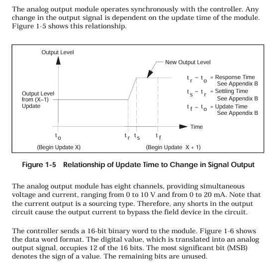
Response characteristic response time: 27ms (minimum) -54ms (maximum); Stability time: Voltage 0.2ms, Current 2.0ms Response time: Maximum 10ms Stability time: Same as left
Load requirement voltage: ≥ 5000 Ω, maximum capacitance 0.01 μ F; Current: 10-600 Ω (over 600 Ω requires 10V power supply, maximum 1000 Ω) Same as left
Power demand base power supply: maximum 2W (typical 1.0W); User Power Supply: 20-28VDC, 0.5A (Ripple ≤± 0.4VDC, UL Class 2) Same as Left
3.2.3 Digital Format and Signal Conversion
The controller outputs a 16 bit digital quantity: bits 1-12 are valid data, bits 13-16 are invalid bits (fixed to 0);
Conversion formula:
Voltage output: Digital quantity (WY)=(target voltage/10V) × 32000;
Current output: Digital quantity (WY)=(target current/20mA) × 32000.
Installation and wiring specifications
4.1 Wiring Core Requirements
4.1.1 Cable selection and protection
Cable specifications: 14-24 AWG (0.18-1.5mm ²) shielded twisted pair, supporting stranded (multi strand) or solid (single strand) wires;
Temperature and voltage resistance: The wire has a temperature resistance of ≥ 75 ℃ and a rated voltage of ≥ 300V, meeting the insulation requirements of industrial environments;
Anti interference measures:
Separate the wiring of signal cables and power cables (such as motor power lines) to avoid parallel laying, and form a 90 ° angle when crossing;
Avoid laying cables on vibrating surfaces, do not bend them into sharp angles, and use cable trays for standardized routing;
Shielding layer grounding: The shielding layer of the input cable is grounded at the signal source end, and the shielding layer of the output cable is grounded at the controller base end. It is strictly prohibited to ground both ends at the same time (to prevent noise caused by ground circulation).
4.1.2 Output module circuit calculation
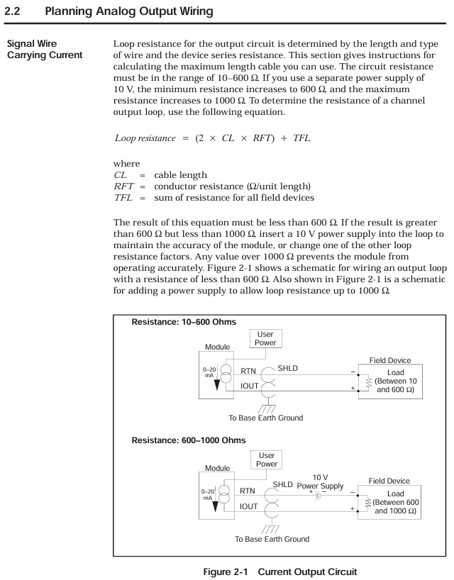
Current circuit resistance: circuit cable equipment (L is the cable length, cable is the unit length resistance, equipment is the on-site equipment resistance); When the circuit is between 10-600 Ω, connect it directly; When the circuit is between 600-1000 Ω, a 10V DC power supply needs to be connected in series in the circuit; When the circuit is greater than 1000 Ω, it is necessary to replace the thick wire diameter cable or shorten the wiring distance, otherwise the output accuracy will decrease.
Fixed error of voltage circuit: The error equipment cables must ensure that the error is within the allowable range.
4.2 Terminal block wiring
4.2.1 Terminal block types and wiring steps
Terminal block model:
Standard configuration: PPX: 2587705-8006;
Optional: PPX: 2587705-8002 (wiring method consistent with standard, can replace old terminal blocks of double width modules);
Wiring steps:
Strip wire 0.25 inches (1.0cm), optional installation of fork/ring terminal blocks (Amp 321462/327891, compatible with # 4 studs);
Connect the wires according to the pin diagram (Figure 2-4), first connect the D terminal, then connect the C, B, and A terminals in sequence, and tighten the screws to ensure good contact;
After the wiring is completed, check the terminal definition to avoid misconnection (such as the "Return" terminal of the input module cannot be suspended, and the "24V common" output module needs to be reliably grounded).
4.2.2 Input module wiring differences
Key points to note for input type wiring method
Voltage input (± 5V/± 10V) signal+connected to voltage input terminal (such as channel 1 connected to A2 "V1 in"), signal - connected to return terminal (A3 "Return 1") does not need to be short circuited, ensuring that the internal resistance of the signal source is ≤ 1k Ω to avoid signal attenuation
Current input (0-20mA): First, short-circuit the current input terminal (A1 "I1 in") to the voltage input terminal (A2 "V1 in"). Connect the signal+to A1 and the signal - to A3. The short circuit should be directly connected with a wire and should not pass through high resistance components to ensure that the current flows through the internal 250 Ω resistor
4.2.3 Typical wiring scenarios
2-wire transmitter wiring (input module): transmitter+connected to input module current input terminal, transmitter - connected to return terminal, module provides power to transmitter through internal circuit;
4-wire transmitter wiring (input module): The transmitter is independently powered, with signal+connected to the current input terminal and signal - connected to the return terminal;
Output module wiring (4-channel example): Each channel simultaneously outputs voltage (such as A2 "V1 out") and current (A1 "I1 out"), which are connected to the corresponding actuators. The common terminal (Return) is grounded uniformly.
4.3 Module Installation and I/O Configuration
4.3.1 Module installation steps
Power off operation: Before installation, turn off the controller and all external power sources to avoid electric shock or component damage;
Slot selection: Insert the module into the idle single width I/O slot of the Series 505 controller, avoiding proximity to high-energy switch modules or EMI sources (such as frequency converters);
Fixed module: Tighten the module panel with screws and control the torque at 2.6-4.12 in lb (0.3-0.6N · m) to avoid damaging the module or base due to over tightening;
Static protection: Do not touch the module circuit board during installation, and wear an anti-static wristband if necessary.
4.3.2 I/O Configuration Process
Configuration tool: Use SIMATIC 500/505 TISOFT Release 6.3 software to connect the controller through programming devices;
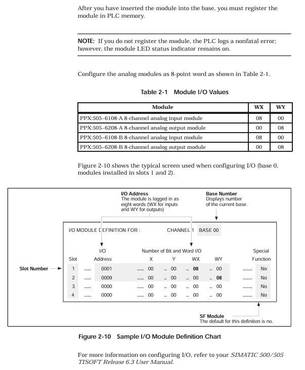
Module registration: Select the base number and slot number in the "I/O Module Definition Table", configure the module type and I/O parameters (Table 2-1):
|Module model | WX (number of input words) | WY (number of output words)|
| PPX:505–6108A | 08 | 00 |
| PPX:505–6108B | 08 | 00 |
| PPX:505–6208A | 00 | 08 |
| PPX:505–6208B | 00 | 08 |
Address allocation: The system automatically assigns I/O addresses (such as the input module address for slot 1 starting from WX0001), which are downloaded to the controller after configuration is complete;
Verify configuration: After powering on, observe the "Module Good LED" of the module. If the LED lights up, it indicates that the configuration is successful and the module has no faults.
Calibration and maintenance process
5.1 Basic Requirements for Calibration
5.1.1 Calibration cycle and conditions
Calibration cycle: It is recommended to calibrate every 6-12 months; If the module is used in high temperature and vibration environments for a long time, or if the measurement accuracy exceeds the tolerance, it needs to be calibrated immediately;
Environmental conditions: The calibration environment temperature is 25 ℃± 2 ℃, with no vibration or electromagnetic interference. The module reaches working temperature after being powered on for 30 minutes;
Tool preparation:
Calibration power supply: DC voltage source with an accuracy of ≥ 0.01% (used for input module calibration);
Measurement tool: a multimeter with an accuracy of ≥ 0.1% (for voltage/current measurement);
Load resistance: 5.1k Ω± 5% (voltage output calibration), 100 Ω± 5% (current output calibration);
Auxiliary tools: non-metallic screwdriver (to avoid short circuits), Euro extender card (optional, convenient for accessing potentiometers).
5.1.2 Calibration precautions
Disconnect the on-site wiring before calibration, leaving only the connections between the module, controller, and calibration equipment;
The controller needs to switch to "STOP mode" to avoid interference with calibration during operation;
The input module needs to first select the voltage range (jumper setting ± 5V or ± 10V) before calibration;
During the calibration process, avoid touching the module circuit board to prevent static damage or short circuits.
5.2 Input module calibration steps (PPX: 505-6108A/6108B)
Power off preparation: Turn off the controller power, disconnect the module field wiring. If using Euro extender card, remove the module first, insert the card, and then install the module onto the card;
Range selection: Select the calibration voltage range (± 5V or ± 10V) through the jumper on the module circuit board;
Power on preheating: Turn on the controller power and wait for 30 minutes for the module to reach operating temperature;
Device connection: Connect programming devices and controllers to ensure that module input data can be read; Connect the calibration voltage source to all input channels of the module;
Full range calibration (positive direction):
Input+5V (± 5V range) or+10V (± 10V range) to all channels;
Adjust the calibration potentiometer on the module circuit board with a non-metallic screwdriver until the programming device displays an average of+32000 for all channel numbers;
Full range calibration (negative direction):
Input -5V (± 5V range) or -10V (± 10V range) to all channels;
Adjust the potentiometer until the average digital value of all channels is -32000;
Accuracy verification: Enter+5V/+10V again to verify the numerical deviation:
PPX: 505-6108A: allowable deviation of ± 129/± 128;
PPX: 505-6108B: allowable deviation of ± 81/± 80;
Restore wiring: After calibration is complete, power off, remove the calibration equipment, restore on-site wiring and module installation positions, and reconfigure I/O addresses.
5.3 Calibration steps for output module (PPX: 505-6208A/6208B)
Power outage preparation: Turn off the controller and user power, disconnect the module load from the on-site wiring, and retain the user power wiring;
Load connection: Connect calibration loads to all output channels of the module (voltage channel connected to a 5.1k Ω resistor, current channel connected to a 100 Ω resistor);
Power on preheating: Turn on the controller and user power, wait for 30 minutes for the module to reach operating temperature;
Device connection: Connect programming devices and controllers to ensure that digital data can be written to the module;
Full range output: Write a digital quantity of 32000 to all channels (corresponding to 10V/20mA full range output);
Reference channel selection: Measure the current output values of all channels, calculate the average value, and select the channel with the output value closest to the average value as the reference;
Current calibration: Use a non-metallic screwdriver to adjust the calibration potentiometer so that the reference channel current output is 20.000mA (25 ℃);
Accuracy verification:
Voltage output: All channels must be 10.000V ± 50mV;
Current output: All channels must be 20.00mA ± 0.1mA;
If the deviation exceeds the tolerance, repeat steps 6-8;
Restore wiring: After calibration is completed, power off, remove the calibration load, and restore on-site wiring and module configuration.
5.4 Daily maintenance and troubleshooting
5.4.1 Key points of daily maintenance
Cleaning module: Clean the module panel and terminal block with a dry soft cloth every 3 months to avoid dust accumulation;
Wiring inspection: Check the tightening of terminal block screws every 6 months to prevent loose wiring caused by vibration;
Power inspection: Regularly check the user power supply (20-28VDC) of the output module to ensure that the ripple is ≤ ± 0.4VDC;
Fuse maintenance: When the output module fuse (0.5A fast melting, model PPX: 2587679-8009) burns out, it is necessary to first investigate the cause of overvoltage/overcurrent before replacing the fuse.
5.4.2 Common troubleshooting
Possible causes of malfunction, troubleshooting steps, and solutions
Module Good LED not lit (input module) Base power failure, module self diagnosis failure 1. Measure whether the base power supply voltage is normal; 2. Check if the module is correctly inserted into the slot; 3. Disconnect all wiring and reinstall. 1. Repair the power supply of the base; 2. Re plug and unplug the module; 3. Module self diagnosis failure requires return for repair
Module Good LED not lit (output module) Base power failure, user power failure, blown fuse, self diagnosis failure. 1. Measure the base and user power supply; 2. Check the status of the fuse; 3. Check if the module wiring is short circuited. 1. Repair the power supply; 2. Replace the fuse; 3. After eliminating the short circuit, power on again; 4. Self diagnosis failure requires return for repair
Input module reading error, wiring error, signal noise, calibration deviation, signal source out of range. 1. Check the wiring by referring to the pin diagram; 2. Check if the grounding of the shielding layer is correct; 3. Verify whether the output of the signal source is within ± 5V/± 10V or 0-20mA; 4. Recalibrate module 1. Correct wiring; 2. Optimize shielding and wiring; 3. Adjust the signal source to the effective range; 4. Complete calibration
The output module outputs abnormal loads beyond the range, digital input errors, calibration deviations, and unstable user power supply. 1. Measure whether the load resistance/capacitance meets the requirements; 2. Check if the digital output of the controller is correct; 3. Recalibrate the module; 4. Measure the user's power ripple. 1. Replace the load that meets the requirements; 2. Repair the digital output of the controller; 3. Complete calibration; 4. Replace the stable power supply
PLC reports non fatal module configuration error, module and controller communication failure. 1. Check the I/O configuration parameters (WX/WAY quantity); 2. Check if the module is in good contact with the base; 3. Restart the controller. 1. Correct the configuration parameters; 2. Re plug and unplug the module; 3. If the error persists after restarting, it needs to be returned for repair
Environmental and Safety Parameters (Appendix B)
6.1 Environmental adaptation parameters
Parameter indicators
Working temperature 0-60 ℃ (32-140 ℉)
Storage temperature -40-70 ℃ (-40-158 ℉)
Relative humidity 5% -95% (non condensing)
Vibration resistance sinusoidal vibration: 10-57Hz, 0.15mm peak to peak value; Random vibration: 57-150Hz, 1.0g
Impact resistance meets the IEC 68-2-27 Test Ea standard
Electrostatic Discharge (ESD) IEC 801-2 Level 4 (15kV)
Electromagnetic compatibility (EMC) conducted immunity: IEC 801-4 Level 3; Radiation immunity: IEC 801-3 Level 3
1500Vrms between the isolation voltage field and the controller
All components of corrosion protection are treated with corrosion-resistant materials, coatings, or spray paint
6.2 Safety Regulations
Overvoltage protection: Input module ± 30VDC, output module 30VDC;
Overcurrent protection: Input module 30mA, output module protected by fuse (0.5A);
Hazardous area use: Complies with ATEX Class I Div.2 standards and can be used in flammable dust environments (must meet dust explosion prevention requirements);
Wiring safety: The rated voltage of signal cables should be ≥ 300V, avoid mixing with power cables, and prevent insulation breakdown.
- YOKOGAWA
- Reliance
- ADVANCED
- SEW
- ProSoft
- WATLOW
- Kongsberg
- FANUC
- VSD
- DCS
- PLC
- man-machine
- Covid-19
- Energy and Gender
- Energy Access
- Renewable Integration
- Energy Subsidies
- Energy and Water
- Net zero emission
- Energy Security
- Critical Minerals
- A-B
- petroleum
- Mine scale
- Sewage treatment
- cement
- architecture
- Industrial information
- New energy
- Automobile market
- electricity
- Construction site
- HIMA
- ABB
- Rockwell
- Schneider Modicon
- Siemens
- xYCOM
- Yaskawa
- Woodward
- BOSCH Rexroth
- MOOG
- General Electric
- American NI
- Rolls-Royce
- CTI
- Honeywell
- EMERSON
- MAN
- GE
- TRICONEX
- Control Wave
- ALSTOM
- AMAT
- STUDER
- KONGSBERG
- MOTOROLA
- DANAHER MOTION
- Bentley
- Galil
- EATON
- MOLEX
- Triconex
- DEIF
- B&W
- ZYGO
- Aerotech
- DANFOSS
- KOLLMORGEN
- Beijer
- Endress+Hauser
- schneider
- Foxboro
- KB
- REXROTH
- YAMAHA
- Johnson
- Westinghouse
- WAGO
- TOSHIBA
- TEKTRONIX
- BENDER
- BMCM
- SMC
- HITACHI
- HIRSCHMANN
- XP POWER
- Baldor
- Meggitt
- SHINKAWA
- Other Brands
- UniOP
- KUKA
- IBA
- Beckhoff
-
Basler Electric DECS-250-CN1SN1N Automatic Voltage Regulator for Generator Excitation Control
-
ADLINK CPCI-6860A - 51-31310-OB10 industrial motherboard CompactPCI SBC
-
ADLINK AmITX-SL-G-H110 - 51-7A104-0A30 Mini-ITX Industrial Motherboard
-
ADLINK PXI-2005-003 - CPCI Industrial PC Data Acquisition Card Multi-Function DAQ
-
ADLINK DININ-814M - 51-14032-0A3D SCSI-100P cable connection Interface Terminal Board
-
ADLINK CPCI-3920NA/C2D15/M1G - 3U CompactPCI Intel Core 2 Duo Single Board Computer
-
ADLINK PCIE-8560 - 51-18014-0A20 Communication Card High Speed DAQ
-
ADLINK PCI-C154+ - Motion Control Card 4-axis Motion Controller Board
-
ADLINK PCI-RTV24 - image capture card Analog Video Frame Grabber
-
ADLINK NuPRO-842LV/P - 51-41360-0B30 Industrial Motherboard CPU Board
-
ADLINK cBP-3208/3208R - CPCI Board 3U 8-Slot CompactPCI Backplane
-
ADLINK PCI-8164 - 4-Axis Motion Controller PCI Card 51-12406-0A40
-
ADLINK PCIe-GIE64+ - 4-CH GigE Vision PoE+ Frame Grabber Video Capture Card
-
ADLINK CPCI-6860 / 6860A - CompactPCI Dual Xeon Single Board Computer
-
ADLINK IEC-915GV - REV 1.1 Industrial motherboard CPU Board
-
ADLINK ND-6520 - Technology RS-232 to RS-422RS-485 Converter NuDAM Module
-
ADLINK RTV-24 / PCI-MP4S - 51-12519-1C30 4-Channel Real Time Video Capture Board
-
ADLINK cPCI-6910 / cPCI-6910AM/M1G - cPCI-6910AM/DXL16/M1G/S80G(G)-3120 BOARD CompactPCI SBC
-
ADLINK NUPRO-A40H - Linghua 51-41807-1A30 Industrial Control Computer Motherboard
-
ADLINK USB-3488A - USB to GPIB INTERFACE USB-3488A(G) Controller Module
-
ADLINK PCI-8134A - motion control card 4-Axis Controller Card
-
ADLINK PCI-7432 - Board 32-Channel input / 32-output Isolated Digital I/O PCI Card
-
ADLINK PCI-8134A - 51-12421-0A10 motion controller card tested
-
ADLINK LPCIe-7230 - 32 CH Isolated Input/output Card 2 Interrupts Low Profile PCIe
-
ADLINK NuPRO-E340 - industrial computer motherboard 51-47807-0A30 PICMG 1.3 SHB
-
ADLINK PCI-7434 - High-speed Digital Acquisition Card 64-CH Isolated DO Card
-
ADLINK NuPRO-E330 - 51-41805-0A20 Indsutrial Board SHB Single Board Computer
-
ADLINK PCI-7248 - OPTO-22 48 CHANNEL DIO DIGITAL TTL/DTL I/O 51-12006-0A40 GP
-
ADLINK PCI-8134 - Motion control card 4-Axis Controller Card
-
ADLINK AMP-208C - Movimiento Control Tarjeta 51-12420-1A20 W/Expansión & Breakout
-
ADLINK PCI-8164 - 51-12406-0A40 PCB Board 4-Axis Motion Controller Card
-
ADLINK DIN-68Y-SGII / DIN-68M-J3A - Terminal Board Connector Interface Block
-
ADLINK PCIe-7432 - Technology 51-18402-0A10 PCIe Card With High Input Range
-
ADLINK PCI-8144 / PCI-8144N - Motion control card 4-Axis Stepper Controller Card
-
ADLINK HSL-HUB3/REPEATER - HIGH SPEED LINK EXTENSION MODULES Distributed Hub Module
-
ADLINK ND-6017 - Data Logging + Acquisition 8CH A/D input Mod NuDAM Module
-
ADLINK LPCIe-7250 - data acquisition card Low Profile 8-CH Relay Output Card
-
ADLINK PCI-7432 - I/O card 64-CH Isolated Digital Input Output PCI Card
-
ADLINK IMB-M43H - industrial control computer motherboard Q87 Chip Micro-ATX
-
ADLINK MP-C154 - Motion control Card 4-Axis Motion Controller Board
-
ADLINK PCI-RTV24 - image capture card Video Frame Grabber Card
-
ADLINK PCI-7250 - 8-CH Relay Output & 8-CH Isolated DI Card
-
ADLINK PCI-6308V - 8-CH 12-Bit Isolated Analog Output PCI Card PCB-I-E-1148=6EX2
-
ADLINK PCI-7248 - capture card 48-CH Opto-22 Compatible DIO Card
-
ADLINK HSL-AI16A02-M-VV - Analog Input Output Distributed Module
-
ADLINK NuPRO-A301 - Rev:1.4 NUPRO-A301 PICMG Full-Size Single Board Computer
-
ADLINK PCI-6208V-GL - 8-CH Voltage Analog Output PCI Card
-
ADLINK PCI-8134A - 51-12421-0A10 4-Axis Motion Controller Card
-
ADLINK MNET-S23 - TECHNOLOGY MNET S23 - SERVO DRIVER CONTROL MODULE
-
ADLINK M-342 - ATX I3 I5 I7 Q67 Industrial Motherboard
-
ADLINK NUPRO-780 - Industrial Motherboard CPU Board PICMG SBC
-
ADLINK MP-C154 / MP-C152 - 4-Axis Motion Control Card Pulse-Train Controller
-
ADLINK NuPRO-935A/LV10B0 - Motherboard 51-41802-0A10 GP w/RAM Industrial Control Board
-
ADLINK MP-C154 - Motion control card 4-Axis Motion Controller Mainboard
-
ADLINK PCI-7250 - PCI Acquisition Card 8-CH Relay Output Isolated DI Card
-
ADLINK ACL-7124 - Technology Inc.24 DIO Card Digital Input Output Card
-
ADLINK PCI-8554 A2 - Timer/Counter Data Acquisition Card
-
ADLINK DIN-825-GP4 - Terminal Block Interface Board Breakout Module
-
ADLINK NuPR0-761 - REV:1.1 Industrial motherboard Full-Size PICMG SBC
-
ADLINK MXE-1401/M8G (G) - Matrix Fanless Embedded Computer Industrial PC
-
ADLINK HSL-DI16DO16-UD-NN - Digital 16 Channel I/O Mod Distributed I/O Module
-
ADLINK ND6520 - NUDAM INTELLIGENT DA&C MODULE RS232-RS-422/RS485 CONVERTOR
-
ADLINK NUPRO-761 - REV:1.1 Industrial Motherboard CPU Board
-
ADLINK AMP-208C - Motion Control Card 51-12420-1A20 DSP-based 8-axis
-
ADLINK NuPRO-A301REV 1.4 - with packaging industrial computer motherboard PICMG SBC
-
ADLINK PCM-9112+ - 51-12300-0A2 industrial motherboard Multi-Function DAQ PC/104 Module
-
ADLINK PCM-7250+ - 8-CH Relay Outputs & 8-CH Isolated DI Module PC/104
-
ADLINK PCI-RTV24 - Image capture card Analog Video Frame Grabber
-
ADLINK PCI-8134 - Motion Controller PCI Card 4-Axis Controller Board
-
ADLINK PCI-7432 - Isolated Digital I/O PCI Card
-
ADLINK PCI-8554 A2 - acquisition card Timer/Counter Card
-
ADLINK PCI-8132 - Rev.A2 2-Axis Servo & Stepper Motion Controller Card
-
ADLINK PCI-8132 - Data Acquisition card 2-Axis Motion Controller Card
-
ADLINK EBP-13E4 - 51-46703-0A30 Industrial Backplane Board Passive Backplane
-
ADLINK PCI-800L - Electronic Card Interface Controller Card
-
ADLINK PCIe-GIE72 - 51-18531-0A10 PCB Board GigE Vision Frame Grabber
-
ADLINK DAQ-2010(G)-OOBO - Simultaneous-Sampling Multi-Function DAQ Card
-
ADLINK PCI-9112 - REV.B1 Multifunction DAQ Card Data Acquisition Card
-
ADLINK PCI-7230 - 51-12003-DA60 32-CH Isolated Digital I/O Card
-
ADLINK PCI-7432 - Data Acquisition Card Isolated Digital I/O PCI Card
-
ADLINK ETX-AT-N270-18/LXE - 51-71111-0A20 ETX CPU Module Motherboard
-
ADLINK HSL-DI32-UD-N - DIGITAL INPUT 32 POINTS MODULE Distributed I/O
-
ADLINK AMP-204C - Motion Control card DSP-Based 4-Axis Advanced Controller
-
ADLINK MNET-4XMOG-0050 - Four-axis Motion Controller Distributed Motion Module
-
ADLINK AMP-204C - Motion control card DSP-Based 4-Axis Pulse-Train Controller
-
ADLINK PCI-7442 - Switch card 64-Channel Datalogging & Acquisition Card
-
ADLINK M-302 - Industrial control motherboard ATX PC Board
-
ADLINK NUPRO-852 / NUPRO-852LV - Industrial motherboard Single Board Computer
-
ADLINK PCI-8134 - REV.B1. 4-Axis Motion Controller Card
-
ADLINK PCI-GIE62 + - 51-18502-0A20 2-CH GigE Vision Frame Grabber PoE Card
-
ADLINK PCI-MPG24 - 51-12523-0B20 MPEG4 Card Video Compression Hardware
-
ADLINK HSL-TB32-M-DIN - 32-CH I/O TERMINAL W/ HSL-AI16AO2-M-VV MODULE
-
ADLINK PCI-M114-GL - PCB Ver 2.1 Motion Controller Axis Card
-
ADLINK IMB-M40H - SYM76996H61 motherboard Industrial Computer Mainboard
-
ADLINK NUPRO-A40H - 51-41807-1A20 industrial control motherboard H61 Chip
-
ADLINK PCI-M114-GL - Axis Card Data Acquisition Card PCB VER2.2 Motion Controller
-
ADLINK PCI-8134 - Motion Controller PCI Card 4-Axis Controller Board
-
ADLINK PCI-8102 - Motion control card 2-Axis Servo & Stepper Controller
-
ADLINK NuPRO-841REV:3.0 - motherboard Industrial Control PC Board
-
ADLINK HSL-TB32-U-DIN REV A1 - Breakout Terminal Board Field I/O Module
-
ADLINK AMP-204C - Motion Control card DSP-Based 4-Axis Pulse-Train Controller
-
ADLINK NUPRO-A40H - 51-41807-1A20 industrial control motherboard H61 PC Board
-
ADLINK PCI-6308A / PCI-6308V - 51-12202-0A50 Isolated Analog Output Card
-
ADLINK AMP-204C - DSP-Based 4-Axis Advanced Pulse-Train Motion Controller
-
ADLINK PCI-7434 - Technology 64-Channel Isolated Digital I/O PCI Cards
-
ADLINK CPCI-6840 / CPCI-6840V / PM16/M1G-12G0 - CompactPCI Single Board Computer CPU Module
-
ADLINK PCIE-GIE74 - Motherboard Video Capture Card 51-18531-0A10 Frame Grabber
-
ADLINK NuPRO-E330 - industrial computer equipment motherboard Control Mainboard
-
ADLINK AMP-208C / 51-12420-1A20 - Motion Control Card W/ Expansion & Breakout Board
-
ADLINK HPCI-14S12U - industrial computer baseboard Passive Backplane 14 Slots
-
ADLINK PCI-8164 - 4-Axis Motion Controller PCI Card W/ 1x Cable, 1x Breakout Box
-
ADLINK PCIe-RTV24 - 51-18016-0A20 Image Acquisition Video Capture Card
-
ADLINK M-342 - 5 PCI ATX Motherboard Industrial PC Mainboard
-
ADLINK PCI-FIW64 - 4/2 Channel IEEE1394B Image Capture Card FireWire Frame Grabber
-
ADLINK PCI-7432 - digital IO card 64-CH Isolated Digital Input Output Card
-
ADLINK 51-12001-0C20 - Circuit Board PCI-7200 Data Acquisition Controller Card
-
ADLINK PXI-3920 - PXI 3U cPCI Industrial Controller Embedded System CPU Board
-
ADLINK NuPRO-841REV:2.0 - motherboard Industrial Control PC Board
-
ADLINK NuPro-E330 - 51-41805-0A20 PCB Industrial Control Computer Motherboard
-
ADLINK PCI-RTV24 - Image capture card Analog Video Frame Grabber
-
ADLINK PCI-7442 - Switch card 64-Channel Datalogging & Acquisition Card
-
ADLINK HPX-13S4 - device baseboard Passive Backplane Riser Card
-
ADLINK PCI-9112 REV A.1 - Multi Function DA&C Board Data Acquisition Card
-
ADLINK PCI-7248 - 51-12006-0A40 Card Control 48-CH Digital I/O Module
-
ADLINK CPCI-6860 / 6860A - motherboard CompactPCI Dual Xeon Single Board Computer
-
ADLINK DPAC-3020-11(G) - Embedded PC Automation Controller Machine Control Board
-
ADLINK NuPRO-841 REV:1.0 - industrial control motherboard CPU Board
-
ADLINK MNET-4XMOG-0050 - Four-axis Motion Controller MNET Motion Control Card

K-JIANG

Add: Jimei North Road, Jimei District, Xiamen, Fujian, China
Tell:+86-15305925923