
K-WANG


SIEMENS SIMOTICS L-1FN3 Linear Motor Operating Instructions
SIEMENS SIMOTICS L-1FN3 Linear Motor Operating Instructions
Overview
SIMOTICS L-1FN3 series permanent magnet synchronous linear motor operation guide, covering the entire life cycle process from receiving, installation to scrapping. The core information includes: the motor is a modular structure (including primary components, secondary components, and optional precision coolers/secondary coolers), with protection level of IP65 for primary components, minimum IP23 after installation, suitable medium temperature of * * -20... 220 ° C * * (special sealing letter needs to be replaced for low temperature), cooling method is water cooling (maximum pressure of cooling circuit is 10 bar), and needs to be used with SAX. electric actuators or SKD./SKB./SKC. electric hydraulic actuators; The manual emphasizes the safety risks of strong magnetic fields (the suction force of the secondary component permanent magnet can reach several kN, and those wearing pacemakers need to maintain a distance of ≥ 500mm), electrical connection specifications (must comply with SELV/PELV standards, and the shielding layer must be reliably grounded), and safe operation throughout the entire process. At the same time, it provides detailed guidance on mechanical installation dimensions, fault handling, maintenance, and waste disposal (secondary components need to be demagnetized at 300 ° C or above) to ensure the safe and stable operation of the motor.
Product Technical Characteristics
1. Basic parameter table
Parameter category specific specifications
Motor type: Permanent magnet synchronous linear motor
Modular structural form (primary components: including 3-phase winding+main cooler; secondary components: permanent magnet+steel base; optional precision cooler/secondary cooler)
Protection level for primary components: IP65 (compliant with DIN EN 60034-5); Motor after installation: minimum IP23 (determined by machine design)
Cooling method: Water cooling (maximum pressure of cooling circuit is 10 bar, interface is G1/8 pipe thread, in accordance with DIN ISO 228-1)
Thermal protection primary component with built-in 1 PTC thermistor (response threshold+120 ° C, compliant with DIN 44081/44082, Temp-S circuit)
Temperature monitoring Temp-F circuit (1FN3xxx-xxxx-xxx1 with KTY84 sensor, 1FN3xxx-xxxx-xxx3 with Pt1000 sensor)
Insulation Class Thermal Class 155 (F Class, compliant with EN 60034-1)
Electrical interface 1FN3050: Fixed cable (with/without connector); 1FN3100-1FN3900: Integrated connector+cover plate
2. Environmental and adaptation requirements
Temperature range:
Conventional: -5... 220 ° C; Low temperature: -20... 150 ° C (special sealing letter needs to be replaced: DN15... 50 is 428488060, DN65... 150 is 467956290)
Storage/transportation temperature: -5... 40 ° C (condensation and freezing are not allowed)
Rating reduction factor: When the installation height is greater than 2000m, the voltage needs to be reduced (such as 0.877 for 3000m and 0.656 for 5000m)
Adaptive actuator: It needs to be selected according to the driving force and stroke, as shown in the following table:
Applicable scenarios for actuator series driving force stroke
SAX. 800N 20mm DN ≤ 50 motor, light load
SKD. 1000N 20mm DN ≤ 50 motor, high load
SKB. 2800N 20mm DN ≥ 65 motor
SKC. 2800N 40mm DN ≥ 65 motor, large stroke requirement
Core safety requirements
1. Strong magnetic field safety (highest priority)
Risk point: The secondary component contains permanent magnets, and there is still a strong magnetic field in the power-off state. The suction force can reach several kN (equivalent to squeezing hundreds of kg of heavy objects), and the magnetic field strength can reach 3mT at a distance of 150mm (in accordance with Directive 2013/35/EU)
Safety measures:
Individuals wearing pacemakers/insulin pumps must maintain a distance of ≥ 500mm;
The installation of secondary components requires at least 2 people to work, wear gloves, prepare 3kg non-magnetic hammers and 10 ° -15 ° hardwood wedges (anti extrusion rescue);
Only remove the packaging of secondary components before installation, and it is forbidden to remove multiple packages at the same time. Do not place them side by side when they are not fixed;
It is prohibited to bring magnetic items (watches, steel tools) into the secondary component sensing area.
2. Electrical safety
Power requirements: Only allow connection to SELV (safe low voltage) or PELV (protective low voltage) power supply;
Induced voltage risk: When the primary and secondary components move relative to each other, the cable interface will generate induced voltage, which needs to be operated after power-off. It is forbidden to touch uninsulated interfaces;
Grounding and shielding:
Equipment with protection level I must be reliably grounded (to prevent contact voltage);
At least one side of the cable shielding layer is grounded through the grounding shell, and unused core wires need to be insulated or grounded;
The shielding layer of the power cable needs to be connected to the power module over a large area, and the protective grounding wire (PE) should be directly connected to the power module to prevent high discharge current from damaging the equipment.
3. Safe operation
Cooling system: No operation without cooling is allowed (overheating can cause the cooling water to vaporize and burst the pipes). The cooling circuit can only be connected after the motor has cooled down;
High temperature protection: The surface temperature of the motor during operation may exceed 100 ° C, and a "Hot Surface Warning" label should be affixed. During maintenance, it should be cooled down or protective gloves should be worn;
Unexpected operation: During debugging, it is necessary to limit the current and speed, ensure smooth travel, and keep personnel away from the operating/squeezing area.
Full process operation guide
1. Preparation for use (transportation and storage)
Transportation requirements:
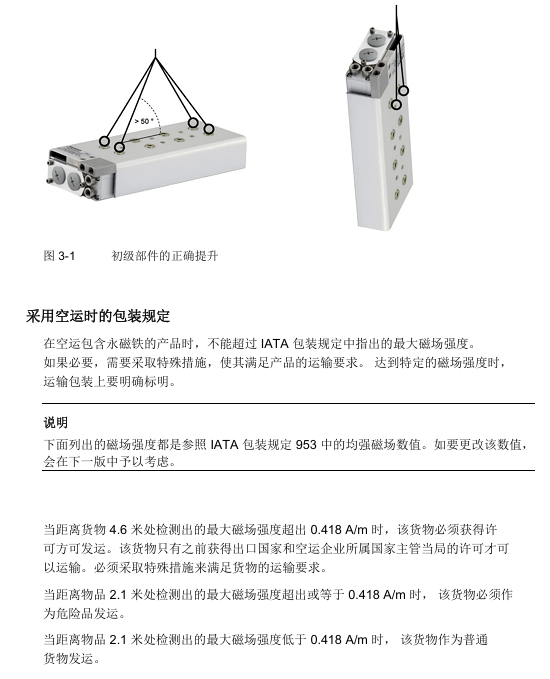
Shipping/Highway: No additional magnetic field protection required;
Air freight: In accordance with IATA regulations, two secondary components must be stacked in opposite directions (offset<1cm), otherwise they must be transported as dangerous goods (magnetic field>0.418A/m at a distance of 2.1m);
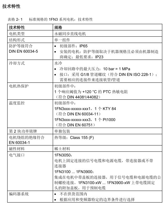
Lifting: Primary components require lifting eye bolts (in accordance with DIN 580), with a horizontal lifting angle of ≥ 50 ° and a center of gravity perpendicular to the hook.
Storage requirements:
Environment: 1K3 level (temperature -5... 40 ° C, humidity 5% -85%, no condensation/vibration);
Duration: Up to 2 years, exposed parts without anti-corrosion agents need to be coated with Tectyl, and the cooling system needs to be emptied and blown with dry compressed air.
2. Mechanical installation
Fixed specifications:
Screw: Grade 10.9 brand new screw, tightening torque must meet the standards (M5=7.6Nm, M6=13.2Nm, M8=31.8Nm);
Surface: The fixed surface needs to be free of oil/grease/paint, with a surface roughness Rz of 10-40 μ m;
Screw in depth: It must comply with the minimum (e.g. 1.8 × d for St 37 material) and maximum limit (calculated by the machine tool manufacturer).
Installation steps:
Check the installation dimensions (installation dimension error of ± 0.3mm for different configurations of heavy-duty/long-term motors);
Clean the installation surface and install secondary components (tighten the screws in the prescribed order, with all "N" markings facing the same direction);
Install primary components (note to align with the "N" mark on the secondary components, and ensure that the fixing screws are screwed in to the correct depth);
Inspection: The slider needs to move flexibly (force fluctuations caused by tooth groove force are normal), and the air gap (0.5mm film with cover plate and 1.0mm film without cover plate, which should be able to move easily).
3. Connection (cooling and electrical)
Cooling circuit connection:
Material: Brass/stainless steel is recommended for the coolant interface, and the hose should be resistant to coolant (Festo/Rectus brand is recommended);
Circuit: It is recommended to have an independent circuit, and ensure that the inlet temperature of each primary component is consistent when connected in parallel. Flexible hoses should be used for connection (to prevent rigid connection seal failure);
Coolant: Water containing anti-corrosion agent (chloride/sulfate<100mg/l, pH=6.5-9.5), recommended 25% -30% ethylene glycol mixture (freezing point ≤ -5 ° C).
Electrical connection:
Cable specifications: 4-core power cable (core wire cross-section ≥ 2.5mm ², 2.5mm ² corresponds to maximum rated current of 21A), 4-core signal cable (cross-section 0.5mm ²);
Pin layout: The power interface is U/V/W/PE, and the temperature sensor interface needs to distinguish between PTC (Temp-S) and KTY84/Pt1000 (Temp-F). The core wire color needs to match (such as - KTY/Pt1000 for white and+KTY/Pt1000 for black);
Shielding treatment: Signal/power cables need to be wired separately, and the shielding layer should be grounded extensively (using clamps/clamps).
4. Debugging
Prerequisite: Complete mechanical installation, electrical/cooling connections, and have drive system documentation;
Key steps:
Checklist confirmation (general: complete components/complete documentation; mechanical: smooth travel/compliant air gap; electrical: correct grounding/shielding);
Insulation resistance test: Test with 1000V DC for 60 seconds, insulation resistance ≥ 10M Ω (between winding and PE, temperature sensor and PE);
Cooling system inspection: Ensure that the coolant meets the requirements, the circuit is leak free, and the pressure is ≤ 10 bar;
Trial operation: Limit current and speed, check commutation (phase sequence U-V-W is positive direction), monitor temperature sensor signal.
5. Operation and maintenance
Operation monitoring: It is necessary to monitor abnormalities (such as noise, heat, current rise, vibration), and immediately stop the machine for troubleshooting (see the table below for fault codes and handling);
Fault Handling Table:
Possible causes (code) of the fault phenomenon and remedial measures
Motor lock A (overload), B (phase loss) to reduce load, check frequency converter and feeder line
Abnormal noise during operation D (reversing fault), K (foreign object) detection of reversing angle, cleaning of air gap foreign objects
Abnormal no-load heating F (cooling not connected), G (insufficient water volume), connect cooling, check cooling water volume/inflow temperature
Slow shaft response E (winding short circuit), L (poor alignment), check winding resistance, and re align machine guide rail
Maintenance requirements: There is no regular maintenance cycle, and the following situations require maintenance: foreign objects around the motor, machine abnormalities (visual/auditory), decreased positioning accuracy, and increased current; During maintenance, power off and cool down for 30 minutes, clean the air gap chips/dust, and check the cable shielding layer.
6. Scrapping and waste disposal
Dismantling steps: In reverse order of installation, power off and discharge first → cool for 30 minutes → disconnect cooling → clamp cable → drain coolant → remove primary components → remove secondary components;
Waste disposal:
Secondary components: Professional enterprises are required to use a furnace with a temperature of ≥ 300 ° C to demagnetize for at least 30 minutes, collect and treat exhaust gas;
Material classification: electronic waste (encoder/winding/cable), iron waste (iron core), aluminum, insulation materials;
Packaging: Recyclable materials (PE-HD/PE-LD/PP/PS) recycling, wood is combustible.
Appendix and Support
Manufacturer recommendations: corrosion inhibitors (Tyfocor, Antifrogen N), cooling connectors (Rectus), plastic hoses (Festo/Rectus), distance film (SAHLBERG);
Abbreviations: Temp-S (over temperature cut-off monitoring circuit), Temp-F (temperature observation circuit), HSB (Hall sensor box), PE (protective grounding);
Additional guidance: Installation size of Hall sensor box (fixed position and spacing for different motor models, such as 35mm distance between HSB and primary components of 1FN3050-150 motor).
- YOKOGAWA
- Reliance
- ADVANCED
- SEW
- ProSoft
- WATLOW
- Kongsberg
- FANUC
- VSD
- DCS
- PLC
- man-machine
- Covid-19
- Energy and Gender
- Energy Access
- Renewable Integration
- Energy Subsidies
- Energy and Water
- Net zero emission
- Energy Security
- Critical Minerals
- A-B
- petroleum
- Mine scale
- Sewage treatment
- cement
- architecture
- Industrial information
- New energy
- Automobile market
- electricity
- Construction site
- HIMA
- ABB
- Rockwell
- Schneider Modicon
- Siemens
- xYCOM
- Yaskawa
- Woodward
- BOSCH Rexroth
- MOOG
- General Electric
- American NI
- Rolls-Royce
- CTI
- Honeywell
- EMERSON
- MAN
- GE
- TRICONEX
- Control Wave
- ALSTOM
- AMAT
- STUDER
- KONGSBERG
- MOTOROLA
- DANAHER MOTION
- Bentley
- Galil
- EATON
- MOLEX
- Triconex
- DEIF
- B&W
- ZYGO
- Aerotech
- DANFOSS
- KOLLMORGEN
- Beijer
- Endress+Hauser
- schneider
- Foxboro
- KB
- REXROTH
- YAMAHA
- Johnson
- Westinghouse
- WAGO
- TOSHIBA
- TEKTRONIX
- BENDER
- BMCM
- SMC
- HITACHI
- HIRSCHMANN
- XP POWER
- Baldor
- Meggitt
- SHINKAWA
- Other Brands
- UniOP
- KUKA
- IBA
- Beckhoff
-
LTI SC52.0040.0012.0000.0 - Servo Drive
-
Lti SC52.0040.0012.0000.0 - Servo Drive
-
Milton Industries LTI Tool By Milton LT1240 - 1/2" Drive Lugnut Remover
-
LTi Drives SO84.200.P030.0000.0-W - Servo Spindle Drive
-
LTI DRIVES LSP08-035-320-30-B0R1PY170 - Servo Motor
-
LTI DRIVES SE84.200.SC00.0001.0-W - Servo Drive
-
Lust CDE34.005.W2.2 - Lti Drives Controller
-
LTi SO84.012.0030.0011.2 - ServoOne Servo Drive
-
LTi Drives SO CM-P.0010.11.00.0 - Servo Drive Controller
-
LTi CDE34.017.W3.0 - Servo Drive
-
LTI Drives CDB32.004, C2.0,SH - Positioning Controller
-
LUST CM-CAN1 - LTi DRIVES Communication Module
-
LTi SO84.012.1030.0000.2 - Servo Drive
-
LTI MOOG CDE54.044 - PITCHMASTER FREQUENCY CONVERTER 181-01019
-
MOOG LTI 181-01019 CDE54.044 - PITCHMASTER FREQUENCY CONVERTER
-
Lust LTi Drives CDE34.010,D2.0 - Servo Drive Controller
-
LTI SO84.032.0003.0101.2 - Servo Drive
-
Seagate 9CC132-302 Harris LTI-CS IRT-34-0021-01 - Hard Drive 160GB
-
LTI SO84.032.0003.0001.2 - Servo Drive
-
LTI SO24.007.0070.0000.1 - SERVO CONTROLLER
-
LTi drive CDA32.003.C3.0.H05-01.PC1 - Servo Drive
-
LTI SO84.016.0030.0000.2 - SERVO CONTROLLER
-
LUST LTI CD A34.008,W1.4, BR - SERVO DRIVE
-
MOOG LTI 181-01019 CDE54.044 - PITCHMASTER FREQUENCY CONVERTER
-
LTI MOOG 181-01019 - PITCH Master Servo Drive CDE54.044
-
LTI SERVO ONE SO84.045.0030.0001.2-W - Drive
-
LUST LTi SO84.032.0040.0000.2 - SERVO ONE DRIVE
-
LTi Drives LSH-074-2-30-3 20/T1,G6.1M - SERVO MOTOR
-
LTI SO84.016.0000.0101.2 - servo drive
-
LTI SA54.0550.0033.0000.0 - Servo Drive
-
LTI SA54.0550.0033.0000.0 - Servo Drive
-
LTI LT 4850 - 3/8" Drive 3-Pc Twist Socket Transmission Drain Plug Removal System
-
LTI Tools LT4400-30 Lock Technology - 3/4" Twist Socket 1/2" Drive Lugnut Remover
-
LTI Tools LT-1400C - 1/2 Drive Wheel Torque Extension Tool
-
LTI Tools LT1250 - 1/2" Drive Dual Sided Socket Lug Nut Remover Tool
-
LTI SO84.032.0003.0101.2 - Servo Drive
-
LTI MOOG 181-01019 - PITCH Master Servo Drive CDE54.044
-
MOOG LTI 181-01019 CDE54.044 - PITCHMASTER FREQUENCY CONVERTER
-
MOOG LTI 181-01019 CDE54.044 - PITCHMASTER FREQUENCY CONVERTER
-
MOOG LTI 181-01019 CDE54.044 - PITCHMASTER FREQUENCY CONVERTER
-
LTI SA54.0550.0033.0000.0 - Servo Drive
-
LTI Tools LT-4800 - 7 Piece Twist Socket 3/8" Drive Oil Drain Plug Removal Set
-
LTI SA54.0550.0033.0000.0 - Servo Drive
-
LTI Drive SO24.007.00300000.0 - Servo Drive
-
LTI TOOLS LTI 1400-I - Drive Wheel Torque Extension
-
LTI Tools LT4400-3 - 3/4" 19mm Twist Socket 1/2" Drive Lugnut
-
LTI TOOLS LTI 1400-BB - Drive Wheel Torque Extension
-
LTI SO84.032.0003.0101.2 - Servo Drive
-
LTI Tools LT-4512 - 3/8" Drive 12mm Twist Socket
-
LTI MOTION Luster SO84.032.0003.0001.2 - Servo Drive
-
LTI Tool By Milton LT1600P - 1" Drive Torx Stick
-
LTI Lust VF1424L,HF,OP2,S56 - Variable Frequency Drive
-
LUST CDA32.004,C1.4,H08,B0 - SERVO DFRIVE CM-CAN1 Module
-
LTI SO84.045.0002.0001.2-W - Drive
-
LTI Lust VF1404M,C9,PT1,BR1 - Inverter Type VF1404M
-
LTI SA54.0550.0033.0000.0 - Servo Drive
-
LTI Tools LT-1400C - 1/2" Drive Wheel Torque Extension
-
Lust LTI DRiVES CDA32.006, C3.0, H09 - Variateur De Fr茅quence Frequency Inverter
-
LTI MOOG CDE54.044 - PITCH master SERVO DRIVE
-
LTI MOOG CDE54.044 - PITCH master SERVO DRIVE
-
LTI SO84.143.0020.0101.2-W - servo drive
-
LTI MOTION SC34.0200.0011.0000.0 - Servo drives
-
LTI SO84.032.0003.0001.2 - Servo Drive
-
LTI DRIVES GmbH MS100 - Assembly Set Mounting Kit
-
LTI SO84.032.0003.0001.2 - Servo Drive
-
LTI SO84.032.0003.0001.2 - Servo Drive
-
LTI MOTION SO84.032.0003.0101.2 - servo drive
-
LTI SO84.032.0003.0101.2 - Servo Drive
-
LTI MOOG CDE54.044 - PITCH master SERVO DRIVE
-
LTI MOTION CDE32.004.C2.4 - Servo drives
-
LTI CDD34.032锛學x.x锛孊R锛孭C1 - Servo Drive
-
Lust LTI DRiVES CDA32.006, C3.0, H09 - Inversor De Frecuencia Frequency Inverter
-
Lust SO84.008.0030.1000.0 - Servo One LTi Drive
-
LTI MOTION SO84.032.0003.0101.2 - Servo drives
-
LUST LTi CDA32.004,C1.4 - SERVO DRIVE
-
LTI MOOG CDE54.044 - PITCH Master SERVO DRIVE
-
LTI KEBA CDB32.004 C2.7, SH - PN: 08673530 Frequency Inverter
-
LTI Tools LT-1400C - 1/2" Drive Wheel Torque Extension
-
LTI LT1400-E - 1/2" Drive Wheel Torque Extension
-
LTI MOOG 181-01019 - PITCH master SERVO DRIVE CDE54.044
-
LTI LSN-097-0510-30-560/T1 - Actuator Motor
-
LTI Tools LT 4800 - 7 Piece 3/8" Drive Twist Socket Oil Drain Plug Removal System
-
LTI DRIVES GmbH MS100 - MONTAGESET Assembly Set Mounting Kit
-
Lti SC52.0040.0012.0000.0 - Servo Drive
-
LTI DRIVES GmbH MS100 - Juego De Montaje Assembly Set Mounting Kit
-
LTi DSM4-14.2-21R83-200 - Drives servomoteur Servo Motor
-
MOOG CDE 54.044.GDA - Pitch Master Industrielle Turbine Lti Drive
-
LTI SO24.004.0030.1000.0 - Servo Drive Controller
-
Lti MOOG CDE54.044 - Pitch Master Servo Drive
-
Lust LTI DRiVES CDA32.006, C3.0, H09 - Inverter
-
LTI MOTION GMBH CDB34.006,W3.0,PC1,H39 - Frequency inverter
-
LTI SO84.032.0003.0001.2 - Servo Drive
-
MOOG CDE 54.044.D - Pitch Master Industrielle Turbine Lti Drive
-
LTI TOOLS LT-1460 - 1/2" DRIVE WHEEL TORQUE EXTENSION KIT 5 PIECE SET
-
Lust Cdb32.003, C2.4 - Lti Drives Servoregulador Frecuencia Servo Controller Inverter
-
Lust LTI DRIVES CDA32.006, C3.0, H09 - Frequency Inverter
-
Lust Lti SO82.004.0030.0000.2 - Servo Drive
-
LTI MOTION SC34.0200.0011.0000.0-SL - Servo drives
-
LTI MOTION SA54.0075.0033.0000.0 - Servo drives
-
LTI MOTION SC32.0075.1011.0000.0 - Servo drives
-
Lust Cdb32.003, C2.4 - Lti Drives Servo Controller Frequency Inverter
-
LTI MOOG CDE54.044 - PITCH master SERVO DRIVE
-
Lust Lti Cde34.006,W2.0,Br - Servo Drive
-
Lust LTi MOTION CDE34.044,W2.4,H13 - Servo Drive
-
Lust LTi Drives Cde32.008, W2.2.br - Positionierregler Posici贸n Mando Positioning Controller
-
LTI MOOG CDE54.044 - PITCH master SERVO DRIVE
-
LUST Antriebstechnik B-DS 125.1 - LTi DRiVES Accessories Drive Component
-
LTi LSMM13-100-4N-001 - servo motor
-
Lti CDA32.004 C1.4, H08, B0 - PN: 3084456 Frequency Inverter
-
LTI MOTION CDE34.006.WXX.PC1 - Servo drives
-
LTI MOTION SO24.007.0030.1000.0 - Servo drives
-
Lust CDD34.005.C2.1 - LTI Drive
-
Lti SC52.0040.0012.0000.0 - Servo Drive
-
LTI Tools LT4400-30 - 1/2" Drive 19mm 3/4" Twist Socket
-
Lust LTi Drives Cde32.008, W2.2.br - Positionierregler Posici贸n Mando Positioning Controller
-
LTI MOOG CDE54.044 - PITCH master SERVO DRIVE
-
LUST Antriebstechnik B-DS 125.1 - LTi DRiVES Accessories Drive Component
-
LTI DRIVES GmbH MS100 - MONTAGESET Assembly Set Mounting Kit
-
Lust LTi SO84.032.0043.0000.2 - Servo one Drive
-
LUST LTi Drives CM-CAN1 - Modulo Di Comunicazione Communication Module
-
LTI drive CDF 30.008.C3.6 - Servo Drive
-
LTI MOOG 181-01019 - PITCH master SERVO DRIVE
-
LTI CDB34.014,W2.4,BR,SH - Servo Driver
-
Lti SC52.0040.0012.0000.0 - Servo Drive
-
LTi Drive CDF30.002 - Power Supply Fuse
-
LTI Tools LT-4621-D - Deep Well Twist Socket 3/8" Drive 1/2"
-
LTI MOOG PITCH master CDE54.044 - SERVO DRIVE Frequency Converter
-
LTI SO84.076.S030.0001.2-W - Servo One Drive

K-JIANG

Add: Jimei North Road, Jimei District, Xiamen, Fujian, China
Tell:+86-15305925923