
K-WANG


SIEMENS SIMOVERT MASTERDRIVES Vector Control Series
SIEMENS SIMOVERT MASTERDRIVES Vector Control Series
The comprehensive user manual for Siemens SIMOVERT MASTERDRIVES vector control series covers seven core modules: system overview, configuration connections, EMC design, functional parameters, parameterization steps, communication interfaces, and safety functions. It supports multiple control modes such as V/f control, encoder free vector control, and encoder vector control, and is compatible with a power range of 0.55kW-2300kW. It has multiple communication protocols such as PROFINET/PROFIBUS, STO/SS1 safety functions, and flexible parameterization methods. It can be configured through PMU/OP1S/DriveMonitor and is suitable for high-precision drive control in multiple scenarios of industrial automation.
Overview of System Core
1. Basic product information
Notes on Core Parameters of the Project
Product series SIMOVERT MASTERDRIVES Vector Control (VC) including Motion Control (MC) derivative models
Power range 0.55kW-2300kW Compact PLUS type 0.55-18.5kW, chassis type 45-2300kW
Control mode V/f control, vector control without encoder, vector control with encoder, torque control adapted for asynchronous/synchronous motors
Modular design of core components such as rectifier, inverter, CUVC control board, braking unit, and communication board (CBP/CBC), supporting multi axis expansion
Security level SIL2/SIL3, PL d/e, Cat.3/4 support STO/SS1 security function
Communication interface USS, PROFINET DP, PROFIBUS DP, SIMULINK, CAN optional communication board expansion
2. Core advantages
Multi mode adaptation: supports multiple modes such as V/f and vector control to meet different accuracy requirements
Security integration: Built in STO/SS1 security function, compliant with EN 61800-5-2 standard
Flexible expansion: Single axis/multi axis configuration is optional, supporting up to 3-axis collaborative drive
Precise control: With encoder vector control mode, it has fast dynamic response and high torque accuracy
Convenient debugging: supports PMU/OP1S/DriveMonitor three parameterization methods
Hardware configuration and connection
1. Equipment type and specifications
Equipment type, power range, installation method, core characteristics
Compact PLUS 0.55-18.5kW DIN rail installation integrated design, suitable for single axis/multi axis drive
Compact 2.2-37kW panel mounted independent power unit, supporting expansion
Chassis type 45-2300kW cabinet installation for high-power scenarios, supporting water cooling options
Water cooled on-demand matching cabinet installation suitable for high temperature environment, stable operation
2. Typical configuration scheme
Single axis drive: 1 rectifier+1 inverter, suitable for independent drive scenarios
Multi axis drive (≤ 3 axes): 1 rectifier+multiple inverters, sharing DC bus
Multi axis drive (>3-axis): common rectifier unit+multiple inverters, external 24V power supply
Safety configuration: Safety relay+STO/SS1 circuit, dual channel structure ensures safety
3. Wiring specifications
Power wiring: 3-phase AC 380-480V input, DC bus 510-650V, wire specifications 0.75-120mm ²
Signal wiring: Analog quantity (-10~+10V/0~20mA), digital quantity (24V DC), encoder signal (HTL/TTL)
Shielding requirements: Motor cables/signal cables need to be shielded, with both ends of the shielding layer grounded, and a minimum bending radius of 10 times the cable diameter
Safe wiring: The STO function requires dual channel wiring, and the emergency stop button is connected in series with the safety circuit
Detailed explanation of core functions
1. Control function
Functional Type Core Parameters Applicable Scenarios
V/f control voltage frequency curve, slip compensation, boost function fan, pump universal load
Without encoder vector control, the speed accuracy is ± 0.5%, the torque response is fast, and there is no need for high-precision speed measurement scenarios
Vector control speed accuracy with encoder ± 0.01%, 1024 line high-precision drive with pulse encoder (machine tool, conveyor belt)
Torque control with torque accuracy of ± 5%, adjustable torque limit and tension control (winding equipment)
2. Safety features
Standard basis for safety function description
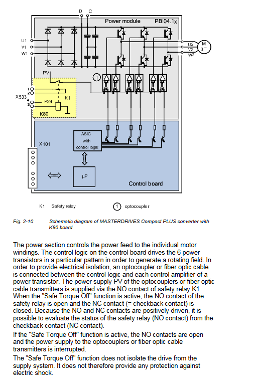
STO (Safe Torque Off) cuts off the motor torque output to prevent accidental starting EN 61800-5-2, Stop Category 0
SS1 (Safe Stop 1) time controlled deceleration cuts off torque, controllable shutdown EN 61800-5-2, Stop Category 1
Dual channel design for safety circuit, diagnostic coverage rate of 90%+EN ISO 13849-1:2008
3. Auxiliary functions
Automatic motor recognition (P115): supports static/dynamic recognition, automatically matches motor parameters
Fly start (P130): Smooth start when the motor rotates to avoid surge current
Kinetic Energy Buffer (KIB): Utilizing the kinetic energy of the motor to maintain the DC bus voltage during power outages
DC braking: quick stop, adjustable braking time (0-100s)
Temperature adaptive: Adjust the output according to the motor temperature to protect the motor
Parameterized operation
1. Comparison of parameterization methods
Parameterized tool operation method, core advantages, applicable scenarios
PMU (panel) local button operation, 4-digit 7-segment display without additional equipment, quick setup, simple debugging, troubleshooting
OP1S (operation panel) displays in Chinese/English, supports parameter upload and download, has strong portability, and supports multi slave site and multi device debugging
DriveMonitor (software) PC operation, graphical interface for batch configuration, script editing for complex system configuration, offline debugging
2. Key parameterization process
Factory reset: P053=6 → P060=2 → P970=0, restore default parameters
Quick parameterization (P060=3): Input motor nameplate data → Select control mode → Set command source → Automatic parameterization
Detailed parameterization: power segment definition → board configuration → motor parameters → control parameters → communication parameters → safety parameters
Parameter backup: OP1S or DriveMonitor upload parameter set, supports batch download
3. Core parameter group
Function description of key parameters in parameter group
Motor parameters P101 (rated voltage), P102 (rated current), P107 (rated frequency), P108 (rated speed) match the motor nameplate data
Control parameters P100 (control mode), P235 (speed loop gain), P240 (speed loop integration time) to adjust and control dynamic performance
Instruction parameters P443 (main given source), P554 (ON/OFF 1 source), P573 (MOP rise) define the control instruction source
Configure safety loop signals for safety parameters P651 (digital output source) and P698 (SCI digital output)
Communication interface
1. Detailed explanation of communication protocol
Protocol type, transmission rate, number of connections, core usage
USS 9.6-19.2kBd up to 32 slave stations with simple bus control and parameterization
PROFIBUS DP 9.6kBd-12MBd up to 126 slave industrial automation network integration
PROFINET IO 100MBd real-time communication high-precision synchronous control
SIMOLINK 100MBd with up to 200 nodes for multi axis synchronization and high-speed data transmission
CAN 1Mbps up to 31 nodes low-cost distributed control
2. Key points of communication configuration
Address setting: USS/PROFIBUS addresses 1-247 to avoid conflicts
Baud rate matching: All slave stations must have the same baud rate as the master station
Bus terminal: Terminal resistors (120 Ω) need to be connected at both ends of the PROFIBUS/CAN bus
Protocol selection: Choose based on real-time requirements, prioritize high-precision synchronization PROFINET/SIMOLINK
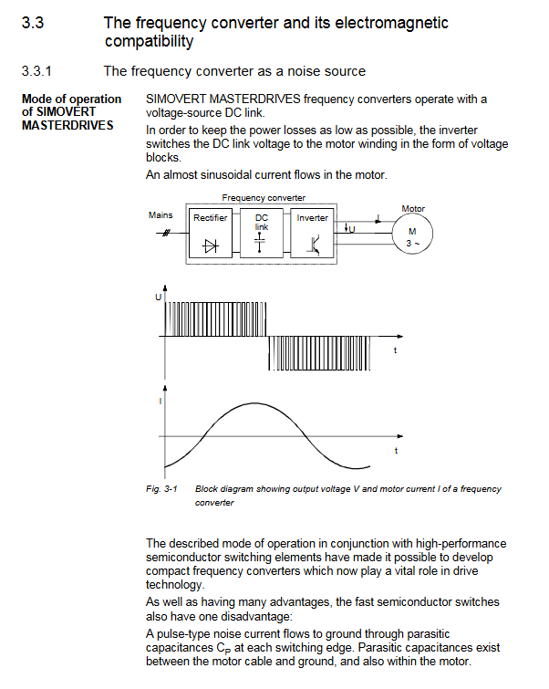
EMC Design Specification
1. Core EMC rules
Partition isolation: Install noise sources (inverters, braking units) and sensitive equipment (controllers, sensors) in different zones
Cable separation: The distance between power cables and signal cables should be ≥ 20cm, and cross wiring should be done vertically
Shielding treatment: The shielding layer of the motor cable/signal cable is grounded 360 ° without interruption
Grounding requirements: The grounding resistance of the cabinet should be ≤ 4 Ω, and all metal components should be reliably grounded
Filter configuration: Install EMC filter on the power side to reduce harmonic interference
2. Typical EMC configuration
Input side: EMC filter+incoming reactor to suppress conducted interference
Output side: dv/dt filter/sine filter, reducing motor cable radiation interference
Signal side: Use shielded twisted pair cables for analog signals, away from power cables
Safety and Compliance
1. Safety operation requirements
Qualification requirements: Only qualified personnel are allowed to operate, and familiarity with the safety manual is required
Power off operation: Before wiring/maintenance, disconnect all power sources and wait for the capacitor to discharge
Electromagnetic radiation: The device generates an electromagnetic field during operation, and pacemaker wearers should stay away from it
Environmental restrictions: It needs to be installed in a closed cabinet to avoid contact with high-temperature components
2. Compliance standards
International standards: IEC 61800-5-2 (safety), IEC 60947 (electrical safety) EN 55011(EMC)
Domestic standard: GB/T 12668 (Variable Speed Electrical Transmission System)
Certification qualifications: CE, UL, CSA, CCC
- YOKOGAWA
- Reliance
- ADVANCED
- SEW
- ProSoft
- WATLOW
- Kongsberg
- FANUC
- VSD
- DCS
- PLC
- man-machine
- Covid-19
- Energy and Gender
- Energy Access
- Renewable Integration
- Energy Subsidies
- Energy and Water
- Net zero emission
- Energy Security
- Critical Minerals
- A-B
- petroleum
- Mine scale
- Sewage treatment
- cement
- architecture
- Industrial information
- New energy
- Automobile market
- electricity
- Construction site
- HIMA
- ABB
- Rockwell
- Schneider Modicon
- Siemens
- xYCOM
- Yaskawa
- Woodward
- BOSCH Rexroth
- MOOG
- General Electric
- American NI
- Rolls-Royce
- CTI
- Honeywell
- EMERSON
- MAN
- GE
- TRICONEX
- Control Wave
- ALSTOM
- AMAT
- STUDER
- KONGSBERG
- MOTOROLA
- DANAHER MOTION
- Bentley
- Galil
- EATON
- MOLEX
- Triconex
- DEIF
- B&W
- ZYGO
- Aerotech
- DANFOSS
- KOLLMORGEN
- Beijer
- Endress+Hauser
- schneider
- Foxboro
- KB
- REXROTH
- YAMAHA
- Johnson
- Westinghouse
- WAGO
- TOSHIBA
- TEKTRONIX
- BENDER
- BMCM
- SMC
- HITACHI
- HIRSCHMANN
- XP POWER
- Baldor
- Meggitt
- SHINKAWA
- Other Brands
- UniOP
- KUKA
- IBA
- Beckhoff
-
LTI SC52.0040.0012.0000.0 - Servo Drive
-
Lti SC52.0040.0012.0000.0 - Servo Drive
-
Milton Industries LTI Tool By Milton LT1240 - 1/2" Drive Lugnut Remover
-
LTi Drives SO84.200.P030.0000.0-W - Servo Spindle Drive
-
LTI DRIVES LSP08-035-320-30-B0R1PY170 - Servo Motor
-
LTI DRIVES SE84.200.SC00.0001.0-W - Servo Drive
-
Lust CDE34.005.W2.2 - Lti Drives Controller
-
LTi SO84.012.0030.0011.2 - ServoOne Servo Drive
-
LTi Drives SO CM-P.0010.11.00.0 - Servo Drive Controller
-
LTi CDE34.017.W3.0 - Servo Drive
-
LTI Drives CDB32.004, C2.0,SH - Positioning Controller
-
LUST CM-CAN1 - LTi DRIVES Communication Module
-
LTi SO84.012.1030.0000.2 - Servo Drive
-
LTI MOOG CDE54.044 - PITCHMASTER FREQUENCY CONVERTER 181-01019
-
MOOG LTI 181-01019 CDE54.044 - PITCHMASTER FREQUENCY CONVERTER
-
Lust LTi Drives CDE34.010,D2.0 - Servo Drive Controller
-
LTI SO84.032.0003.0101.2 - Servo Drive
-
Seagate 9CC132-302 Harris LTI-CS IRT-34-0021-01 - Hard Drive 160GB
-
LTI SO84.032.0003.0001.2 - Servo Drive
-
LTI SO24.007.0070.0000.1 - SERVO CONTROLLER
-
LTi drive CDA32.003.C3.0.H05-01.PC1 - Servo Drive
-
LTI SO84.016.0030.0000.2 - SERVO CONTROLLER
-
LUST LTI CD A34.008,W1.4, BR - SERVO DRIVE
-
MOOG LTI 181-01019 CDE54.044 - PITCHMASTER FREQUENCY CONVERTER
-
LTI MOOG 181-01019 - PITCH Master Servo Drive CDE54.044
-
LTI SERVO ONE SO84.045.0030.0001.2-W - Drive
-
LUST LTi SO84.032.0040.0000.2 - SERVO ONE DRIVE
-
LTi Drives LSH-074-2-30-3 20/T1,G6.1M - SERVO MOTOR
-
LTI SO84.016.0000.0101.2 - servo drive
-
LTI SA54.0550.0033.0000.0 - Servo Drive
-
LTI SA54.0550.0033.0000.0 - Servo Drive
-
LTI LT 4850 - 3/8" Drive 3-Pc Twist Socket Transmission Drain Plug Removal System
-
LTI Tools LT4400-30 Lock Technology - 3/4" Twist Socket 1/2" Drive Lugnut Remover
-
LTI Tools LT-1400C - 1/2 Drive Wheel Torque Extension Tool
-
LTI Tools LT1250 - 1/2" Drive Dual Sided Socket Lug Nut Remover Tool
-
LTI SO84.032.0003.0101.2 - Servo Drive
-
LTI MOOG 181-01019 - PITCH Master Servo Drive CDE54.044
-
MOOG LTI 181-01019 CDE54.044 - PITCHMASTER FREQUENCY CONVERTER
-
MOOG LTI 181-01019 CDE54.044 - PITCHMASTER FREQUENCY CONVERTER
-
MOOG LTI 181-01019 CDE54.044 - PITCHMASTER FREQUENCY CONVERTER
-
LTI SA54.0550.0033.0000.0 - Servo Drive
-
LTI Tools LT-4800 - 7 Piece Twist Socket 3/8" Drive Oil Drain Plug Removal Set
-
LTI SA54.0550.0033.0000.0 - Servo Drive
-
LTI Drive SO24.007.00300000.0 - Servo Drive
-
LTI TOOLS LTI 1400-I - Drive Wheel Torque Extension
-
LTI Tools LT4400-3 - 3/4" 19mm Twist Socket 1/2" Drive Lugnut
-
LTI TOOLS LTI 1400-BB - Drive Wheel Torque Extension
-
LTI SO84.032.0003.0101.2 - Servo Drive
-
LTI Tools LT-4512 - 3/8" Drive 12mm Twist Socket
-
LTI MOTION Luster SO84.032.0003.0001.2 - Servo Drive
-
LTI Tool By Milton LT1600P - 1" Drive Torx Stick
-
LTI Lust VF1424L,HF,OP2,S56 - Variable Frequency Drive
-
LUST CDA32.004,C1.4,H08,B0 - SERVO DFRIVE CM-CAN1 Module
-
LTI SO84.045.0002.0001.2-W - Drive
-
LTI Lust VF1404M,C9,PT1,BR1 - Inverter Type VF1404M
-
LTI SA54.0550.0033.0000.0 - Servo Drive
-
LTI Tools LT-1400C - 1/2" Drive Wheel Torque Extension
-
Lust LTI DRiVES CDA32.006, C3.0, H09 - Variateur De Fr茅quence Frequency Inverter
-
LTI MOOG CDE54.044 - PITCH master SERVO DRIVE
-
LTI MOOG CDE54.044 - PITCH master SERVO DRIVE
-
LTI SO84.143.0020.0101.2-W - servo drive
-
LTI MOTION SC34.0200.0011.0000.0 - Servo drives
-
LTI SO84.032.0003.0001.2 - Servo Drive
-
LTI DRIVES GmbH MS100 - Assembly Set Mounting Kit
-
LTI SO84.032.0003.0001.2 - Servo Drive
-
LTI SO84.032.0003.0001.2 - Servo Drive
-
LTI MOTION SO84.032.0003.0101.2 - servo drive
-
LTI SO84.032.0003.0101.2 - Servo Drive
-
LTI MOOG CDE54.044 - PITCH master SERVO DRIVE
-
LTI MOTION CDE32.004.C2.4 - Servo drives
-
LTI CDD34.032锛學x.x锛孊R锛孭C1 - Servo Drive
-
Lust LTI DRiVES CDA32.006, C3.0, H09 - Inversor De Frecuencia Frequency Inverter
-
Lust SO84.008.0030.1000.0 - Servo One LTi Drive
-
LTI MOTION SO84.032.0003.0101.2 - Servo drives
-
LUST LTi CDA32.004,C1.4 - SERVO DRIVE
-
LTI MOOG CDE54.044 - PITCH Master SERVO DRIVE
-
LTI KEBA CDB32.004 C2.7, SH - PN: 08673530 Frequency Inverter
-
LTI Tools LT-1400C - 1/2" Drive Wheel Torque Extension
-
LTI LT1400-E - 1/2" Drive Wheel Torque Extension
-
LTI MOOG 181-01019 - PITCH master SERVO DRIVE CDE54.044
-
LTI LSN-097-0510-30-560/T1 - Actuator Motor
-
LTI Tools LT 4800 - 7 Piece 3/8" Drive Twist Socket Oil Drain Plug Removal System
-
LTI DRIVES GmbH MS100 - MONTAGESET Assembly Set Mounting Kit
-
Lti SC52.0040.0012.0000.0 - Servo Drive
-
LTI DRIVES GmbH MS100 - Juego De Montaje Assembly Set Mounting Kit
-
LTi DSM4-14.2-21R83-200 - Drives servomoteur Servo Motor
-
MOOG CDE 54.044.GDA - Pitch Master Industrielle Turbine Lti Drive
-
LTI SO24.004.0030.1000.0 - Servo Drive Controller
-
Lti MOOG CDE54.044 - Pitch Master Servo Drive
-
Lust LTI DRiVES CDA32.006, C3.0, H09 - Inverter
-
LTI MOTION GMBH CDB34.006,W3.0,PC1,H39 - Frequency inverter
-
LTI SO84.032.0003.0001.2 - Servo Drive
-
MOOG CDE 54.044.D - Pitch Master Industrielle Turbine Lti Drive
-
LTI TOOLS LT-1460 - 1/2" DRIVE WHEEL TORQUE EXTENSION KIT 5 PIECE SET
-
Lust Cdb32.003, C2.4 - Lti Drives Servoregulador Frecuencia Servo Controller Inverter
-
Lust LTI DRIVES CDA32.006, C3.0, H09 - Frequency Inverter
-
Lust Lti SO82.004.0030.0000.2 - Servo Drive
-
LTI MOTION SC34.0200.0011.0000.0-SL - Servo drives
-
LTI MOTION SA54.0075.0033.0000.0 - Servo drives
-
LTI MOTION SC32.0075.1011.0000.0 - Servo drives
-
LTI Servo-One Junior SO22.006.0080.1000.0 - Servo Controller Servoregler
-
LUST CDA32.004, C1.4, H08, B0 - Servo Drive & LTI CM-CAN1 Module
-
LTI DRIVES LSP08-035-320-30-B0R1PY170 - Servo Motor
-
LUST LTI CDA32.004,C1.4.H08.B0 - SERVO CONTROLLER DRIVES
-
LUST LTi DRiVES CDS44.072LC1.2 - Servo Drive
-
Lti Servo-One Junior SO22.006.0082.1000.0 - Servo Controller Servoregler
-
LUST CDA32.008,C2.0,HF - Lti DRIVES Spindle Drive Inverter
-
LTI SO22.003.0082.0000.0 - Servo Drives One junior Servo Controller Servoregler
-
Lust Lti Drives CM-CAN1 - Communication Module
-
LUST Lti Drives Vf1202s, G8, I6 - Frequency Inverter Drive
-
LTI DRIVES BR-090.03.540.UR.H38 - Bremswiderstand Brake Resistor
-
LTi DRIVES PM-E40.2DRA054P - Wind Turbine Pitch Control Inverter
-
LTi Drives GmbH br-110.01.540-UR - Brake Resistor
-
LTI Drives LSN-097-0960-30-0560/T1,S4,B - Servo Motor
-
LUST CDA34.006.C2.0 - LTI Drives Servoregler
-
LUST LTI DRIVES SERVO ONE JUNIOR SO24.002.0020.0000.1 - Servo Drive Controller
-
LTI MOTION SO84.032.0003.0001.2 - Servo drives
-
LTI DDTD750V2-120 - IBOP ACTUATOR CYLINDER FOR TOP DRIVE
-
LTI CDE32.004, C2.4 - SERVO DRIVE
-
LUST LTI DRIVES CDD34.017 W3.4PC1 - Servo Drive Controller
-
LTI CDA3208,C3,0,HF - AC SERVO DRIVE
-
LUST LTI DRIVES LSH-074-3-30-560/T1,G6.1S - SERVO MOTOR
-
LUST Lti CDB32.004.C2.4.SH - AC Servo Drive
-
LTi CDA32.006, C3.0, H09 - Servo Drive
-
LTI SO22.003.0010.0000.0 - Servo Drive Servo one junior Servoregler Controller
-
LTi Drives DSM4-14.2-21R83-200 - Servo Motor
-
LUST Lti Drives Lsh-097-1-30-560/T1, 1R - Servomotor
-
LTI 1237 - 7 Piece 1/2" Drive Flip Socket Set

K-JIANG

Add: Jimei North Road, Jimei District, Xiamen, Fujian, China
Tell:+86-15305925923