
K-WANG


Siemens SINAMICS DCM DC Converter and Control Module
Electronic module: Integrated control unit (CUD) with reserved rotatable bracket slots, supporting additional CUD expansion to enhance control flexibility and redundancy.
Power section: A fully controlled three-phase bridge circuit is constructed using thyristors, which are divided into two driving types - two quadrant driving (B6C structure) and four quadrant driving ((B6) A (B6) C structure), to meet the speed and braking requirements under different operating conditions.
Cooling system: Equipment with a rated DC current ≤ 125A adopts a self ventilated design, while equipment with a rated DC current ≥ 210A is equipped with an integrated fan for forced air cooling to ensure stable operation of power components.
Excitation power section: Standard single quadrant excitation power unit (including freewheeling circuit), optional non excitation version or two quadrant excitation version (suitable for high dynamic excitation current change scenarios), and integrated excitation overvoltage protection function.
Power supply and operation unit: including electronic device power supply; Standard BOP20 operation panel, AOP30 advanced operation panel requires additional purchase.
Siemens SINAMICS DCM DC Converter and Control Module
Core components of the product
The SINAMICS DC MASTER series DC converter consists of multiple key functional modules, which work together to achieve DC drive control. The specific components and functions are as follows:
Electronic module: Integrated control unit (CUD) with reserved rotatable bracket slots, supporting additional CUD expansion to enhance control flexibility and redundancy.
Power section: A fully controlled three-phase bridge circuit is constructed using thyristors, which are divided into two driving types - two quadrant driving (B6C structure) and four quadrant driving ((B6) A (B6) C structure), to meet the speed and braking requirements under different operating conditions.
Cooling system: Equipment with a rated DC current ≤ 125A adopts a self ventilated design, while equipment with a rated DC current ≥ 210A is equipped with an integrated fan for forced air cooling to ensure stable operation of power components.
Excitation power section: Standard single quadrant excitation power unit (including freewheeling circuit), optional non excitation version or two quadrant excitation version (suitable for high dynamic excitation current change scenarios), and integrated excitation overvoltage protection function.
Power supply and operation unit: including electronic device power supply; Standard BOP20 operation panel, AOP30 advanced operation panel requires additional purchase.
General Technical Specifications
1. Standard compliance
The product complies with multiple international and industry standards to ensure electrical safety, electromagnetic compatibility, and operational reliability. The core standards are listed in the table below:
Standard Number, Standard Name, and Scope of Application
EN 50178/IEC 62103 Electronic Equipment Standard for Power Facilities
EN 50274 Low voltage switchgear and control equipment components: Protection against electric shock (preventing accidental direct contact with hazardous live parts)
EN 60146-1-1 Semiconductor converters: General requirements and specifications for grid commutated converters
EN 61800-1 Adjustable Speed Electric Drive Systems Part 1: (DC Drive) General Requirements and Rating Specification for Low Voltage Adjustable Speed DC Drive Systems
EN 61800-3 Adjustable Speed Electric Drive Systems Part 3: Electromagnetic Compatibility (EMC) Product Standard with Specific Test Methods
EN 61800-5-1 Adjustable Speed Electric Drive Systems Part 5-1: Safety Requirements (Electrical, Thermal, and Energy Related)
UL 508 C Power Conversion Equipment UL Standard (575V and below equipment certified, UL file number E203250)
2. Electrical safety and performance
Overvoltage level and strength: The overvoltage level of the power supply circuit is EN 61800-5-1 Class II, which is Class III relative to the environment (other power supply circuits, enclosures, electronic devices); The overvoltage strength meets the EN 50178 Class 1 standard.
Short circuit current: Different combinations of supply voltage and rated DC current correspond to different maximum short-circuit currents. For example, in a 400/480V three-phase AC power supply, the maximum short-circuit current for equipment with a rated DC current of 15-1200A is 65kA, and for equipment with a rated DC current of 3000A, it can reach 100kA.
Radio interference suppression: The radio interference suppression function that complies with the EN 61800-3 standard is not configured. Additional accessories need to be purchased to meet the relevant requirements.
3. Stability of closed-loop control
Based on the thermal operation status of the equipment (rated motor speed), under specific premise conditions (ambient temperature ± 10 ℃, supply voltage ± 10%/-5%, temperature coefficient of the speed measuring generator with temperature compensation 0.15 ‰/10 ℃, constant given value), the control accuracy is as follows:
Pulse encoder operation+digital setpoint: speed deviation ∆ n=0.1% rated motor speed
Simulated speedometer+simulated setpoint: speed deviation ∆ n=0.006% rated motor speed
4. Environmental and mechanical parameters
Specific requirements for parameter categories
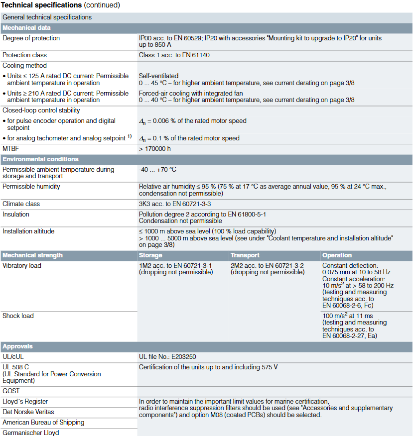
Basic protection level IP00 (EN 60529); Devices with ≤ 850A can be upgraded to IP20 through the "IP20 Upgrade Installation Kit"; Electrical safety level EN 61140 Class 1
Temperature range operation: ≤ 125A equipment 0-45 ℃, ≥ 210A equipment 0-40 ℃ (high temperature requires capacity reduction); Storage/transportation: -40-70 ℃
Relative humidity ≤ 95% (at 24 ℃), annual average ≤ 75% (at 17 ℃), condensation is strictly prohibited
Climate grade EN 60721-3-3 3K3
Insulation pollution level EN 61800-5-1 Class 2, condensation is strictly prohibited
Installation height ≤ 1000m altitude (100% load capacity); 1000-5000m altitude needs to refer to the derating specifications
Mechanical strength vibration: storage of 1M2 (EN 60721-3-1), transportation of 2M2 (EN 60721-3-2), constant deflection of 0.075mm during operation at 10-58Hz/constant acceleration of 10m/s ² during 58-200Hz; Impact: 100m/s ² (11ms, EN 60068-2-27 Ea) during operation
Mean Time Between Failures (MTBF)>170000 hours
5. Certification qualifications
In addition to UL/cUL certification, the product also complies with GOST standards and has been certified by Lloyd's Register, Det Norske Veritas, American Bureau of Shipping, and Germanischer Lloyd (ship certification requires radio interference suppression filters and M08 option - coated PCB).
Typical model technical parameters (taking 480V three-phase AC and four quadrant operation as an example)
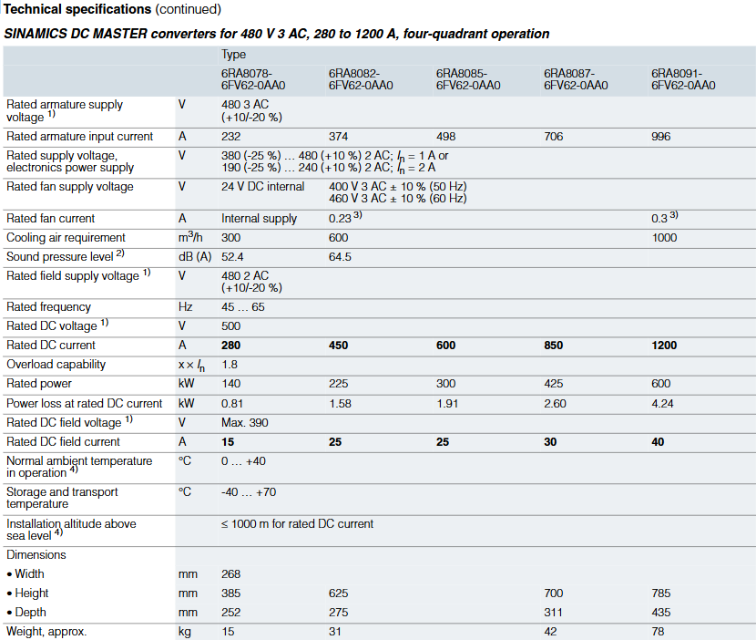
For the series models with rated armature supply voltage of 480V three-phase AC (± 10%/-20%) and four quadrant operation, the core parameters are shown in the following table (some key models):
Model Rated armature input current (A) Rated DC voltage (V) Rated DC current (A) Rated power (kW) Rated excitation voltage (V) Rated excitation current (A) Cooling air demand (m ³/h) Sound pressure level (dB (A)) Size (W × H × D, mm) Weight (kg)
6RA8078-6FV62-0AA0 232 500 280 140 480 two-phase AC 15 300 52.4 268 × 385 × 252 15
6RA8082-6FV62-0AA0 374 500 450 225 480 two-phase AC 25-268 × 625 × 275 31
6RA8085-6FV62-0AA0 498 500 600 300 480 two-phase AC 25 600-268 × 700 × 311 42
6RA8087-6FV62-0AA0 706 500 850 425 480 two-phase AC 30 1000 64.5 268 × 785 × 435 78
6RA8091-6FV62-0AA0 996 500 1200 600 480 two-phase AC 40-268 × 785 × 435-
Note: The armature/excitation supply voltage can be set to be lower than the rated value through parameter settings. The minimum input voltage for 400/480/575V rated voltage equipment is 50V, and for higher rated voltage equipment it is 85V. When the supply voltage undervoltage is ≤ 5%, the rated DC output voltage can be maintained.
Selection and ordering data
1. Core dimensions for selection
Selection should be based on armature circuit parameters (supply voltage, rated DC voltage/current), excitation circuit parameters (supply voltage, rated DC current), rated power, matched with corresponding models and matching fuses. Different supply voltages (400V/480V/575V/690V/830V/950V three-phase AC) correspond to different model sequences, for example:
400V three-phase AC: 6RA80xx-6DV62-0AA0 series
480V three-phase AC: 6RA80xx-6FV62-0AA0 series
575/690V three-phase AC: 6RA80xx-6GV62-0AA0 series
2. Rules for matching fuses
Different models require specific types and specifications of armature/excitation circuit fuses, such as:
6RA8013-6FV62-0AA0 (480V three-phase AC, 15A rated DC current): armature fuse 3NE1814-0 (2 pieces), excitation fuse 5SD420
6RA8087-6FV62-0AA0 (480V three-phase AC, 850A rated DC current): armature fuse 3NE3338-8+3NE3334-0B (parallel), excitation fuse 5SD480
High current models (such as 6RA8091-6FV62-0AA01200A rated DC current): Built in armature fuse, no external semiconductor fuse required, excitation fuse 3NE1802-0 (UL certified)
- YOKOGAWA
- Reliance
- ADVANCED
- SEW
- ProSoft
- WATLOW
- Kongsberg
- FANUC
- VSD
- DCS
- PLC
- man-machine
- Covid-19
- Energy and Gender
- Energy Access
- Renewable Integration
- Energy Subsidies
- Energy and Water
- Net zero emission
- Energy Security
- Critical Minerals
- A-B
- petroleum
- Mine scale
- Sewage treatment
- cement
- architecture
- Industrial information
- New energy
- Automobile market
- electricity
- Construction site
- HIMA
- ABB
- Rockwell
- Schneider Modicon
- Siemens
- xYCOM
- Yaskawa
- Woodward
- BOSCH Rexroth
- MOOG
- General Electric
- American NI
- Rolls-Royce
- CTI
- Honeywell
- EMERSON
- MAN
- GE
- TRICONEX
- Control Wave
- ALSTOM
- AMAT
- STUDER
- KONGSBERG
- MOTOROLA
- DANAHER MOTION
- Bentley
- Galil
- EATON
- MOLEX
- Triconex
- DEIF
- B&W
- ZYGO
- Aerotech
- DANFOSS
- KOLLMORGEN
- Beijer
- Endress+Hauser
- schneider
- Foxboro
- KB
- REXROTH
- YAMAHA
- Johnson
- Westinghouse
- WAGO
- TOSHIBA
- TEKTRONIX
- BENDER
- BMCM
- SMC
- HITACHI
- HIRSCHMANN
- XP POWER
- Baldor
- Meggitt
- SHINKAWA
- Other Brands
- UniOP
- KUKA
- IBA
- Beckhoff
- ADLINK
-
ADLINK HPCI-14S12U - Industrial Control Backplane 12PCI Backplane PCI-14S Passive Backplane
-
ADLINK PCIe-GIE74C - image acquisition card 4-CH GigE Vision PoE+ Frame Grabber
-
ADLINK PCI-8164 - control card 4-Axis Advanced Motion Controller Board
-
ADLINK PCIe-U304 - 4 Port USB3 PCIe Frame Grabbers USB Screw Hole Card
-
ADLINK PCI-9112 - Multi-Function Data Acquisition Card DAQ Card
-
ADLINK PCI-7432 - 51-12013-0A50 4-CH Isolated Numérique I/O PCI Cartes Digital I/O Card
-
ADLINK PCA-6106P3-0C1 REV.C1 - backplane 6-Slot Passive Backplane Board
-
ADLINK PCI-7224 - 24-CH Opto-Isolated Digital I/O PCI Board
-
ADLINK CPCI-7433R(G) - Digital Input Board Rear I/O CompactPCI Card
-
ADLINK EBP-13E4 - 51-46703-0A30 Industrial PC Backplane Passive Backplane
-
ADLINK PCIE-HDV62 - Image acquisition card High Definition Video Frame Grabber
-
ADLINK EBP-13E4 - 51-46703-0A30 Industrial Backplane Board Passive Backplane
-
ADLINK 90111-B1 / CPCI-6770 - PCB CPU MODULE CompactPCI Single Board Computer
-
ADLINK PCI-7248 - DATA ACQUISITION PCI CARD 48-CH Parallel Digital I/O Board
-
ADLINK PCI-7230 - 51-12003-0a50 board PCI7230 32-CH Isolated Digital I/O Card
-
ADLINK PCI2A000CB - 51-20000-0B30 Multi-Function DAQ Card Baseboard
-
ADLINK PCI-8134-005 - 4-Axis Motion Controller Card
-
ADLINK PCI-7224 - 24-CH Opto-Isolated Digital I/O PCI Card
-
ADLINK PCI-7434 - 64-CH Isolated Digital Output Card
-
ADLINK PCI-8132 - motion control card 2-Axis Servo & Stepper Controller
-
ADLINK PCI-8134 - Motion Controller PCI Card 4-Axis Controller Board
-
ADLINK PCI-8164 - Motion Control Card 51-12406-0A40 4-Axis Controller
-
ADLINK 51-12001-0C20 - Circuit Board Data Acquisition Interface Module Hardware
-
ADLINK NuPR0-840 - industrial control motherboard Full-Size PICMG CPU Board
-
ADLINK PCI-7444 - 51-12023-0A10 card 128-CH Isolated Digital Output Board
-
ADLINK PCI-1612B - data acquisition card 4-Port RS-232/422/485 Serial Communication Card
-
ADLINK PCI-6208V 009 - 8/16-CH 16-Bit Analog Output Cards PCB-I-E-482=6BX3
-
ADLINK NUPRO-935A/LV - industrial control motherboard Full-Size PICMG SBC Board
-
ADLINK PCI-9114DG - Multi-Function DAQ Card Data Acquisition PCI Card
-
ADLINK ACL-7130 - Data acquisition card Isolated Digital I/O Board
-
ADLINK ABX-6300D-4E1-BP - board ABX6300D4E1BP Video Interface Expansion Card
-
ADLINK CPCI-6940 - CPCI-6940/D1539/M16-0(EA)-000E 6U CompactPCI Processor Board
-
ADLINK NuPRO-760 - industrial control motherboard Half-Size PICMG SBC CPU Board
-
ADLINK IMB-M42H (G)-0020 - industrial control motherboard LGA1155 Micro-ATX Mainboard
-
ADLINK RTV-24 / PCI-MP4S - 51-12519-1C30 4-Channel Real Time Video Capture Board
-
ADLINK PCI-8134 - 4-Axis Servo & Stepper Motion Controller Card
-
ADLINK MXC-6101D - V.PC000.002.ST.00 Box PC Configurable Embedded Computer
-
ADLINK PCI-8134A - 51-12421-0A10 Motion Control Card 4-Axis Controller Card
-
ADLINK DIN-100S / DIN-100SA1 - Technology SCSI-II TB 100-PIN Terminal Block Board
-
ADLINK DIN-812M001 / DIN812M001 - 51-14034-0A1 51140340A1 Terminal Module Breakout Interface
-
ADLINK PCI-8164 - Servo motion control 4-Axis Advanced Controller Card
-
ADLINK PCIe-GIE64 - Acquisition card GigE Vision PoE+ Frame Grabber
-
ADLINK M-302 - Industrial control motherboard ATX PC Board Mainboard
-
ADLINK PCI-8134 - Motion Controller PCI Card 4-Axis Controller Board
-
ADLINK PCI-RTV24 - Image capture card Analog Video Frame Grabber
-
ADLINK PCI-8102 - Motion control card 2-Axis Servo & Stepper Controller Board
-
ADLINK PCI-9112 REV.B1 - Card Multi-Function Data Acquisition Card
-
ADLINK HSI-DI32-M-N / HSL-TB32-M-DIN - Discrete I/O MODULE Distributed Automation Module System
-
ADLINK PCI-7296 - IO card REV.A3 96-CH Parallel Digital I/O Card
-
ADLINK DIN-814P-A4 / 814Y - terminal board Motion Control Interface Block
-
ADLINK DIN-814P-A4 - 51-14056-0A10 PCB-I-E-2736=ZA01 Screw Terminal Board Breakout
-
ADLINK M-322 - motherboard Industrial Control Computer Mainboard
-
ADLINK NUPRO-406 REV:B1 - industrial control motherboard Full-Size PICMG CPU Board
-
ADLINK AMP-204C - card DSP-Based 4-Axis Advanced Pulse-Train Controller
-
ADLINK HPCI14S REV.B1 - industrial computer baseboard 14-Slot Passive Backplane
-
ADLINK PCI-7250 - 8-CH Relay Output & 8-CH Isolated DI PCI Card
-
ADLINK EBP-13E2 - baseplate Passive Backplane Industrial Computer Chassis Board
-
ADLINK LPCI-3488A - PCI-GPIB card 51-12801-0A30 acquisition card IEEE-488 Interface Board
-
ADLINK PCI-6216V-GL - 51-12201-0C30 16-CH 16-Bit Voltage Analog Output Card
-
ADLINK ACL-8454 - 16-CH Isolated Digital I/O & 4-CH Counter Card
-
ADLINK HPCI-9S7U - backplane Passive Backplane Compatible with NuPRO-A301 852 841 842
-
ADLINK DAQ-2010-007 - Simultaneous-Sampling Multi-Function Data Acquisition Card
-
ADLINK MP-C154 - 51-64205-0A10 Motion Control Card 4-Axis Controller Board
-
ADLINK MXE-202/mSSD16B/WiFi-BT - Matrix Rugged I/O Platform Embedded Fanless Computer
-
ADLINK CM-920-R-17 - PC/104-Plus Single Board Computer Module Intel Celeron M
-
ADLINK PCI-7250 NSMP - 8-CH Relay Output & 8-CH Isolated DI Card
-
ADLINK PCI-8164 - 4-Axis Motion Controller PCI Card W/ Cable and Breakout Box
-
ADLINK EMX-100 - Ethernet-based 4-axis Motion Controllers Distributed Motion Module
-
ADLINK PCI-8134A - Press control card 4-Axis Motion Controller Board
-
ADLINK M-845EG REV:3.2 - industrial motherboard Pentium 4 Socket 478 Micro-ATX
-
ADLINK PCI-9114A Rev A2 DG - card High-Resolution Multi-Function Data Acquisition Board
-
ADLINK IEC-915GV - REV 1.1 Industrial motherboard Socket 478 CPU Board
-
ADLINK PCI-9111DG(G) - Data Acquisition Card Multi-Function DAQ Card
-
ADLINK HPCI-15S10 REV:B2 - Industrial computer base plate Passive Backplane Board
-
ADLINK NuPR0-840 / NuPR0-840DV - industrial control motherboard Full-size PICMG CPU Board
-
ADLINK RTV-24 / PCI-MP4S - 51-12519-1C30 4-Channel Real Time Video Capture Board
-
ADLINK NUPRO-780 - industrial control motherboard Pentium III Single Board Computer
-
ADLINK PCI-7296 - 0050 card 96-CH Opto-Isolated Parallel DIO Card Set
-
ADLINK NUPRO-780 - industrial control motherboard PICMG Full-Size SBC
-
ADLINK PCI-7248 - 51-12006-0A3 002 Pci 7248 48-CH Parallel Digital I/O Card
-
ADLINK PCI-7230 - 32-CH Isolated Digital I/O Card
-
ADLINK AMP-204C - motion control card 4-Axis Advanced Controller Board
-
ADLINK PCI-1714UL - Card Ultra High-Speed 4-CH Simultaneous Sampling DAQ
-
ADLINK NuPRO-E330 - industrial computer equipment motherboard PICMG 1.3 SHB SBC
-
ADLINK AMP-204C - DSP-Based 4-Axis Advanced Pulse-Train Motion Controller Module
-
ADLINK PCI-7256 - 001 51-12206-0A2 REV.A2 LPCI-7256 16-CH Latching Relay Output Card
-
ADLINK ND6050 - NUDAM DIGITAL I/0 MODULE Distributed I/O Unit
-
ASEM BM100 - Box PC Embedded Fanless Industrial Computer
-
ADLINK PCI-7250 - PCI Acquisition Card 8-CH Relay Output & Isolated DI Board
-
ADLINK PCI-8164 - Servo motion control 4-Axis Controller Card
-
ADLINK NuPRO-A40H - Industrial Motherboard 51-41807-1A30 OSP LGA1155 H61
-
ADLINK ADMAX X300 SERVER - 51066010-0A30 motherboard Multi-Processor Mainboard
-
ADLINK CMe-GIE62+ - 51-32903-0A30 control card PC/104-Plus GigE Vision Frame Grabber
-
ADLINK NUPRO-780 - industrial control motherboard Full-Size PICMG SBC CPU Board
-
ADLINK ETX-AT-N270-18/GKTEL - 51-71111-OB10 motherboard ETX CPU Module Board
-
ADLINK DIN-812M - interface module Terminal Block Connection Board
-
ADLINK IMB-M42H - industrial control motherboard LGA1155 Micro-ATX Mainboard
-
ADLINK PXIS-2508 - 8-slot 3U PXI Instrument Chassis Power Hardware Assembly
-
ADLINK AMP-208C - Motion Control card DSP-Based 8-Axis Pulse-Train Controller
-
ADLINK PCI-9111 / PCI-9111DG - Multi-Function Data Acquisition Card DAQ Board
-
ADLINK IEEE-488 GPIB card - Bus Interface Controller Communication Board
-
ADLINK RTV-24 - 51-12519-1C30 image acquisition card Video Frame Grabber Card
-
ADLINK TB-24P/24-01 - Board 24 Way Screw Terminal Breakout Board
-
ADLINK HSL-DI16DO16-DB-NN - 51-23015-0A40 Distributed Discrete I/O Module Set
-
ADLINK PCI-7442 - switch quantity card data acquisition card 64-CH Isolated Card
-
ADLINK ACL-7130 REV. B2 - industrial control capture card Isolated Digital I/O PCI Card
-
ADLINK PCI-6S / PCI6S - Backplane 6-Slot Passive Backplane Chassis Board
-
ADLINK ACL-8113A - card Isolated Digital Input Card
-
ADLINK CPCI-6208V-003 - board cPCI CompactPCI 8-CH Analog Output Card
-
ADLINK DIN-100S-01(G) - SCSI 100-Pin Terminal Block Interface Board
-
ADLINK PCI-7433 - Isolated Digital Input Card 64-CH
-
ADLINK PCI-9812 - Synchronous sampling analog input card High-Speed DAQ Board
-
ADLINK PCI-7434 REV.B1 - PLOTECH PCB-I-E-1182=6EX2 64-CH Isolated Digital Output Card
-
ADLINK PCIe-RTV24 - 51-18016-0A20 4-CH Real-Time Video Capture Card PCIe Frame Grabber
-
ADLINK PCI-8144 / PCI-8144N - Motion control card 4-Axis Stepper Motor Controller
-
ADLINK DIN-68S-01 - terminal board 68-Pin Connector Terminal Block
-
ADLINK MP-C154 - Motion control card 4-Axis Advanced Controller Card
-
ADLINK PCI-7248 (G) - Motherboard 48-CH Parallel Digital I/O Card
-
ADLINK MXE-1301(G) - Intel Atom D2550+NM10 MXE 1300 Series 93-4130-0030 Embedded Computer
-
ADLINK PRO-841 Rev 2.0 / PRO-060907000670 - CPU 2.26GHz & RAM Industrial PC Board
-
ADLINK NuPRO-E330 - Industrial Motherboard System Host Board PICMG 1.3 SHB
-
ADLINK EBP-13E2 - Passive Backplane Industrial Chassis Baseboard
-
ADLINK PCI-8154 - 4-axis Motion Control Card Servo & Stepper Controller Board
-
ADLINK NuPrO-596 REV.B1 - industrial control motherboard Half-size PICMG CPU Board
-
ADLINK PCI-7852 / PCI-7851 - PLOTECH High-Speed Link Control Card Interface Board
-
ADLINK PCI-9112 - 51-12252-0D20 data acquisition card Multi-Function DAQ
-
ADLINK PCI-9112 - Circuit Board 51-12252-0C20 Multi-Function Data Acquisition Card
-
ADLINK NUPRO-761 REV:1.1 - industrial control motherboard PICMG Full-Size CPU Board

K-JIANG

Add: Jimei North Road, Jimei District, Xiamen, Fujian, China
Tell:+86-15305925923