
K-WANG


Honeywell SK Relay Installation and Maintenance
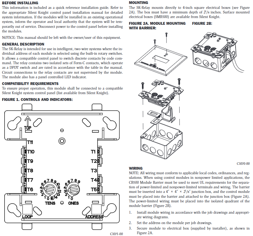
Structure: Contains two sets of isolated Form-C contacts, used as DPDT switches, with rated values in accordance with the table in the manual; The module does not monitor the circuit connections of relay contacts; The module also has an LED indicator controlled by a panel.
Honeywell SK Relay Installation and Maintenance
Product specifications
Normal operating voltage: 15 to 32 VDC
Maximum current consumption: 6.5 mA (when LED lights up)
Average working current: directly polling 230 μ A; Group polling 255 μ A
Terminal Resistance (EOL): Not used
Temperature range: 32 ° F to 120 ° F (0 ° C to 49 ° C)
Humidity: 10% to 93%, non condensing
Size: 4.5 inches high x 4 inches wide x 1.25 inches deep (can be installed on a box measuring 4 inches square and 2.125 inches deep)
Accessories: SMB500 Electrical Box
Product overview
Purpose: Suitable for intelligent two-wire systems, each module's independent address can be selected through a built-in rotary switch, allowing compatible control panels to switch discrete contacts through code commands.
Structure: Contains two sets of isolated Form-C contacts, used as DPDT switches, with rated values in accordance with the table in the manual; The module does not monitor the circuit connections of relay contacts; The module also has an LED indicator controlled by a panel.
Compatibility requirements
Need to connect to a compatible Silent Knight system control panel (specific list can be obtained from Silent Knight).
Preparation before installation
This information is only for a quick reference installation guide. For detailed system information, please refer to the corresponding Silent Knight control panel installation manual.
To install modules in existing operating systems, operators and local authorities need to be notified that the system will be temporarily suspended.
Disconnect the power supply of the control panel before installing the module.
This manual should be left to the owner/user of this device.
Installation method
SK Relay is directly installed on a 4-inch square electrical box (see Figure 2A), and the minimum depth of the box must be 2 inches.
Silent Knight provides surface mounted electrical boxes (SMB500).
Wiring requirements
All wiring must comply with applicable local codes, regulations, and laws.
When using control modules in non power limiting applications, CB500 module barriers must be used to meet UL's requirements for power limiting and non power limiting terminal and wiring separation. The barrier must be inserted into a junction box, and the control module must be placed in the barrier and connected to the junction box (Figure 2A). The power limiting wiring must be placed in the isolation quadrant of the module barrier (Figure 2B).
Install module wiring according to the engineering drawings and corresponding wiring diagrams.
Set the address on the module according to the engineering drawing.
Fix the module to the electrical box as shown in Figure 2A (provided by the installer).

Warning message
All relay switch contacts are in standby state (open) at the factory, but may have been switched to active state (closed) during transportation. To ensure that the switch contacts are in the correct state, the module must communicate with the panel before connecting the circuit controlled by the module.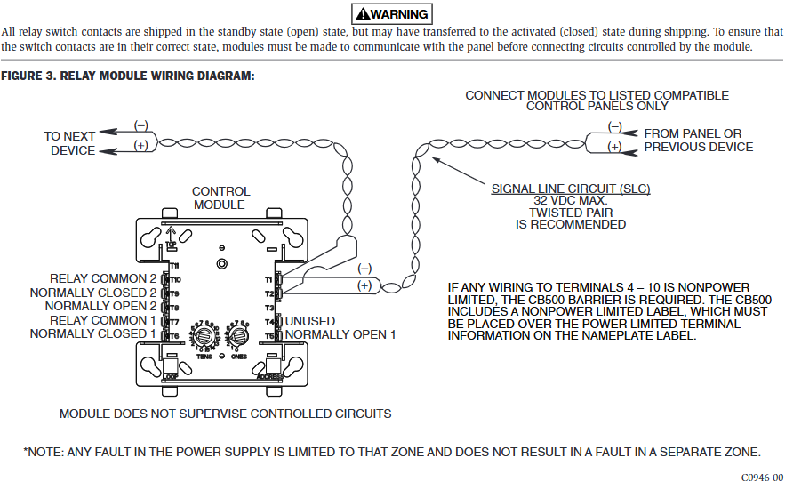
- YOKOGAWA
- Reliance
- ADVANCED
- SEW
- ProSoft
- WATLOW
- Kongsberg
- FANUC
- VSD
- DCS
- PLC
- man-machine
- Covid-19
- Energy and Gender
- Energy Access
- Renewable Integration
- Energy Subsidies
- Energy and Water
- Net zero emission
- Energy Security
- Critical Minerals
- A-B
- petroleum
- Mine scale
- Sewage treatment
- cement
- architecture
- Industrial information
- New energy
- Automobile market
- electricity
- Construction site
- HIMA
- ABB
- Rockwell
- Schneider Modicon
- Siemens
- xYCOM
- Yaskawa
- Woodward
- BOSCH Rexroth
- MOOG
- General Electric
- American NI
- Rolls-Royce
- CTI
- Honeywell
- EMERSON
- MAN
- GE
- TRICONEX
- Control Wave
- ALSTOM
- AMAT
- STUDER
- KONGSBERG
- MOTOROLA
- DANAHER MOTION
- Bentley
- Galil
- EATON
- MOLEX
- Triconex
- DEIF
- B&W
- ZYGO
- Aerotech
- DANFOSS
- KOLLMORGEN
- Beijer
- Endress+Hauser
- schneider
- Foxboro
- KB
- REXROTH
- YAMAHA
- Johnson
- Westinghouse
- WAGO
- TOSHIBA
- TEKTRONIX
- BENDER
- BMCM
- SMC
- HITACHI
- HIRSCHMANN
- XP POWER
- Baldor
- Meggitt
- SHINKAWA
- Other Brands
- UniOP
- KUKA
- IBA
- Beckhoff
- ADLINK
-
Beckhoff CX5020-0112 - PLC Module
-
Beckhoff CP2912-0000 - Control Panel
-
Beckhoff C6920-1047-0030 - industrial control cabinet control PC
-
BECKHOFF CX1020-0121 - CPU Module Power Supply Setup
-
Beckhoff EL6752 - DeviceNet Master EtherCAT Terminal
-
Beckhoff IP1002-B518 - Fieldbus Box Module
-
Beckhoff CP6606-0001-0020 - 7 inch Economy Panel PC incl. Connection Cable
-
Beckhoff CX5010-0111 - Controller Module
-
BECKHOFF AX2020-S62000-520 - SERVO DRIVE 5.76
-
Beckhoff EL1904 - 4-Channel Digital Input Module
-
BECKHOFF AX5201-0000 - Servo Drive
-
Beckhoff CP7201-1000-0000 - Industrial PC with Touch Screen
-
Beckhoff BK7350 - module Bus Coupler
-
BECKHOFF C6930-0010 - PLC PC Industrial PC
-
Beckhoff AX5125-0000 - Servo Amplifier
-
Beckhoff CX2100-0914 - Power Supply for External UPS for CX20xx
-
Beckhoff CP6608-1000-0010 - Control Panel
-
Beckhoff EL7221-9014 - EtherCAT Terminal, 1 Channel Motion Interface, 48 V DC
-
BECKHOFF CP2919-0000 - Multitouch Built-In Control Panel 24VDC 19"
-
BECKHOFF C6015-0010 - TWINCAT2 Single Core 1.46GHz Industrial PC
-
Beckhoff CU8803-0000 - Controller Module Transmitter
-
BECKHOFF CU1521-0000 - EtherCAT media converter
-
Beckhoff CX5140-0111 - Control Embedded PC HW 3.1 + Flash Card CX2900-0028 4GB
-
Beckhoff AX2513-B200 - Servo Amplifier Servodrive
-
Rexroth MSK061C-0600-NN-M1-UP1-NNNN - Engine Servo Motor
-
Beckhoff AM3031-0C01-0000 - Servo Motor
-
BECKHOFF CP7201-1000-0000 - Industrial PC with touch screen
-
BECKHOFF C6925-0000 - PLC Module Industrial PC
-
BECKHOFF EL5151-0021 - PLC module Encoder Interface
-
Beckhoff CX5130-0125-1001 - Module Embedded PC
-
BECKHOFF EP3356-0022 - EtherCAT Box Module
-
BECKHOFF AX5203-0000 - SERVO DRIVE
-
B&R X20IF1082 - COMMUNICATION INTERFACE MODULE POWER LINK
-
BECKHOFF EL7342 - PLC Module 2-Channel DC Motor Output
-
BECKHOFF CX8190 - Ethernet Controller
-
BECKHOFF CX2020-0120/4GB - CPU CX2100-0904 3x EL6900 EL1904 16GB RAM
-
Beckhoff CX5130-0112 - Module Embedded PC
-
Beckhoff CP7701-0001-0020 - Panel-PC Touch Panel 12" ELO Accutouch AMD ALX 500MHz
-
BECKHOFF CX5020-0111 - Embedded PC Controller
-
Beckhoff CX2040-0100 - Embedded PC HW: 4.0 + CX2100 0014 + 4GB CFast Card
-
Beckhoff CP6512-0001 0030 - Control Panel
-
beckhoff CX9020-0111-0900 - Controller Modules
-
Beckhoff IE3112 - Module Fieldbus Box
-
BECKHOFF CX8051 - PLC Module
-
BECKHOFF CX1100-0920 - module Power Supply
-
Beckhoff CP7921-1075-0000 - Control Panel
-
B&R 3NC352.6 - PLC Module
-
Beckhoff CX8095 - module Controller
-
beckhoff CX1020-0021 - CPU controller module
-
BECKHOFF BK9103 - PROFINET BUS COUPLER
-
Beckhoff C6930-0050 - Schaltschrank-Industrie-Pc Core i7-4700 CPU+FC9062 Modules
-
Beckhoff AM8013-0DH0-1001 - Servo Motor
-
BECKHOFF EPP3184-0002 - Module EtherCAT-P Box
-
BECKHOFF AM8041-0H10-0000 - servo motor
-
BECKHOFF CX1010-0100 - Embedded PC Module System
-
beckhoff CP2916-0000 - Industrial touch screen
-
Beckhoff C6110 - Industrial PC Boser HS6237
-
Beckhoff CX1010-0111 - CPU Module Setup
-
Beckhoff EL3751 - EtherCAT Terminal 1 Channel Analog Input Multifunction 24 Bit
-
BECKHOFF AX5721-0000 - Encoder Interface Card
-
Beckhoff CX1020-0122 - module Embedded PC
-
BECKHOFF CP3921-0000 - Control Panel
-
BECKHOFF CX2040-0155 - STANDARD CPU MODULE INTEL I7 2715QE 2.1GHz
-
BECKHOFF CX5020-0111 - Controller module
-
Beckhoff AX5201-0000-0200 - servo drive
-
BECKHOFF CP2921-0000 - Multi-touch built-in Control Panel with DVI/USB
-
BECKHOFF CP3907-0000 - Touch Panel
-
Beckhoff CX5120-0115 - CPU Module
-
Beckhoff KL3361 - PLC Module Oscilloscope Terminal
-
Beckhoff CX1000-0111 - Embedded PC System Combination
-
Beckhoff AM8023-0E20-0000 - Servo motor with Tramec EP75/2 Transmission
-
beckhoff am8533-2f10-0000 - servo motor
-
BECKHOFF EL5042 - EtherCAT Terminal
-
Beckhoff CX9001-1001 - PLC Module
-
BECKHOFF CX9020-0112 - Digital Module CPU Controller
-
BECKHOFF CP6709-0001-0000 - Touchpanel
-
Beckhoff 1004B2060000 - Communication Module
-
Beckhoff CX5020-0112 - PLC Controller
-
BECKHOFF EL2904 - EtherCAT Safety Input Output Module 24V
-
Beckhoff CX2040-0142 - Embedded PC Controller Module
-
BECKHOFF AM8121-0F20-0000 - SERVO MOTOR
-
Beckhoff CX9020-0112 - CPU Module
-
BECKHOFF CB3050-0008 - PCB Motherboard Board
-
Beckhoff EK1512-0010 - PLC Module EtherCAT Junction
-
BECKHOFF CX1001-0121 - Embedded PC And CPU Basic Module Controller
-
Beckhoff C6032-0070 - Industrial PC
-
Beckhoff CX1020-0122 - Module Embedded PC
-
BECKHOFF CX8010 - Controller Module
-
BECKHOFF EK1818 - Modules EtherCAT Bus Coupler
-
BECKHOFF CX5140-0155 - PLC Embedded PC
-
BECKHOFF CX1100-0910 - Power Supply Module
-
Beckhoff CX1001-0121 - CPU Module + CX1000-C00L + CX1100-0002 + CX1000-N001
-
Beckhoff CP6801-0001-0010 - Control Panel
-
BECKHOFF BK9103-1005 - Bus Coupler PROFINET
-
Beckhoff AX5203-0000-0202 - 161336 Digital Compact Servo Amplifier 2 Channel
-
BECKHOFF CX5020-0111 - Controller module
-
BECKHOFF CP7032-1031-0010 - Cp-Link Control Panel
-
Beckhoff AX5112-0000-0200 - Servo Driver
-
Beckhoff BX8000-0000 - RS232/RS485 Bus Terminal Controller | HW:1.4
-
BECKHOFF CX2020-0120 - CPU MODULE WITH CX2100 Power Supply
-
Beckhoff EL4012 - Module EtherCAT Terminal
-
BECKHOFF CP6204-0001-0030 - ECONOMY INSTALLATION CONTROL PANEL
-
Beckhoff CP6833-0001-0011 - Built-In Control Panel-Without Control Panel Monitor
-
BECKHOFF EK1521-0000 - module EtherCAT junction
-
Beckhoff EP3314-0002 - EtherCAT Compact Box M12 4x Analog Input Thermoelements
-
Beckhoff CX8090 - PLC modules Controller
-
Beckhoff AM8033-0JG0-0000 - Servo Motor
-
Beckhoff CP9035.2 - CP9035 capture card
-
Beckhoff CP7802-1241-0010 - Industrial Touchscreen 15 Inch
-
Beckhoff BX8000-0000 - Module Bus Terminal Controller
-
BECKHOFF IE1002-0000 - Junction box
-
Beckhoff AM237S-0021 - Servomotor
-
Beckhoff EL2564 - EtherCAT Terminal, 4-channel LED output, 5-48VDC, 4A, RGBW
-
BECKHOFF EL1918 - EtherCAT Terminal 8-Channel Digital Input 24V DC
-
Beckhoff CB3052-0005 - Circuitboard Motherboard
-
Beckhoff AM8023-2E11-0000 - Servomotor
-
Beckhoff CX8190 - Ethernet Controller
-
BECKHOFF EL4038 - Module EtherCAT Terminal
-
B&R 5PC910.SX01-00 - APC910 Industrial PC | i5-6440EQ 8GB
-
Beckhoff CP9030-A002 - CP-Link Karte Version: 1.1
-
BECKHOFF BK7200 - CTNET Control Techniques Bus Coupler
-
Beckhoff CP2616-0000 - Multi-Touch Touchscreen Panel for 24V DC Automation
-
BECKHOFF LOT 31 modules - PLC Module Bundle
-
BECKHOFF EJ2889-0000 - Module EtherCAT Plug-in Module
-
BECKHOFF AM8043-0H20-0000 - Servomotor
-
BECKHOFF EL3154 - module EtherCAT Terminal
-
Beckhoff C6017-0030 - Industrial PC
-
BECKHOFF CX9020-0112 - CPU Module

K-JIANG

Add: Jimei North Road, Jimei District, Xiamen, Fujian, China
Tell:+86-15305925923