
K-WANG


Allen-Bradley SLC 500 ™ 32 channel digital I/O module
Core restriction: Live replacement of components or wiring is prohibited in hazardous environments. Component replacement must use original factory accessories, otherwise it may damage the explosion-proof characteristics.
Allen-Bradley SLC 500 ™ 32 channel digital I/O module
Product scope of application and requirements for hazardous environments
(1) Applicable scenarios
Environmental classification: Only applicable to Class I, Division 2 hazardous environments (Groups A, B, C, D) or non hazardous environments, prohibited for use in higher-level hazardous areas (such as Class I, Division 1).
Core restriction: Live replacement of components or wiring is prohibited in hazardous environments. Component replacement must use original factory accessories, otherwise it may damage the explosion-proof characteristics.
(2) Multi language support
The document contains bilingual hazardous environment warnings in English and French, with the French version emphasizing component replacement risks and power outage operation requirements, adapting to the compliance needs of the European market.
Module overview and installation process
(1) Module positioning
The 1746 series 32 channel digital I/O module is a dedicated module for SLC 500 chassis, which is divided into input modules (IB32, IV32) and output modules (OB32, OB32E, OV32). Its core function is to achieve bidirectional interaction between industrial field digital signals (such as sensors and actuators) and PLC, supporting 24V DC mainstream industrial voltage. It is designed according to "group isolation" (input 4 groups/8 points, output 2 groups/16 points) to reduce signal interference.
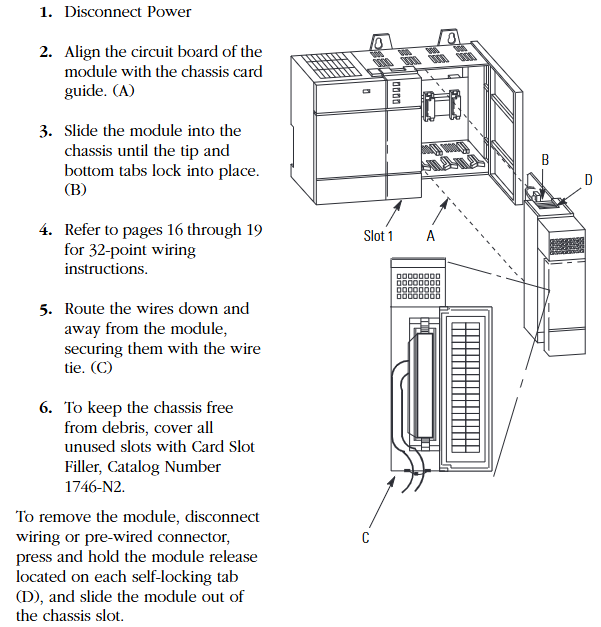
(2) Standard installation steps (power-off operation)
Power off preparation: Disconnect the chassis power supply to ensure no voltage input.
Module alignment: Align the module circuit board with the chassis card slot to avoid touching the backplane pins (to prevent static damage).
Insertion fixation: Slowly push the module into the upper and lower self-locking tabs to tighten, without the need for additional screws.
Wiring arrangement: After wiring, comb down the wires and fix them in the module slot with cable ties to avoid blocking heat dissipation or loosening.
Idle slot handling: Cover the idle slots with 1746-N2 slot filling plates to prevent dust from entering the chassis.
(3) Module disassembly
First, disconnect the external wiring or pre wired connector, press the release tabs up and down on the module, and pull out the module horizontally. Do not forcefully pull or pull it.
Core technical specifications
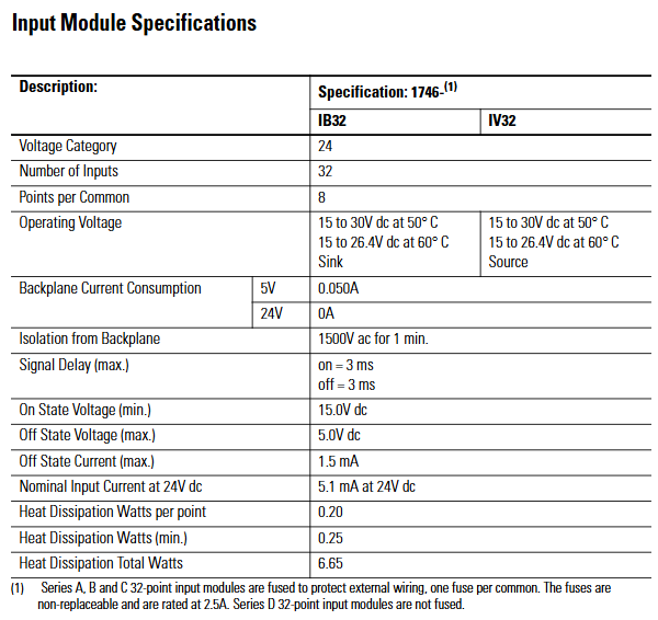
(1) Input module specifications (IB32, IV32)
Specification category 1746-IB32 (24V DC sinking input) 1746-IV32 (24V DC sourcing input)
Number of channels: 32 channels, 32 channels
8 points per group/public end (4 groups in total, isolated between groups) 8 points per public end (4 groups in total, isolated between groups)
Working voltage 15-30V DC (50 ℃), 15-26.4V DC (60 ℃) 15-30V DC (50 ℃), 15-26.4V DC (60 ℃)
Backplane current consumption 5V DC 0.050A, 24V DC 0A, 5V DC 0.050A, 24V DC 0A
Backboard isolation voltage 1500V AC (1 minute) 1500V AC (1 minute)
Signal delay (maximum) 3ms for both on/off and 3ms for both on/off
Conducting voltage (minimum) 15.0V DC 15.0V DC
Turn off voltage (maximum) 5.0V DC 5.0V DC
Turn off current (maximum) 1.5mA 1.5mA
24V DC nominal input current 5.1mA 5.1mA
Total heat dissipation power 6.65W (0.20W per point, minimum 0.25W) Total 6.65W (0.20W per point, minimum 0.25W)
Fuse protection (Series A/B/C) with 1 non replaceable 2.5A fuse per group, Series D without 1 non replaceable 2.5A fuse per group, Series D without
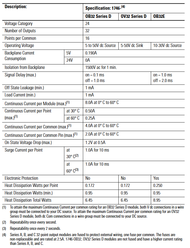
(2) Output module specifications (OB32, OB32E, OV32)
Specification category 1746-OB32 (Series D, 24V DC sourcing output) 1746-OB32E (24V DC sourcing with electronic protection) 1746-OV32 (Series D, 24V DC sinking output)
Number of channels: 32 channels, 32 channels, 32 channels
16 points per group/common end (2 groups in total, isolated between groups) 16 points per common end (2 groups in total, isolated between groups) 16 points per common end (2 groups in total, isolated between groups)
Working voltage 5-50V DC 10-30V DC 5-50V DC
Backplane current consumption 5V DC 0.190A, 24V DC 0A 5V DC 0.190A, 24V DC 0A 5V DC 0.190A, 24V DC 0A
Backboard isolation voltage 1500V AC (1 minute) 1500V AC (1 minute) 1500V AC (1 minute)
Signal delay (maximum) conducts 0.1ms, turns off 1.0ms conducts 0.1ms, turns off 1.0ms conducts 1.0ms, turns off 2.0ms
Turn off leakage current (maximum) 1mA 1mA 1mA 1mA
Minimum load current 1mA 1mA 1mA
Module total continuous current (maximum) 8.0A (0-60 ℃) 8.0A (0-60 ℃) 8.0A (0-60 ℃)
Single channel continuous current (maximum) 0.50A at 30 ℃, 0.25A at 60 ℃, 0.50A at 30 ℃, 0.25A at 60 ℃, 0.50A at 30 ℃, and 0.25A at 60 ℃
Continuous current per group (maximum) 4.0A (0-60 ℃) 4.0A (0-60 ℃) 4.0A (0-60 ℃)
Continuous current per pin (maximum) 2.0A (0-60 ℃) 2.0A (0-60 ℃) 2.0A (0-60 ℃) 2.0A (0-60 ℃)
Voltage drop during conduction (maximum) 1.2V (at 0.5A) 1.2V (at 0.5A) 1.2V (at 0.5A)
Surge current (per point) 1.0A/10ms at 30 ℃ (once per second), 1.0A/10ms at 60 ℃ (once every 2 seconds), 1.0A/10ms at 30 ℃ (once per second), 1.0A/10ms at 60 ℃ (once every 2 seconds), 1.0A/10ms at 30 ℃ (once per second), 1.0A/10ms at 60 ℃ (once every 2 seconds)
Electronic protection None (short circuit, overload thermal cut-off protection) None
The total heat dissipation power is 6.45W (0.172W per point, minimum 0.95W), 8.95W (0.250W per point, minimum 0.95W), and 6.45W (0.172W per point, minimum 0.95W)
Fuse protection (Series A/B/C): 1 non replaceable 2.5A fuse per group, Series D: None (relying on electronic protection): 1 non replaceable 2.5A fuse per group, Series D: None
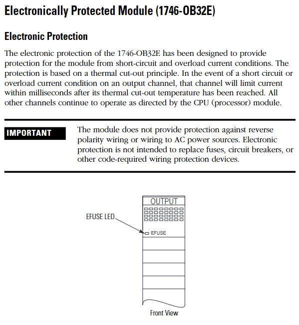
Key supplement (OB32E electronic protection features)
Protection principle: Based on thermal cut-out technology, in the event of a short circuit or overload, the faulty channel limits current within milliseconds, while other channels operate normally, and the E-Fuse LED lights up to sound an alarm.
Automatic reset: After the fault is removed, the channel cools down below the threshold and automatically recovers; Or power off and restart the module to reset, without the need to manually replace the fuse.
Limitations: It does not protect against reverse polarity wiring or AC power connection, and requires external circuit breakers to meet safety regulations.
Octal Label Kit Installation (PLC Processor Only)
(1) Composition and purpose of the kit
Contains components: octal filter label, octal door label, used to replace the default decimal label of the module and adapt to the octal addressing requirements of the PLC system.
Acquisition method: It is necessary to order separately from Allen Bradley dealers, and the model must match the I/O module catalog number (refer to manual 1747-UM011 or ACIG-PL001 price list).
(2) Installation steps
Filter label: Peel off the label from the carrier paper, align the module color bar horizontally, cover decimal numbers, and press to fix.
Door label: After peeling off, directly cover the decimal label on the inside of the chassis door to ensure consistent addressing identification.
Wiring scheme and operating specifications
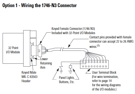
(1) Comes with connector wiring (Option 1:1746-N3 connector)
The components include: the module comes standard with a 40 pin female connector with keys (1746-N3) and crimping pins, supporting 22-26 AWG wires.
Pin assembly steps:
Stripping: Strip off the insulation layer of 4mm (5/32 inch) wire to expose the conductor.
Plug in: Insert the wire into the pin to the "wire stop" position.
Crimping: Use DDK 357J-5538 crimping tool (or Amp 90418-1 equivalent tool) for crimping; When there are no tools available, use sharp nose pliers to press the wire barrel and insulation barrel together, and then weld and fix them with 60% tin/40% lead rosin solder.
Fixed: Insert the pin into the connector, gently pull the wire to confirm that the "tang" is locked to prevent detachment.
Connector installation: Align the keyway of the module male connector (MIL-C-83503 standard) and lock it by pressing the upper and lower retaining arms.
(2) 1492 Wiring System (Option 2: Pre wiring Scheme)
1. System composition and advantages
Core components: 1492-CABLExx pre wired cable (with four lengths of 0.5m/1.0m/2.5m/5.0m), 1492-IFM40xx DIN rail terminal block (with/without LED status light), no need for on-site crimping, improving wiring efficiency.
Voltage drop reference (30 ℃/60 ℃):
Cable model: Voltage drop of power/common terminal wire (2A), voltage drop of output channel wire (0.5A), voltage drop of power/common terminal wire (2A), voltage drop of output channel wire (0.5A)
1492-CABLE005H 127mV 34mV 144mV 38mV
1492-CABLE10H 173mV 45mV 196mV 51mV
1492-CABLE25H 334mV 83mV 388mV 95mV
1492-CABLE50H 574mV 147mV 686mV 169mV
2. Terminal block label specifications
Label kit: The 1492 terminal block comes with multiple sets of sticker labels, indicating the module model (such as 1746-IB32) and the position of the "upper/lower" terminal block, distinguishing SLC (decimal) and PLC (octal) addressing.
Paste requirements: Select the corresponding label according to the module model and paste it on the outside of the terminal block. For example, label the "+V3" and "IN16" on the "upper" terminal block of module 1746-IV32 to ensure that the wiring corresponds.
(3) General Wiring Guidelines
Group isolation maintenance: When using the 1492 terminal block, it is necessary to choose a model that supports "group isolation" (such as with grouping partitions) to avoid signal crosstalk between different groups.
Voltage drop control: Calculate the total voltage drop (wire resistance x current x length) to ensure that the output module load terminal voltage is not lower than the minimum conduction voltage (such as 1.2V for OB32).
Public end connection:
Input module (IB32): Each group has 2 interconnected DC Com pins, which can be connected to only 1 pin; When it needs to exceed 2A, 2 should be connected.
Output module (OB32/OV32): Each group has 2+V DC (or DC Com) pins internally connected. When the current exceeds 2A, 2 pins must be connected to avoid pin overload.
Wiring diagrams and addressing instructions
(1) Core identification of diagrams
Double digit labeling: Each wiring diagram is labeled with both decimal (SLC system) and octal (PLC system) addresses, such as "IN 14" for SLC corresponding to "16 (octal)" for PLC.
Grouping division: Use "Wire Group 1-4" (input) or "Wire Group 1-2" (output) to clarify the wiring grouping, and the correspondence between the common terminal (COM1-4) and the signal terminal (IN/OUT 0-31) is clear.
(2) Typical module wiring example
1746-IB32 (sinking input):
The common terminal (DC Com 1-4) is connected to the negative terminal of 24V DC, the signal terminal (IN 0-31) is connected to the sensor output, and the+V DC 1-4 is connected to the positive terminal of 24V DC.
1746-OB32E (sourcing output with protection):
The common terminal (DC Com 1-2) is connected to the negative terminal of the load, the signal terminal (OUT 0-31) is connected to the positive terminal of the load, and the+V DC 1-2 is connected to the positive terminal of 24V DC. The E-Fuse LED corresponds to the fault channel.
- YOKOGAWA
- Reliance
- ADVANCED
- SEW
- ProSoft
- WATLOW
- Kongsberg
- FANUC
- VSD
- DCS
- PLC
- man-machine
- Covid-19
- Energy and Gender
- Energy Access
- Renewable Integration
- Energy Subsidies
- Energy and Water
- Net zero emission
- Energy Security
- Critical Minerals
- A-B
- petroleum
- Mine scale
- Sewage treatment
- cement
- architecture
- Industrial information
- New energy
- Automobile market
- electricity
- Construction site
- HIMA
- ABB
- Rockwell
- Schneider Modicon
- Siemens
- xYCOM
- Yaskawa
- Woodward
- BOSCH Rexroth
- MOOG
- General Electric
- American NI
- Rolls-Royce
- CTI
- Honeywell
- EMERSON
- MAN
- GE
- TRICONEX
- Control Wave
- ALSTOM
- AMAT
- STUDER
- KONGSBERG
- MOTOROLA
- DANAHER MOTION
- Bentley
- Galil
- EATON
- MOLEX
- Triconex
- DEIF
- B&W
- ZYGO
- Aerotech
- DANFOSS
- KOLLMORGEN
- Beijer
- Endress+Hauser
- schneider
- Foxboro
- KB
- REXROTH
- YAMAHA
- Johnson
- Westinghouse
- WAGO
- TOSHIBA
- TEKTRONIX
- BENDER
- BMCM
- SMC
- HITACHI
- HIRSCHMANN
- XP POWER
- Baldor
- Meggitt
- SHINKAWA
- Other Brands
- UniOP
- KUKA
- IBA
-
LTI Drives CDF30.002.C0.7 Compact Servo Controller 08685963 DC 24V Industrial Module
-
LUST LTI Drives CDB32.008.W2.4.BR.PC1 Servo Drive Industrial Motion System
-
LUST LTI Drives CDB34.003.C2.4.PC1.H15 Servo Motor Driver Industrial Control Unit
-
LUST LTI Drives CDA32.004.C1.4.H08.B0 Servo Drive Mat. 3084456 Industrial Control
-
LUST LTI Drives CDE34.005.W2.2 Industrial Servo Drive Motion Control Unit
-
LUST LTI Drives CDA34.006.W3.0 Servo Drive Software V3.70-04 Industrial Controller
-
LTI Drives CDB32.004.C2.4.SH Servo Drive Compact Motion Controller
-
Woodward 9905-373 - Digital Synchronizer And Load Controller
-
WOODWARD MAGNETIC PICKUPS - Sensor
-
WOODWARD GCP-30 - Steuertafel for Industrial Regulator Genset Control Package
-
WOODWARD GOVERNOR 9907-1183 REV A - 505 ENHANCED TURBINE CONTROL
-
WOODWARD 9907-173 REV B - Module Load Sharing 120 Volt
-
WOODWARD 9907-014 - 2301A controller
-
Woodward 9905-029 - SPM-A Synchronizer Module Rev C
-
WOODWARD 8440-1799 EASYGEN-350 REV B - Genset Controller
-
WOODWARD 5466-258 REV M - SIMPLEX DISCRETE I/O MODULE
-
Woodward 8440-1884 C - Controller Easygen 2500-5
-
Woodward 8441-1153 - Monitoring Unit 250VAC
-
WOODWARD 8406-120 REV G - EGCP-2 DIGITAL CONTROL
-
Woodward 8273-584 - Atlas-ii Digital Control
-
Woodward 8272-582 - APM Motor Control 8272582
-
Woodward 9905-377 Rev. A - 2301A Load Sharing and Speed Control
-
WOODWARD 8272-517 - Pm Motor Control
-
WOODWARD 9905-797 REV.B - DIGITAL SYNCHRONIZER AND LOAD CONTROL DSLC-D
-
WOODWARD 8272-582 - APM MOTOR CONTROL
-
Woodward Seg FP2-8-24 - Emergency Power Telecommunications Module NP2
-
WOODWARD 2001-12E2U1B1S1A - Fuel Shut Off Valve Stop Solenoid Valve 2000-4505
-
Woodward 8440-1884 K - Genset Controller Easygen-2500-5
-
Woodward 9905-760 - Linknet Termination Module
-
Woodward 8404-009 - Proact Digital Plus Front Panel Rev. H
-
Woodward 8271-651 - Digital Speed Reference
-
Woodward 3077-474C - 8605895 5501-031 D Circuit Module
-
WOODWARD 5466-257 REV.-C - NETCON 5000 MODEL REMOTE TRANSCEIVER I/O MODULE
-
Woodward 8273-101 Rev: A - 2301D Digital Load Sharing and Speed Control
-
WOODWARD 8272-799 - 2301A SPEED CONTROL WITH REMOTE REFERENCE REV:C
-
Woodward 8272-517 - PM Motor Control
-
Woodward 8290-048 8290048 Rev. F - Generator Load Sensor
-
woodward 8273-1012 rev c - 2301e Load Sharing and Speed Control
-
WOODWARD 9905-797 - DIGITAL SYNCHRONIZER AND LOAD CONTROL FOR 3 PHASE GENERATORS
-
WOODWARD 8280-3014 - 723 PLUS DIGITAL CONTROL REV NEW
-
WOODWARD 8440-1884 REV G - GENSET CONTROLLER EASYGEN-2500-5/P1
-
Woodward 8272-683 K - Digital Reference
-
WOODWARD 9907-014 - SPEED CONTROL 2301A REV H
-
Woodward Type UG-8 P/N 037260 - Governor R.P.M 1075-1650 Motor KM58-20
-
WOODWARD 9905-970 - LINKNET 6 CHANNEL 100 OHM RTD Rev:J
-
Woodward 9907-1183 Rev C - Steam Turbine Digital SCREEN 505E Turbine Control
-
Woodward 8440-1614 - GCP-30 Genset Control Package, Rev: F, Type 1, E231544
-
Woodward DC11006-304-024 - ACTUOTOR DYNA ACTUATOR - BARBER-COLMAN
-
Woodward 9905-971 - LINKNET 6 CHANNEL 100 OHM RTD Rev:K
-
Woodward DYNK-10249 - Actuator Controller Kit - DYNA 2000
-
Woodward LR21035 - MFR1 MULTI FUNCTION RELAY REV F
-
Woodward 8440-1831 - EASYGEN 3200-5 P/N: REV. G Gererator Controller
-
Woodward 8272-516 - PM MOTOR CONTROL REV J
-
Woodward 8440-2080 - EASYGEN 2000 genset controller EASYGEN-2300-5/P1
-
Woodward 505DE - Digital Control System
-
Woodward 701 - Digital Speed Control 18-40 VDC 4-20 MA
-
Woodward 8440-1799 - EASYGEN-350 REV B
-
Woodward 8272-582 - Apm Motor Control 100-220v AC/DC
-
Woodward 5501-031 D - 3077-474C 8605895 Circuit Module
-
Woodward XD1-T - XD1T55SAT TRANSFORMER DIFFERENTIAL PROTECTION RELAY
-
Woodward 8272-517 - PM Motor Control 220vac
-
Woodward 8934-658 - Repair Kit UG8D Governor
-
Woodward 5437 18 - module netcon derivative analog rev.A
-
Woodward 8272-171 A - Pm Motor Control
-
Woodward MRN3-1/2 - SEG mains uncoupling relay MRN314D mains decoupling relay
-
Woodward 9905-373 - Digital Synchronizer and Load Control 18-40 VDC Rev P
-
Woodward 5431-640 C - Dual Dynamics 1000 Series Speed Control Module
-
Woodward 5501-031 D - 3077-474C 8605895 Circuit Module
-
Woodward 9907-247 - 828 DIGITAL CONTROL
-
Woodward 8440-1855-G - EASYGEN-2200-5 /P1 12/24VDC GENSET CONTROLLER
-
Woodward NC3-2-8 (NO) - GENERATOR CONTROLLER
-
Woodward 8271-467 K - 2301 LOAD SHARING AND SPEED CONTROL PART NO:
-
Woodward 8440-2177 A - SPM-D2-10 Digital Synchronising Controller
-
Woodward LXMG1614E-14-11 - CCFL and UV Lamps Inverter Module
-
Woodward 8270-990 - signal converter
-
Woodward 9905-068 - LOW VOLTAGE 2301A LOAD SHARING & SPEED CONTOL P/N:
-
Woodward 8901-051 - BOOSTER SERVOMOTOR, SINGLE CYLINDER, 2:1
-
Woodward 8444-1024 D - MWS4-55M CONTROL MODULE UNIT
-
Woodward 5448-914 - GCP-20 Genset Control GCP-20 REV D P/n:
-
Danfoss BHA-1 018-1942 - Hydraulic Actuator
-
Woodward 9905-001 L - SPM-A SYNCHRONIZER
-
Woodward 5464-850 - Module
-
Woodward 5501-371 - Micronet Simplex Mpu Aio Rev C
-
Woodward 8272-132 B - POWER SENSOR
-
Woodward 9907-028 - SPM-A Synchronizer
-
Woodward SA-3678-AM-2 - Overspeed Electric Governor, Model ESSE2-AM
-
Woodward E8250-502 - GOVERNOR ACTUATOR
-
Woodward 8440-1884 J - Controller EASYGEN-2500-5
-
Woodward 5441-693 - DIGITAL I/O MODULE -MISSING PART
-
Woodward SA-4450 - Speed Controller APECS 3100 For Magnetic Pickup
-
Woodward 9903-466 - 701 DIGITAL SPEED CONTROL REV G
-
Woodward 1765-843 - Governor Speed Adjusting Motor P/N Type: SMM40 220V AC 50/60Hz
-
Woodward 9905-760 - Linknet Termination Module
-
Woodward 9907-247 - 828 DIGITAL CONTROL UNIT REV K
-
Woodward 5484-721 - motor
-
Woodward 8440-1734 - MFR-2 Rev.A Multi Function Relay MFR-2
-
Woodward CSC3SUWA - Controller
-
Woodward 8440-1667 - REV B SPM-D1010B/XN
-
Woodward 8406-120 - egcp-2 digital control
-
Woodward DPG-2201-002 - DIGITAL CONTROLLER REV D
-
Woodward 8272-516 - Pm Engine Control Rev J
-
Woodward 8440-1831 - EASYGEN 3200-5 P/N: REV. K - WITHOUT ACCESSORIES
-
Woodward 8273-101 - LOAD SHARING & SPEED CONTROL
-
Woodward 8440-1855-G - EASYGEN-2200-5 /P1 12/24VDC GENSET CONTROLLER
-
Woodward 9907-247 - 828 DIGITAL CONTROL UNIT REV K
-
Woodward LR21035 - MFR1 MULTI FUNCTION RELAY REV J
-
Woodward 8404-009 - PROACT DIGITAL PLUS FRONT PANEL REV J
-
Woodward 9905-204 - Rev N SPM-A synchronizer
-
Woodward 8521-367 - UG-8 P/N r R.P.M 750-1280 Governor / UG8
-
Woodward 9907-175 - Load Sharing Module Rev. B
-
Woodward 5464-645 - DRIVER MODULE REV A 2C ACT DRIVE
-
Woodward 8404-009 - PROACT DIGITAL PLUS FRONT PANEL REV J
-
Woodward 9907-175 - Load Sharing Module Rev. B
-
Woodward 8406-102 - Rev A EGCP-2 Digital Control Engine Generator 8406102
-
Woodward EASYGEN-2500-5 - Controller Genset
-
Woodward 8440-2082 - Controller
-
Woodward 8272-516 - PM MOTOR CONTROL REV J
-
Woodward 9905-373 - Digital Synchronizer and Load Control 18-40 VDC Rev P
-
Woodward 5501-429 - Actuator Controller 25mA 2 Channel , (UPP)
-
Woodward 8440-1869 - SPM-D10 Synchronizing System Control-SPM-D10B/PSY4-F-D
-
Woodward 9907-175 - Load Sharing Module Rev. A
-
Woodward 8200-224 - Servo Position Controller
-
Woodward 9906-619 - 723 PLUS DIGITAL CONTROL ( 8280-604 )
-
Woodward 8440-1519 - EASYGEN PART NO: REV: 4
-
Woodward 5501-371 - REV C MODULE- MICRONET SIMPLEX MPU & AIO FTM
-
Woodward EASYGEN-3200-5/P1 - Generator Controller Module Rev F
-
Woodward 8440-1884K - GENERATOR CONTROLLER EASYGEN-2500-5 REV,K
-
Woodward 5466-353 - REV C NETCON MAIN CHASSIS TRANSCEIVER

K-JIANG

Add: Jimei North Road, Jimei District, Xiamen, Fujian, China
Tell:+86-15305925923