
K-WANG


Allen-Bradley SLC 500 ™ 1746 series I/O modules
I/O module: Various functional modules of the 1746 series (such as digital IB/OB series, analog NI/NO series, special function modules) provide signal acquisition and control output functions for the system.
I/O rack (Chassis): includes models such as 1746-A1 (1 slot), 1746-A2 (2 slots), 1746-A7 (7 slots), 1746-A10 (10 slots), etc., used for installing modules and providing backplane buses (data and power transmission). Slot 0 is default for processor modules (such as 1747-L511), and the rest are I/O module slots.
Power modules, such as 1746-P2 (24V DC 2.0A) and 1746-P4 (24V DC 4.0A), provide stable DC power to the rack and modules. The appropriate model should be selected based on the total power consumption of the module.
Communication link: Supports industrial buses such as DH-485, ControlNet, DeviceNet, etc., to achieve data exchange between I/O modules, processors, and upper computers.
Allen-Bradley SLC 500 ™ 1746 series I/O modules
Overall architecture of 1746 I/O system
(1) System composition
The 1746 I/O system is a modular expansion unit of the SLC 500 programmable logic controller, with core components including:
I/O module: Various functional modules of the 1746 series (such as digital IB/OB series, analog NI/NO series, special function modules) provide signal acquisition and control output functions for the system.
I/O rack (Chassis): includes models such as 1746-A1 (1 slot), 1746-A2 (2 slots), 1746-A7 (7 slots), 1746-A10 (10 slots), etc., used for installing modules and providing backplane buses (data and power transmission). Slot 0 is default for processor modules (such as 1747-L511), and the rest are I/O module slots.
Power modules, such as 1746-P2 (24V DC 2.0A) and 1746-P4 (24V DC 4.0A), provide stable DC power to the rack and modules. The appropriate model should be selected based on the total power consumption of the module.
Communication link: Supports industrial buses such as DH-485, ControlNet, DeviceNet, etc., to achieve data exchange between I/O modules, processors, and upper computers.
(2) System characteristics
Modular design: Modules can be combined as needed, supporting mixed installation of digital, analog, and special functional modules, and flexibly adapting to different industrial scenarios (such as manufacturing production lines and process control).
Backplane bus technology: The rack is equipped with a 16 bit data bus with a transmission rate of 1Mbps, ensuring real-time data exchange between modules. Class 1/3 interface modules can flexibly allocate memory addresses.
Environmental adaptability: The entire series of modules comply with industrial standards, with a working temperature range of 0-60 ℃ (some modules can withstand high temperatures of 60 ℃ in the rightmost slot), humidity of 5% -95% (no condensation), and adaptability to complex environments such as workshops and outdoor control cabinets.
Redundancy and Expansion: Supports multi rack expansion (connected through communication modules), and some key modules (such as power and control modules) can be configured redundantly to improve system reliability.
Module Classification and Core Features
The 1746 series I/O modules are divided into four categories according to their functions, and the core models and characteristics of each category are as follows:
(1) Digital input module
Model Channel Number Input Type Core Characteristics Typical Applications
1746-IB16 16 16 channel 24V DC sinking 4 groups isolated (4 points/group), response time ≤ 3ms, with fuse protection (Series A/B/C) button, limit switch signal acquisition
1746-IB32 32 channel 24V DC sinking 4 groups isolated (8 points/group), low-power design, suitable for high-density signal acquisition pipeline workstation status monitoring
1746-IV16 16 16 channel 24V DC sourcing has the same structure as IB16, with opposite input polarity, and is compatible with PNP type sensor photoelectric sensor signal acquisition
1746-IV32 32 channel 24V DC sourcing 32 channel high-density design, inter group isolation, supports long-term operation in harsh environments, multi state monitoring of large equipment
(2) Digital output module
Model Channel Number Output Type Core Characteristics Typical Applications
1746-OB16 16 24V DC sourcing 2 groups isolated (8 points/group), single channel maximum current 0.5A, with fuse protection small relay and indicator light control
1746-OB32 32 channel 24V DC sourcing 32 channel high-density, 2 groups isolated (16 points/group), total continuous current 8A multi actuator synchronous control
1746-OB32E 32 channel 24V DC sourcing with built-in electronic protection (short circuit, overload thermal cut-off), automatic reset of fault channels, key equipment control (requiring fault self recovery)
1746-OV16 16 channel 24V DC sinking output polarity opposite to OB16, compatible with NPN type actuators, inter group isolation solenoid valves, and small motor control
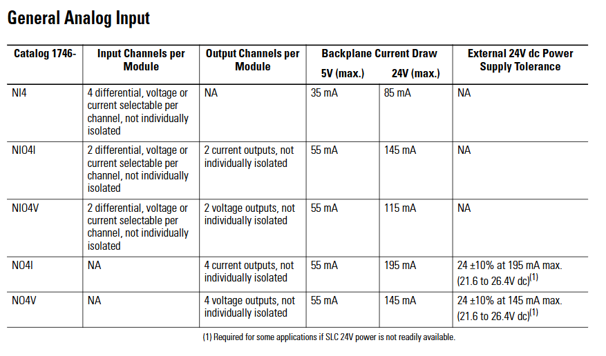
(3) Analog input module
Model Channel Number Input Signal Core Characteristics Typical Applications
1746-NI4 4-channel voltage (± 10V/0-10V, etc.), current (4-20mA, etc.) successive approximation A/D conversion, accuracy ± 0.1%, automatic temperature compensation pressure, temperature transmitter signal acquisition
1746-NI8 8-channel voltage and current, 8-channel high-density, supports single ended/differential wiring, programmable filtering (8 frequencies), multi parameter process monitoring (such as liquid level, flow rate)
1746-NR4 4-channel RTD (Pt100, Cu100, etc.) dedicated RTD signal conditioning, strong anti-interference ability, accurate ± 0.05% temperature monitoring (such as chemical reaction kettle)
1746-NT4 4-channel thermocouple (J, K, T, etc.) with built-in cold end compensation, supports open circuit detection, and is suitable for temperature acquisition in high-temperature environments such as kilns and heating furnaces
(4) Analog output module
Model Channel Number Output Signal Core Characteristics Typical Applications
1746-NO4I 4-channel current (4-20mA) D/A conversion accuracy ± 0.1%, output short-circuit protection, inter group isolation valve positioner, frequency converter control
1746-NO4V 4-channel voltage (0-10V/± 10V) with the same structure as NO4I, output type is voltage, suitable for voltage control equipment, analog speed control motor, indicator light brightness adjustment
1746-NO8V 8-channel voltage (0-10V) 8-channel high-density, total output load current ≤ 100mA, supports synchronous control of multiple devices and multi-channel analog signal output (as displayed on the dashboard)
System installation and configuration
(1) Rack and power installation
Rack selection: Choose slot positions based on the number of modules. 1746-A7 (7 slots) is suitable for small and medium-sized systems, while 1746-A10 (10 slots) is suitable for large systems; If expansion is required, multiple rack connections can be achieved through the 1747-SN module.
Power calculation: It is necessary to calculate the 5V DC and 24V DC power consumption of all modules to ensure sufficient output capacity of the power module (e.g. 1746-P2 provides 24V DC 2.0A, 1746-P4 provides 4.0A). The calculation formula is: total power consumption=∑ (5V current of each module)+∑ (24V current of each module).
Installation specifications:
The rack should be installed vertically to avoid tilting (tilt angle ≤ 5 °) and ensure good heat dissipation;
The power module should be located near the input end of the rack to reduce wire voltage drop;
The grounding resistance is ≤ 4 Ω, and the rack shell needs to be separately grounded to avoid electromagnetic interference.
(2) Module installation steps
Static protection: Wear a grounding wristband before operation, store the module in an anti-static bag, and avoid touching the back panel pins.
Power off operation: Disconnect the power supply of the power rack before installation to prevent damage to the module or backplane caused by live plugging and unplugging.
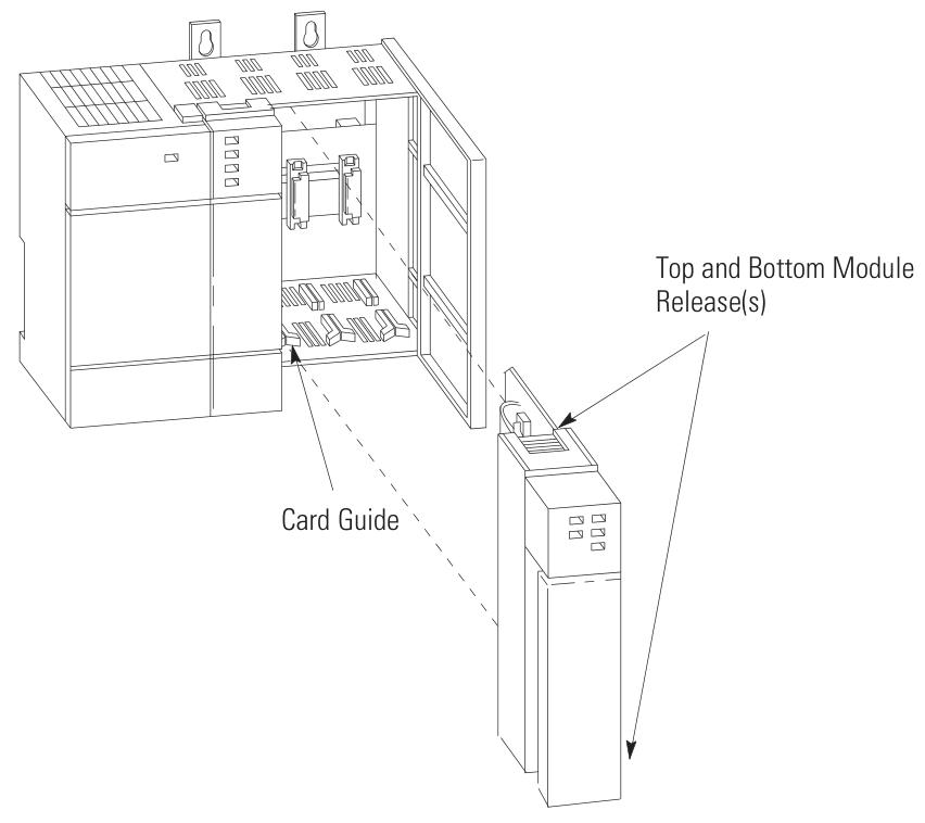
Module insertion: Align the rack slot and slowly insert the module into the upper and lower self-locking tabs to secure it, without the need for additional screws; Idle slots require installation of 1746-N2 filling plates to prevent dust from entering.
Slot selection:
The processor module (such as 1747-L511) must be installed in slot 0;
Under high temperature conditions, install the heating module (such as a 32 point I/O module) in the rightmost slot (with a temperature tolerance of 60 ℃);
The analog module needs to be kept away from strong interference sources such as frequency converters and high-power motors to reduce signal fluctuations.
(3) Module address configuration
Address allocation principle:
Digital quantity module: Each 16 channel module occupies 1 input word/output word, and the 32 channel module occupies 2 input words/output words;
Analog module: Class 1 interface module (such as 1746-NI8) occupies 8 input words and 8 output words, while Class 3 interface module adds an additional status word address;
Address range: Input image area I: 0/0-I: 255/15, output image area O: 0/0-O: 255/15, avoid address overlap.
Configuration tool: Set the module ID code (such as 1746-NI8 Class 1 ID 3526) through RSLogix 500 programming software, and assign the corresponding input/output image area address. After configuration is complete, download it to the processor.
Wiring specifications and examples
(1) General Wiring Guidelines
Wire selection:
Digital module: Recommended 22-16 AWG shielded twisted pair (such as Belden 8761) to reduce electromagnetic interference;
Analog module: requires the use of twisted pair shielded wires (such as Belden 9239), with the shielding layer grounded at one end (near the signal source end) to avoid common mode interference;
Power cord: A 24V DC power supply requires the use of 18-14 AWG wires to ensure a voltage drop of ≤ 0.5V (the wire diameter needs to be increased for long-distance wiring).
Isolation and grounding:
The group isolation module needs to ensure that the common terminals (COM) of different groups are not connected together to avoid cross group short circuits;
The grounding of the analog module needs to be independent and separate from the power grounding, with a grounding resistance of ≤ 1 Ω;
The rack shell needs to be connected to the system grounding grid through grounding terminals to prevent static electricity accumulation.
Polarity and short circuit protection:
The DC module needs to strictly distinguish between positive and negative poles, and reverse connection may burn out the module (some modules have reverse connection protection);
The load end of the output module needs to be connected in series with a suitable fuse (such as 0.5A/250V) to prevent short circuit damage to the module caused by the load.
(2) Typical module wiring example
1746-IB32 (32 channel digital input):
4 sets of common terminals (COM1-COM4) correspond to channels 0-7, 8-15, 16-23, 24-31 respectively;
COM1-COM4 is connected to the negative pole of 24V DC, channels 0-31 are connected to the sensor output terminal, and+V1-V4 is connected to the positive pole of 24V DC;
When the current of a single group exceeds 2A, both common terminals of the group need to be connected simultaneously to avoid terminal overload.
1746-OB32E (32 channel digital output):
Two sets of common terminals (+V1,+V2) correspond to channels 0-15, 16-31;
+V1 and+V2 are connected to the positive pole of 24V DC, channels 0-31 are connected to the positive pole of the load, and the negative pole of the load is connected to the negative pole of 24V DC;
When a short circuit occurs, the E-Fuse LED lights up and automatically resets after the fault is removed, without the need to replace the fuse.
1746-NI8 (8-channel analog input):
Support single ended or differential wiring, single ended signals require the negative terminal of the signal to be short circuited to the common terminal (AGND);
Differential signals (such as 4-20mA) require the signal source to be positively connected to CHx (+) and negatively connected to CHx (-), with a common mode voltage of ≤± 10.5V;
The shielding layer is connected to the top shielding terminal of the module to avoid the introduction of interference signals.
Fault diagnosis and maintenance
(1) LED status diagnosis
Each module panel is equipped with status LEDs, which provide feedback on the operating status through light on/off/flashing. The core interpretation is as follows:
Module type LED identification status fault cause solution
The digital input channel light (CH0-CH31) is not on, the channel is not enabled/the wiring is disconnected/the sensor is faulty. 1. Check the configuration word to enable the channel; 2. Check the wiring and sensor power supply
Flashing open circuit/overvoltage/module internal fault 1. Measure input voltage (15-30V DC required); 2. Replace the module for testing
The digital output channel light (CH0-CH31) is not on, the channel is not enabled, the load is short circuited, and the electronic protection is triggered. 1. Check the configuration word and load; 2. Restart after removing the faulty load
OB32E E-Fuse is always on, corresponding to channel short circuit/overload. 1. Disconnect the load to check the short circuit point; 2. Wait for the module to cool down and reset automatically
Analog module status light (STATUS) flashing configuration error/over range/open circuit 1. Check the configuration word (input type/filter); 2. Measure signal range
Channel lights (CH0-CH7) flashing, channel open circuit/signal over range 1. Check wiring integrity; 2. Confirm that the signal source output is normal
(2) Common troubleshooting
Module unresponsive:
Reason: Backplane power supply failure, incorrect module insertion, incorrect address configuration;
Investigation: 1 Measure the 5V/24V voltage of the rack (in accordance with module requirements); 2. Re plug and unplug the module and check the locking of the buckle; 3. Confirm that the ID code and address allocation are correct.
Digital input signal loss:
Reason: Sensor malfunction, loose wiring, electromagnetic interference;
Investigation: 1 Measure the output voltage of the sensor (must be ≥ 15V DC conduction); 2. Re tighten the terminals; 3. Increase shielding or keep away from interference sources.
The analog signal fluctuates greatly:
Reason: Poor shielding grounding, long signal cables, and no filtering configuration;
Investigation: 1 Ensure that the shielding layer is grounded at one end; 2. Shorten cables or use signal amplifiers; 3. Reduce the filtering frequency in the configuration word (e.g. set to 1Hz).
(3) Daily maintenance suggestions
Regular inspection: Clean the module and rack dust every 3 months, check the tightness of the wiring terminals to avoid looseness and poor contact;
Environmental control: Ensure that the temperature inside the control cabinet is ≤ 60 ℃ and the humidity is ≤ 95% (without condensation). Install a cooling fan in high-temperature environments;
Spare parts management: Key modules (such as 1746-NI8, OB32E) require spare parts to be reserved for quick replacement in case of failure, reducing downtime;
Software backup: Regularly backup RSLogix 500 project files (including module configurations) to avoid recovery difficulties caused by configuration loss.
- YOKOGAWA
- Reliance
- ADVANCED
- SEW
- ProSoft
- WATLOW
- Kongsberg
- FANUC
- VSD
- DCS
- PLC
- man-machine
- Covid-19
- Energy and Gender
- Energy Access
- Renewable Integration
- Energy Subsidies
- Energy and Water
- Net zero emission
- Energy Security
- Critical Minerals
- A-B
- petroleum
- Mine scale
- Sewage treatment
- cement
- architecture
- Industrial information
- New energy
- Automobile market
- electricity
- Construction site
- HIMA
- ABB
- Rockwell
- Schneider Modicon
- Siemens
- xYCOM
- Yaskawa
- Woodward
- BOSCH Rexroth
- MOOG
- General Electric
- American NI
- Rolls-Royce
- CTI
- Honeywell
- EMERSON
- MAN
- GE
- TRICONEX
- Control Wave
- ALSTOM
- AMAT
- STUDER
- KONGSBERG
- MOTOROLA
- DANAHER MOTION
- Bentley
- Galil
- EATON
- MOLEX
- Triconex
- DEIF
- B&W
- ZYGO
- Aerotech
- DANFOSS
- KOLLMORGEN
- Beijer
- Endress+Hauser
- schneider
- Foxboro
- KB
- REXROTH
- YAMAHA
- Johnson
- Westinghouse
- WAGO
- TOSHIBA
- TEKTRONIX
- BENDER
- BMCM
- SMC
- HITACHI
- HIRSCHMANN
- XP POWER
- Baldor
- Meggitt
- SHINKAWA
- Other Brands
- UniOP
- KUKA
- IBA
- Beckhoff
- ADLINK
-
Beckhoff EP9224-0037 - 4-Channel Power Distribution Box EtherCAT
-
Beckhoff CX2900-0026 - Solid State Flash Memory Card 20GB CFast
-
Beckhoff BK7500 - SERCOS Interface Fieldbus Bus Coupler Terminal
-
Beckhoff Ep2328-0002 - 4-Channel Input 4-Channel Output EtherCAT Box IP67
-
Beckhoff CX1020-0111 - Controller Kit Combo Interface Modules
-
B&R X20AI2237 - X20 System Analog Input Interface Module
-
Beckhoff CP2221-0010 - Multi-Touch Built-In Panel PC Touchscreen
-
Beckhoff CX1500-M310 - Fieldbus Master Interface Module 24V
-
Beckhoff CX2100-0904 - Power Charging Module Smart UPS Extension
-
Beckhoff CP3918-0000 - Multi-Touch Control Panel 18.5-Inch Monitor
-
Beckhoff CP2915-0000 - 15-Inch Multi-Touch Built-In Control Panel
-
Beckhoff CP7037-1027 - HMI Industrial Control Panel Built-In PC
-
Beckhoff EL3152 - 2-Channel Analog Input Terminal 4-20mA EtherCAT
-
Beckhoff CP6607-0000-0020 - 5.7-Inch Built-In Panel PC HMI Touch
-
Beckhoff EJ1809-0000 - 16-Channel Digital Input Pluggable Signal Level Terminal
-
Beckhoff AM8563-0N10-0000 - Synchronous Servo Motor
-
Beckhoff AX2006-S60600-520 - Compact Servo Drive Inverter
-
Beckhoff AM8053-0K20-0000 - Servo Motor with Planetary Gearbox AG3210
-
Beckhoff AM8042-0FH1-0000 - Synchronous Servo Motor
-
Rexroth R911338600 - IndraControl V HMI Terminal Beckhoff PCI Card FC9002
-
Beckhoff AX5125-0000 - 3 Phase Industrial Servo Drive 1000Hz
-
Beckhoff EP2328-0002 - 4-Channel Digital Input 4-Channel Output EtherCAT Box
-
B&R 7CP476-02 - System 2005 RTD CPU Module 3IF681.86 Interface
-
Beckhoff AX8620-0000-0000 - Power Supply Module Axis Drive System
-
Beckhoff CX1010-0111 - PLC Module CPU Controller 24V
-
Beckhoff AM8043-0H10-0000 - Synchronous Servo Motor
-
Beckhoff C6240-1009 - Control Cabinet Industrial PC Mainframe
-
Beckhoff BX8000-0000 - Bus Terminal Controller HW 4.4 Standalone
-
Beckhoff CP7721-1089-0020 - 12.1-Inch Touch Screen HMI Panel PC
-
Beckhoff CP7132-0001 - Industrial Built-In Panel PC Screen
-
Beckhoff CP2912-0010 - Multi-Touch Built-In Control Panel Display
-
Beckhoff CP2915-0000 - 15-Inch Multi-Touch Built-In Control Panel
-
Beckhoff AM8532-1EN0-0000 - Synchronous Servo Motor
-
Beckhoff AX5203-0000 - 2-Channel Digital Compact Servo Drive
-
Beckhoff CX2020-0141 - Embedded PC Core CPU Module
-
Beckhoff CP6832-0002-0010 - Built-In Industrial Control Panel Display
-
Beckhoff CX5020-0112 - Embedded PC CPU Control Module
-
Beckhoff CX5140-0175 - 4GB Embedded PC CPU Unit 24V
-
Beckhoff EL3681-0030 - Digital Multimeter Calibration Terminal EtherCAT
-
Beckhoff CP7201-1000-0000 - Industrial PC Touch Screen HMI Monitor
-
Beckhoff CP7232-1001-0000 - Industrial Panel PC Touch Screen
-
Beckhoff C6930-1032-0040 - Control Cabinet Industrial PC System
-
Beckhoff AX5125-0000 - 3 Phase Industrial Servo Drive 1000Hz
-
Beckhoff CP3916-1424-0000 - Multi-Touch Built-In Control Panel
-
B&R 1900071142 - Lemoine Fieldbus Communication Interface Module
-
Beckhoff EL2872 - 16-Channel Ribbon Cable Digital Output Terminal
-
Beckhoff CX2030-0120 - Embedded PC CPU Base Module Controller
-
Beckhoff CP3919-0000 - 19-Inch Multi-Touch Control Panel Touchscreen
-
Beckhoff AX5101-0000-0202 - Servo Driver Compact Intelligent Drive 180V
-
Beckhoff CX5130-0135 - Embedded PC Controller Module
-
Beckhoff CP3719-1061-0010 - Multi-Touch Panel PC Outer Housing Enclosure
-
Beckhoff CP3919-1033-0000 - 19-Inch Touch Industrial Panel Keyboard
-
Beckhoff CX5020-0111 - Embedded PC PLC CPU Module
-
Beckhoff FC5102-0000 - 2-Channel CANopen PCI Control Board Card
-
Beckhoff CX9001-1101 - Embedded PC CPU Network I/O System Module
-
Beckhoff CX1100-0920 - Smart Position Sensor Interface Module
-
B&R 4P3040.01-490 - Operator Panel PLC Interface Communication Module
-
Beckhoff CP2612-0000 - Dual-Touch Built-In Panel PC HMI
-
Beckhoff CP7002-1043-0010 - Touchscreen Display HMI Panel Terminal
-
Beckhoff CX9020-0115 - Embedded PC Controller Module
-
Beckhoff CX5140-0155 - 4GB Embedded PC CPU Module Die Industry
-
B&R 7DI435.7 - System 2005 Universal Digital Input Output Module
-
Bihl+Wiedemann BWU1568 - AS-i Master to Profibus Gateway Module
-
Beckhoff C6920-0070 - Control Cabinet Industrial PC 8GB Win 10
-
B&R X20AI2322 - 2-Channel Temperature Analog Input Module
-
Beckhoff CP2912-0000 - 12-Inch Touchscreen Display Monitor Screen
-
Beckhoff CP6022-1001-0010 - 15-Inch Built-In Control Panel
-
Beckhoff AM8031-0D10-0000 - Synchronous Servo Motor
-
Beckhoff CX5010-0111 - Embedded PC Controller CPU Module
-
Beckhoff CP7232-1000-0000 - Industrial Panel PC Touch Display Screen
-
Beckhoff CP7802-0011-0000 - 15-Inch Industrial Touchscreen Control Panel
-
Beckhoff C6320 - Control Cabinet Industrial PC
-
Beckhoff CX1030-0012 - Basic CPU Module Windows CE 6.0
-
Beckhoff CP2919-0000 - Installation Multi-Touch Control Panel
-
Beckhoff CX1020-0000 - Controller Set Stack System Pack
-
B&R 3DO480.6 - System 2005 Digital Output Module
-
Beckhoff EL3101 - 1-Channel Analog Input Terminal Differential +/-10V
-
Beckhoff AX8108-0200-0000 - Axis Feed Module Servo Drive
-
Beckhoff CP7802-1241-0010 - 15-Inch Industrial Touchscreen Control Panel
-
Beckhoff FC2002-0000 - 2-Channel Lightbus Data Acquisition PCI Card
-
Beckhoff CX5120-0155 - 2GB Embedded PC Intel Atom Controller
-
Beckhoff Cx9020-0111 - 1GB Basic CPU Module Embedded PC
-
Beckhoff CP6901-0001-0000 - 12-Inch Economy Built-In Control Panel
-
Beckhoff CX9020-0111 - Embedded PC CPU Basic Module
-
Beckhoff CX5130-0100 - 4GB Embedded PC CPU Module
-
Beckhoff CP2715-0010 - Multi-Touch Built-In Panel PC
-
Beckhoff CX2033-0175 - Embedded PC CPU Module Core i7
-
Beckhoff CP7201-1000-0000 - 12-Inch Touchscreen Panel PC AMAT Green Box
-
Beckhoff EL4038 - 8-Channel Analog Output Terminal 0-10V EtherCAT
-
Beckhoff CP6802-0000-0000 - Built-In Control Panel HMI Screen
-
Beckhoff AM8042-0F21-0000 - Synchronous Servo Motor
-
Beckhoff CX5120-0141 - Embedded PC Basic Controller Module
-
Beckhoff C6930-0050 - Control Cabinet Industrial PC System
-
Beckhoff CP6831-0002-0000 - Built-In Industrial Control Panel
-
Beckhoff CP6919-0001-0000 - Built-In Control Panel Display Unit
-
Beckhoff CP7201-1019-0030 - Built-In Panel PC HMI Monitor Screen
-
Beckhoff CP6809-0001-0000 - 6.5-Inch Touch Panel ELO Accutouch HMI
-
Beckhoff CX1020-0000 - Control Kit Combo Stack Units
-
Beckhoff cp3918-1012-0000 - 18.5-Inch Multi-Touch Control Panel
-
Beckhoff CX5140-0123 - 4GB Embedded PC CPU Module
-
Beckhoff C3230TP - Industrial PC Rackmount Workstation
-
Beckhoff CP6801-1006-0010 - Touch Panel HMI Display Unit
-
Beckhoff CX8010 - Embedded PC Controller Module
-
Beckhoff CP7011-0001 - Control Panel CRT Operator Pendant Monitor HMI
-
Beckhoff CX1010-0111 - Embedded PC CPU PLC Module 24V
-
Beckhoff CP2915-0000 - 15-Inch Multi-Touch Built-In Control Panel
-
Beckhoff CP7802 - Industrial Touch Screen Control Panel Monitor
-
Siemens 6AV7452-1AB00-0FB0 - Industrial PC Panel 877 Beckhoff PCI Cards
-
Beckhoff CP2612-0000 - Dual-Touch Integrated Panel Monitor Screen
-
Beckhoff CX5140-0175 - Embedded PC Core Controller
-
Beckhoff Cp6202-0001-0010 - Economy Built-In Panel PC System
-
Beckhoff C6320-0010 - Control Cabinet Industrial PC Unit
-
Beckhoff CP2919-0000 - Multi-Touch Built-In Control Panel Screen
-
Beckhoff CX9020-0111 - Embedded PC CPU Controller Module
-
B&R 3BP151.41 - System 2005 Backplane Base Module
-
Siemens 6AV7452-1AB00-0FB0 - Panel PC 877 with Beckhoff Communication Cards FC3101 FC7501
-
Beckhoff CX9001-1101 - Embedded PC System Fieldbus Module Bundle
-
Beckhoff CX1001-0122 - CPU Module PLC Controller 128MB RAM
-
Beckhoff CX5130-0175 - Embedded PC CPU Module Intel Atom Storage Card
-
Beckhoff C6140 - Industrial PC Tower Casing Pent 4 System
-
Beckhoff CX5020-0120 - Embedded PC Controller Core Module
-
Beckhoff C6017-0010 - Ultra-Compact Industrial PC
-
Beckhoff CP6809-0000-0000 - 6.5-Inch Industrial Panel Control Display
-
Beckhoff AX5021-0000-0000 - Brake Chopper Module Axis System
-
Beckhoff AM8031-0D10-0000 - Synchronous Servo Motor
-
Beckhoff CX8010 - Embedded PC Microcontroller Module
-
Beckhoff CP6202-1070-0070 - Built-In Panel PC HMI Touchscreen
-
Beckhoff C6920-0000 - Control Cabinet Industrial PC Module

K-JIANG

Add: Jimei North Road, Jimei District, Xiamen, Fujian, China
Tell:+86-15305925923