
K-WANG


Molex SST-ESR2-CLX-RLL and SST-SR4-CLX-RLL communication modules
PC hardware should have at least an Intel Pentium 4 processor, 512MB of memory, and 100MB of available hard disk space; Suggest a 17 inch/19 inch (1280 × 1024 and above resolution) monitor; CD/DVD drive, power cable, Ethernet cable, keyboard and mouse required
The PAC/PLC power ESR2 module consumes 5VDC 850mA and 24VDC 1.75mA; The SR4 module consumes 5VDC 1004mA and 24VDC 1.75mA. Please refer to the CLX 5000 modular installation and operation manual to calculate the total power load
The PC operating system supports Windows XP, Vista, 7, and 8
Other requirements: 1. Support for Rockwell Automation RSLogix 5000 Additional Instructions (AOI) requires RSLogix 5000 V16 or above, module firmware must be 2.10.2 or above (general configuration file) or 2.12.1 or above (additional configuration file/AOP), BCMS software must be 1.9 or above
Molex SST-ESR2-CLX-RLL and SST-SR4-CLX-RLL communication modules
System and hardware requirements
(1) System requirements
Category specific requirements
PC hardware should have at least an Intel Pentium 4 processor, 512MB of memory, and 100MB of available hard disk space; Suggest a 17 inch/19 inch (1280 × 1024 and above resolution) monitor; CD/DVD drive, power cable, Ethernet cable, keyboard and mouse required
The PAC/PLC power ESR2 module consumes 5VDC 850mA and 24VDC 1.75mA; The SR4 module consumes 5VDC 1004mA and 24VDC 1.75mA. Please refer to the CLX 5000 modular installation and operation manual to calculate the total power load
The PC operating system supports Windows XP, Vista, 7, and 8
Other requirements: 1. Support for Rockwell Automation RSLogix 5000 Additional Instructions (AOI) requires RSLogix 5000 V16 or above, module firmware must be 2.10.2 or above (general configuration file) or 2.12.1 or above (additional configuration file/AOP), BCMS software must be 1.9 or above
2. Support for RSLogix 5000 additional configuration files (AOP) requires RSLogix 5000 V15 or above version, module firmware 2.3.0 or above, BCMS software 1.7.0 or above, and AOP only supports maximum input/output/status INT size (250, 248, 250), small size requires 1756 universal configuration file
(2) Hardware and Packaging
package contents
The module model includes items and quantities
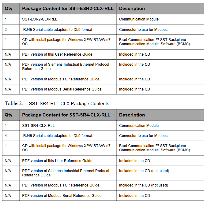
SST-ESR2-CLX-RLL 1 communication module, 2 RJ45 to DB9 serial cable adapters, 1 Windows system installation CD (including BCMS software), PDF versions of the CD including user guide, Siemens Industrial Ethernet protocol guide, Modbus TCP/serial protocol guide
SST-SR4-CLX-RLL 1 communication module, 4 RJ45 to DB9 serial cable adapters, 1 Windows system installation CD (including BCMS software), CD containing user guide, Modbus serial protocol guide PDF version (Siemens Industrial Ethernet, Modbus TCP protocol guide PDF included but not applicable)
Hardware features: All include status LEDs (COMM, SYS, OK, indicating communication/connection/initialization status respectively), RJ45 serial interface (connecting RS232/422/485 devices with transmit/receive indicator lights), USB configuration port (downloading configuration/upgrading firmware); ESR2 additionally includes an RJ45 Ethernet interface (connected to industrial networks with activity/link indicator lights), while SR4 does not have an Ethernet interface; All have self-locking tongue fixing modules, and LCD displays firmware version, connection status, IP address, and other information.
Core functions and software
(1) Core functions of the product
Differences and Commonalities of Modules
Function SST-ESR2-CLX-RLL SST-SR4-CLX-RLL
Number of interfaces: 1 Ethernet port+2 serial ports+4 serial ports
Supports protocol Modbus TCP/serial, Siemens S5/S7 communication only Modbus serial communication
Common feature 1. Supports two database addressing modes: default and extended. In default mode, 0-699 address mapping is used for CLX input/output/status tables. In extended mode, 30K address mapping can be customized
2. Support cyclic function (read and write data periodically, up to 255 per channel), which can be dynamically triggered
3. Supports AOI/AOP and CIP messaging (reading and writing databases, triggering cyclic functions)
4. Supports remote rack configuration, Listen Only mode, and can be configured as client/server (master-slave) mode
Protocol support details: Modbus supports function codes such as FC3 (read multiple registers), FC6 (write single registers), FC16 (write multiple registers), etc; Siemens S5/S7 supports reading and writing of variable types such as ABx/AWx, EBx/EWx, MBx/MWx, DBx.DBx, etc.
(2) Software and Tools
BCMS software: Brad Communication ™ The SST backplane communication module software includes Configuration Manager (managing configuration files, such as creating/uploading/downloading configurations, modifying IP addresses), Console (configuring ports/protocols/devices, creating cyclic functions, including tools such as PCInit/ReadWait/WriteWait). After installation, the configuration files, AOI files, and firmware are stored in the corresponding system paths (Windows XP/7 paths differ).
Diagnostic and management tools: including Visucyc (monitoring cyclic function status), Network Diagnostic (diagnosing ESR2 Ethernet activity), Firmware Installer (upgrading firmware), etc., supporting module connection through USB, RSLinx, TCP/IP, and other methods.
Configuration and Operation Guide
(1) Quick configuration process
Backplane communication verification: The module supports live plugging and unplugging (RIPP). During installation, align the guide rail and insert it into the rack. Configure the EtherNet/IP driver through RSLinx and browse the rack to confirm that the module is recognized (ESR2 product code 53, SR4 product code 54).
Module configuration (RSLogix 5000)
AOP configuration (recommended): You need to install the AOP installation package first, add the SST-ESR2/SR4-CLX-RLL module to RSLogix 5000, configure the slot, connection type (Output w/Status/Sten Only), RPI (5-750ms), program mode output status (such as Zero CyclicRuns), and ensure that the configuration name is consistent with the module.
General configuration file: Add 1756-MODULE, set communication format (such as Data INT with Status), assembly instance and size for input/output/configuration/status (such as input instance 1, size 250).
Initialization and Address Mode Switching: Initialize the module through Console's PCInit; The database address mode can be switched in Configuration Manager. The default mode maps the CLX table from 0-699, and the extended mode allows customization of input/output/status addresses and lengths (firmware 2.10.2 or above is required).
(2) Typical Configuration Example
Modbus TCP configuration: ESR2 can be configured as a server (select Modbus TCP protocol), client (add Modbus device, set IP address), or both client and server, creating cyclic functions (set cycle, data volume, device address, database offset).
Modbus serial configuration: Both modules can be configured as slaves (select Modbus RTU/ASCII Slave) or hosts (add Modbus slave devices, set slave numbers), supporting multi-channel master-slave hybrid configuration.
Siemens S7/S5 configuration: Only supported by ESR2, can be configured as a server/client, adding devices such as S7 300/400/1200, creating cyclic functions to read and write variables such as DBx.DWx.
Compliance and Support
(1) Compliance certification
Compliant with CE/EU, RoHS, FM (Class 1 Div 2 Groups A-D), FCC, Korean certification, RINA certification, electrical safety complies with EN 61010-1, EMC complies with EN 61000-6-2/4.
(2) Warranty and Support
Warranty: According to Molex standard warranty terms, please refer to Appendix F of the document for details.
Technical Support: You can contact Molex Canada at 216 Bathurst Drive, Waterloo, Ontario, Canada N2V 2L7; Phone: 1.775.782.3611 or 1.800.227.5514 (US only), or visit the official website Bently.com for patent information and the latest documents.
- YOKOGAWA
- Reliance
- ADVANCED
- SEW
- ProSoft
- WATLOW
- Kongsberg
- FANUC
- VSD
- DCS
- PLC
- man-machine
- Covid-19
- Energy and Gender
- Energy Access
- Renewable Integration
- Energy Subsidies
- Energy and Water
- Net zero emission
- Energy Security
- Critical Minerals
- A-B
- petroleum
- Mine scale
- Sewage treatment
- cement
- architecture
- Industrial information
- New energy
- Automobile market
- electricity
- Construction site
- HIMA
- ABB
- Rockwell
- Schneider Modicon
- Siemens
- xYCOM
- Yaskawa
- Woodward
- BOSCH Rexroth
- MOOG
- General Electric
- American NI
- Rolls-Royce
- CTI
- Honeywell
- EMERSON
- MAN
- GE
- TRICONEX
- Control Wave
- ALSTOM
- AMAT
- STUDER
- KONGSBERG
- MOTOROLA
- DANAHER MOTION
- Bentley
- Galil
- EATON
- MOLEX
- Triconex
- DEIF
- B&W
- ZYGO
- Aerotech
- DANFOSS
- KOLLMORGEN
- Beijer
- Endress+Hauser
- schneider
- Foxboro
- KB
- REXROTH
- YAMAHA
- Johnson
- Westinghouse
- WAGO
- TOSHIBA
- TEKTRONIX
- BENDER
- BMCM
- SMC
- HITACHI
- HIRSCHMANN
- XP POWER
- Baldor
- Meggitt
- SHINKAWA
- Other Brands
- UniOP
- KUKA
- IBA
- Beckhoff
- ADLINK
-
ADLINK HPCI-14S12U - Industrial Control Backplane 12PCI Backplane PCI-14S Passive Backplane
-
ADLINK PCIe-GIE74C - image acquisition card 4-CH GigE Vision PoE+ Frame Grabber
-
ADLINK PCI-8164 - control card 4-Axis Advanced Motion Controller Board
-
ADLINK PCIe-U304 - 4 Port USB3 PCIe Frame Grabbers USB Screw Hole Card
-
ADLINK PCI-9112 - Multi-Function Data Acquisition Card DAQ Card
-
ADLINK PCI-7432 - 51-12013-0A50 4-CH Isolated Numérique I/O PCI Cartes Digital I/O Card
-
ADLINK PCA-6106P3-0C1 REV.C1 - backplane 6-Slot Passive Backplane Board
-
ADLINK PCI-7224 - 24-CH Opto-Isolated Digital I/O PCI Board
-
ADLINK CPCI-7433R(G) - Digital Input Board Rear I/O CompactPCI Card
-
ADLINK EBP-13E4 - 51-46703-0A30 Industrial PC Backplane Passive Backplane
-
ADLINK PCIE-HDV62 - Image acquisition card High Definition Video Frame Grabber
-
ADLINK EBP-13E4 - 51-46703-0A30 Industrial Backplane Board Passive Backplane
-
ADLINK 90111-B1 / CPCI-6770 - PCB CPU MODULE CompactPCI Single Board Computer
-
ADLINK PCI-7248 - DATA ACQUISITION PCI CARD 48-CH Parallel Digital I/O Board
-
ADLINK PCI-7230 - 51-12003-0a50 board PCI7230 32-CH Isolated Digital I/O Card
-
ADLINK PCI2A000CB - 51-20000-0B30 Multi-Function DAQ Card Baseboard
-
ADLINK PCI-8134-005 - 4-Axis Motion Controller Card
-
ADLINK PCI-7224 - 24-CH Opto-Isolated Digital I/O PCI Card
-
ADLINK PCI-7434 - 64-CH Isolated Digital Output Card
-
ADLINK PCI-8132 - motion control card 2-Axis Servo & Stepper Controller
-
ADLINK PCI-8134 - Motion Controller PCI Card 4-Axis Controller Board
-
ADLINK PCI-8164 - Motion Control Card 51-12406-0A40 4-Axis Controller
-
ADLINK 51-12001-0C20 - Circuit Board Data Acquisition Interface Module Hardware
-
ADLINK NuPR0-840 - industrial control motherboard Full-Size PICMG CPU Board
-
ADLINK PCI-7444 - 51-12023-0A10 card 128-CH Isolated Digital Output Board
-
ADLINK PCI-1612B - data acquisition card 4-Port RS-232/422/485 Serial Communication Card
-
ADLINK PCI-6208V 009 - 8/16-CH 16-Bit Analog Output Cards PCB-I-E-482=6BX3
-
ADLINK NUPRO-935A/LV - industrial control motherboard Full-Size PICMG SBC Board
-
ADLINK PCI-9114DG - Multi-Function DAQ Card Data Acquisition PCI Card
-
ADLINK ACL-7130 - Data acquisition card Isolated Digital I/O Board
-
ADLINK ABX-6300D-4E1-BP - board ABX6300D4E1BP Video Interface Expansion Card
-
ADLINK CPCI-6940 - CPCI-6940/D1539/M16-0(EA)-000E 6U CompactPCI Processor Board
-
ADLINK NuPRO-760 - industrial control motherboard Half-Size PICMG SBC CPU Board
-
ADLINK IMB-M42H (G)-0020 - industrial control motherboard LGA1155 Micro-ATX Mainboard
-
ADLINK RTV-24 / PCI-MP4S - 51-12519-1C30 4-Channel Real Time Video Capture Board
-
ADLINK PCI-8134 - 4-Axis Servo & Stepper Motion Controller Card
-
ADLINK MXC-6101D - V.PC000.002.ST.00 Box PC Configurable Embedded Computer
-
ADLINK PCI-8134A - 51-12421-0A10 Motion Control Card 4-Axis Controller Card
-
ADLINK DIN-100S / DIN-100SA1 - Technology SCSI-II TB 100-PIN Terminal Block Board
-
ADLINK DIN-812M001 / DIN812M001 - 51-14034-0A1 51140340A1 Terminal Module Breakout Interface
-
ADLINK PCI-8164 - Servo motion control 4-Axis Advanced Controller Card
-
ADLINK PCIe-GIE64 - Acquisition card GigE Vision PoE+ Frame Grabber
-
ADLINK M-302 - Industrial control motherboard ATX PC Board Mainboard
-
ADLINK PCI-8134 - Motion Controller PCI Card 4-Axis Controller Board
-
ADLINK PCI-RTV24 - Image capture card Analog Video Frame Grabber
-
ADLINK PCI-8102 - Motion control card 2-Axis Servo & Stepper Controller Board
-
ADLINK PCI-9112 REV.B1 - Card Multi-Function Data Acquisition Card
-
ADLINK HSI-DI32-M-N / HSL-TB32-M-DIN - Discrete I/O MODULE Distributed Automation Module System
-
ADLINK PCI-7296 - IO card REV.A3 96-CH Parallel Digital I/O Card
-
ADLINK DIN-814P-A4 / 814Y - terminal board Motion Control Interface Block
-
ADLINK DIN-814P-A4 - 51-14056-0A10 PCB-I-E-2736=ZA01 Screw Terminal Board Breakout
-
ADLINK M-322 - motherboard Industrial Control Computer Mainboard
-
ADLINK NUPRO-406 REV:B1 - industrial control motherboard Full-Size PICMG CPU Board
-
ADLINK AMP-204C - card DSP-Based 4-Axis Advanced Pulse-Train Controller
-
ADLINK HPCI14S REV.B1 - industrial computer baseboard 14-Slot Passive Backplane
-
ADLINK PCI-7250 - 8-CH Relay Output & 8-CH Isolated DI PCI Card
-
ADLINK EBP-13E2 - baseplate Passive Backplane Industrial Computer Chassis Board
-
ADLINK LPCI-3488A - PCI-GPIB card 51-12801-0A30 acquisition card IEEE-488 Interface Board
-
ADLINK PCI-6216V-GL - 51-12201-0C30 16-CH 16-Bit Voltage Analog Output Card
-
ADLINK ACL-8454 - 16-CH Isolated Digital I/O & 4-CH Counter Card
-
ADLINK HPCI-9S7U - backplane Passive Backplane Compatible with NuPRO-A301 852 841 842
-
ADLINK DAQ-2010-007 - Simultaneous-Sampling Multi-Function Data Acquisition Card
-
ADLINK MP-C154 - 51-64205-0A10 Motion Control Card 4-Axis Controller Board
-
ADLINK MXE-202/mSSD16B/WiFi-BT - Matrix Rugged I/O Platform Embedded Fanless Computer
-
ADLINK CM-920-R-17 - PC/104-Plus Single Board Computer Module Intel Celeron M
-
ADLINK PCI-7250 NSMP - 8-CH Relay Output & 8-CH Isolated DI Card
-
ADLINK PCI-8164 - 4-Axis Motion Controller PCI Card W/ Cable and Breakout Box
-
ADLINK EMX-100 - Ethernet-based 4-axis Motion Controllers Distributed Motion Module
-
ADLINK PCI-8134A - Press control card 4-Axis Motion Controller Board
-
ADLINK M-845EG REV:3.2 - industrial motherboard Pentium 4 Socket 478 Micro-ATX
-
ADLINK PCI-9114A Rev A2 DG - card High-Resolution Multi-Function Data Acquisition Board
-
ADLINK IEC-915GV - REV 1.1 Industrial motherboard Socket 478 CPU Board
-
ADLINK PCI-9111DG(G) - Data Acquisition Card Multi-Function DAQ Card
-
ADLINK HPCI-15S10 REV:B2 - Industrial computer base plate Passive Backplane Board
-
ADLINK NuPR0-840 / NuPR0-840DV - industrial control motherboard Full-size PICMG CPU Board
-
ADLINK RTV-24 / PCI-MP4S - 51-12519-1C30 4-Channel Real Time Video Capture Board
-
ADLINK NUPRO-780 - industrial control motherboard Pentium III Single Board Computer
-
ADLINK PCI-7296 - 0050 card 96-CH Opto-Isolated Parallel DIO Card Set
-
ADLINK NUPRO-780 - industrial control motherboard PICMG Full-Size SBC
-
ADLINK PCI-7248 - 51-12006-0A3 002 Pci 7248 48-CH Parallel Digital I/O Card
-
ADLINK cPCI-6626 - 6U CompactPCI 2.0 Blades i7-2710QE PCB-I-E-2570=9N41
-
ADLINK MXC-6322D(G) - Industrial Fanless Computer
-
ADLINK cPCI-8168-004 - CompactPci NulPC Motion Control Board 51-36402-0A3
-
ADLINK CPCI-7300[G] - COMPACTPCI Digital I/O Card Data Acquisition
-
ADLINK CPCI-6626/2710/M4G - COMPACTPCI COMPUTER BOARD
-
ADLINK cPCI-8168-009 - cPCI NulPC Motion Control Board
-
ADLINK cPCI-6626/2710/M4G - VME CPU Board Computer Board
-
ADLINK CPCI-R6200(G)-0040 - COMPACTPCI CONTROL BOARD
-
ADLINK CPCI-3840/PM18/M1G(G)-3650 - COMPACTPCI CPU Module Single Board Computer
-
ADLINK cPCI-7248 - 48-CH Opto-22 Compatible Digital I/O Module
-
ADLINK DLAP-211-JNX - NVIDIA Jetson Xavier NX Edge AI Inference Platform
-
ADLINK cPCI-3544 - Series 4-Port RS-422/485 Isolated Serial Communications Card
-
ADLINK CM1-86DX3 - PC/104 SBC Stanley Vortex86DX3 CPU 2GB Ram
-
ADLINK DLAP-211-JNX - NVIDIA Jetson Xavier NX Edge AI Inference Platform
-
ADLINK cPCI-3544 - Series 4-Port RS-422/485 Isolated Serial Communications Card
-
ADLINK CM1-86DX3 - PC/104 SBC Stanley Vortex86DX3 CPU 2GB Ram
-
ADLINK PCI-7433 - switch value acquisition card Isolated Digital Input Card
-
ADLINK PCI-9112 - 51-12252-0D20 Multi-Function Data Acquisition Card
-
ADLINK NUPRO-A301 REV:1.4 - industrial control motherboard PICMG Full-Size SBC
-
ADLINK 51-18502-0A10 - Frame Grabber Image Acquisition Interface Card
-
ADLINK PCI-7296 - 51-12009-0A50 PCB-I-E-925=6DX1 96-CH Parallel Digital I/O Board
-
ADLINK PCI-8132 GP A2 - Motion Control Card 2-Axis Servo & Stepper Controller
-
ADLINK PCI-7442 - switch quantity card data acquisition card 64-CH Isolated Card
-
ADLINK HPX-13S4 - baseboard PICMG 1.3 Passive Backplane Chassis Baseplate
-
ADLINK NuPRO-590 / NTC-567-ZM-F36 - Single Board Computer PCB-I-E-1853=9L21 Half-Size SBC
-
ADLINK PCIe-8332 - 16-axis plate Motion Control Hardware Card
-
ADLINK NuPRO-775 REV.B1 - motherboard Pentium 4 Full-Size PICMG SBC
-
ADLINK PXI-3920 - Embedded Controller 3U PXI cPCI System Intelligence Board
-
ADLINK PCI-8134 - driver card motion control card 4-Axis Controller Board
-
ADLINK HSL-DI32-M-N-011 / HSL-TB32-M-DIN - Digital Input & Base Module PLC Distributed I/O System
-
ADLINK PCI-6216V-206 / PCI-208V 009 - 16 CH 16bit analog output card
-
ADLINK NuPro-E330 - 51-41805-0A20 PCB Single Board Computer Host Board
-
ADLINK PCI-1622C - Card 8-Port RS-232/422/485 PCI Serial Communication Board
-
ADLINK PCIe-7432 - 51-18402-0A10 Carte PCIe Avec Plage D'Entrée Élevée Isolated DIO Card
-
ADLINK PCI-7250 - PCI Acquisition Card 8-CH Relay Output Isolated DI Card
-
ADLINK PCI-7230 - 32-CH Isolated Digital I/O Card
-
ADLINK PCI-8164 - PCB 4-Axis Motion Controller Card
-
ADLINK PCI-7854 - Collection card High-Speed Link Distributed Motion Controller
-
ADLINK NuPRO-935A/LV - industrial control computer motherboard Full-Size PICMG SBC
-
ADLINK IMB-M40H - motherboard IH61-AA4 1155 LGA1155 Micro-ATX Mainboard
-
ADLINK PCI-7248 - Linhua 51-12006-0A40 48-CH Parallel Digital I/O Card
-
ADLINK HPCI-14S12U - Linhua industrial computer baseboard Passive Backplane
-
ADLINK PCI-8132 Rev.A2 - 2-Axis Servo & Stepper Motion Controller Card
-
ADLINK ACL-8111 - ISA card Multi-Function DAQ Card
-
ADLINK ACL-8111 - ISA card Multi-Function Data Acquisition Board
-
ADLINK PCI-7200 REV.A3 - Digital I/O card 12MB/s High-Speed Parallel Digital I/O
-
ADLINK PCI-7296 REV.A3 - 96-CH High-Density Opto-Isolated DIO Card
-
ADLINK PCI-7434 - 64-CH Isolated Digital Output Card

K-JIANG

Add: Jimei North Road, Jimei District, Xiamen, Fujian, China
Tell:+86-15305925923