
K-WANG
+086-15305925923
Service expert in industrial control field!


Product
Article
NameDescriptionContent
Adequate Inventory, Timely Service
pursuit of excellence


Ship control system
Equipment control system
Power monitoring system
Current position:
新闻动态
newS
Brand
ABB SYNCHROTACT®5 Operating Instructions
ABB SYNCHROTACT®5 Operating Instructions
ABB SYNCHROTACT®5 Operating Instructions
General information
1.1 Introduction
This User Manual is aimed at persons who have a basic knowledge of working with
electronic equipment, who understand electrical symbols in schematic diagrams, but
who know little or nothing about working with SYNCHROTACT 5 equipment.
The User Manual provides the information required in order to install, commission and
operate the SYNCHROTACT 5 device of types SYN 5201 and SYN 5202.
1.2 Marking of text sections
General warning
This symbol placed before the text indicates situations or conditions which can cause a
risk of death or serious injury. The text describes the procedure for preventing these
risks.
Dangerous voltages
This symbol indicates that, when handling the equipment, dangerous voltages occur
which can cause death or serious injury.
The sections of text marked with "Caution" contain information on situations which can
lead to material damage or equipment failure if the instructions are disregarded.
The sections of text marked with "Note" provide additional information. This must be
taken into consideration in order to prevent malfunctions.
Caution
Note
1.3 Purpose and use of the SYN 5201 and SYN 5202
The digital synchronizer can be used for the following applications:
• For automatic synchronization and paralleling of generators
• For automatic paralleling of synchronous and asynchronous lines, transmission lines
and busbars (incl. tap-changer matching).
• As a paralleling monitoring device (synchrocheck) for monitoring automatic or manual paralleling sequences including dead bus.
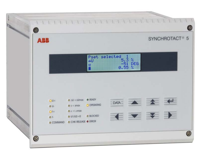
Brief description
The SYNCHROTACT 5 digital synchronizer is used for automatic synchronizing and
paralleling of generators with lines and for the paralleling of already synchronous lines.
The device is designed for system frequencies of either 50/60 Hz or 16 2
/3 Hz.
SYN 5201 is a single-channel synchronizing device whose component choice and
software design provides the highest security against incorrect paralleling.
SYN 5202 consists of two independent channels with different hardware and software.
This dual-channel property maximizes security against incorrect paralleling.
All parameters required for paralleling are stored in a parameter set. The paralleling
conditions and the characteristics of the voltage and frequency matchers are defined in
this set. With the option providing seven parameter sets, paralleling can be carried out
under different conditions or with different matcher characteristics using the same
device. Seven configurable digital inputs and outputs are available for the selection and
back indication of a parameter set.
The data which are important for commissioning and for control purposes can be
uploaded or downloaded using the PC tool SynView or, alternatively, via the keypad on
the front panel of the unit.
The following measured variables are generated from the two single-phase measuring
voltages:
Voltage U1, U2
U1 is the reference voltage e.g. line
U2 is the adjustable voltage e.g. generator.
Frequency f1, f2
f1 is the reference frequency
f2 is the adjustable frequency.
Voltage difference ΔU
ΔU = IU1I – IU2I
ΔU > 0 Adjustable voltage is lower
ΔU < 0 Adjustable voltage is higher
Slip s %100*121fs ff − =
s > 0 Adjustable frequency is less (e.g. generator is sub-synchronous)
s < 0 Adjustable frequency is greater (e.g. generator is oversynchronous)
Phase-angle difference α
21 ϕ ϕ α −=
α > 0 Adjustable frequency is lagging
α < 0 Adjustable frequency is leading
Acceleration ds/dt
[ ]ss dtdsxxx /%*2/
561∑==Δ=
(Every 0.5 s, an average value is formed from 56 measurements; sampling period: 9 ms)
ds/dt > 0 Adjustable frequency is reduced (e.g. generator accelerates)
ds/dt < 0 Adjustable frequency increases (e.g. generator is slowed down)
With SYN 5202, the measurement is carried out separately for each channel. It is
possible to carry out three-phase measurements in order to detect connection faults
(rotary field, polarity) and losses of phase.
Voltage measurement (SYN 5202: channel 1)
The two input voltages U1 and U2 are passed to the processor via high-impedance input
resistors, differential amplifiers, low-pass filters and A/D converters.
Voltage measurement channel 2 (SYN 5202 only)
The two input voltages U1 and U2 are passed through high-impedance input resistors
and differential amplifiers. The signal for the amplitude value is formed from this by
conversion and filtering . For zero-passage detection, the signal is filtered and passed
through a comparator. The signals prepared in this way are passed to the processor via
the A/D converter.
SYN 5201
SYN 5202
Frequency matcher with variable intervals
The function INVERSE f changes the way the frequency matcher functions. The pulses
are now always the same length, but the intervals are inversely proportional to the slip.
Pulse length: adjustable by means of the parameter tp fmin: tp = tp fmin
Pause interval: is calculated according to the following formula (can not be set as a
parameter):
2.2.3 Monitoring of paralleling conditions
The monitoring of the paralleling conditions can be divided into these parallel-functioning
blocks:
• voltage-carrying lines
• no-voltage lines
Paralleling of two voltage-carrying lines
The monitoring of the paralleling conditions enables a paralleling command (CHK
RELEASE) if the following conditions are fulfilled simultaneously:
• the phase-angle difference is within the tolerance band
• the slip is within the tolerance band
• the voltage difference is within the tolerance band
• the voltage does not fall below minimum voltage
• the maximum voltage is not exceeded
• the device is in operating status (OPERATING)
• nominal frequency deviation ≤ 5 Hz
Paralleling of no-voltage lines (dead bus)
A special case for the monitoring is the paralleling of no-voltage lines. A paralleling
command release is only issued if the external release signal is active and the
measuring logic enables the release at the same time. The release by the measuring
logic can be enabled if both voltages are within one of the permitted ranges. The dead
bus range can be defined as permissible for one, the other or both measuring voltages
by means of the parameters U1not, U2not and 1*2not.
The monitoring of the paralleling conditions (CHK RELEASE) releases the paralleling
command if the following conditions are fulfilled simultaneously:
• the releasing signal for dead bus (digital input) is issued
• the zero voltage(s) does not exceed the set threshold U0max
• the current voltage does not fall below the minimum voltage
• the current voltage does not exceed the maximum voltage
• the current zero voltage situation corresponds to a configuration permitted by means
of U1not, U2not, 1*2not
• the device is in Operating status (OPERATING)
2.2.4 Command generation
The command generation makes a distinction between asynchronous and synchronous
sources or no-voltage lines. Two modes, one for asynchronous and one for synchronous
sources, run in parallel, so that a source can be asynchronous or synchronous at any
time. The paralleling command is issued in the mode in which all conditions are fulfilled
first.
In SYN 5202 the actuation of the paralleling relays takes place separately in both
channels.
Asynchronous sources
It is called asynchronous sources, if the two lines to be paralleled (or generator and line)
are asynchronous before the circuit breaker is closed.
From the slip s, the acceleration ds/dt, the line frequency f1 and the set paralleling time
t on, the command generation calculates the necessary lead angle αv by which the
paralleling command is shifted forward in time so that the main contacts close exactly on
phase coincidence (see following figure)
- YOKOGAWA
- Reliance
- ADVANCED
- SEW
- ProSoft
- WATLOW
- Kongsberg
- FANUC
- VSD
- DCS
- PLC
- man-machine
- Covid-19
- Energy and Gender
- Energy Access
- Renewable Integration
- Energy Subsidies
- Energy and Water
- Net zero emission
- Energy Security
- Critical Minerals
- A-B
- petroleum
- Mine scale
- Sewage treatment
- cement
- architecture
- Industrial information
- New energy
- Automobile market
- electricity
- Construction site
- HIMA
- ABB
- Rockwell
- Schneider Modicon
- Siemens
- xYCOM
- Yaskawa
- Woodward
- BOSCH Rexroth
- MOOG
- General Electric
- American NI
- Rolls-Royce
- CTI
- Honeywell
- EMERSON
- MAN
- GE
- TRICONEX
- Control Wave
- ALSTOM
- AMAT
- STUDER
- KONGSBERG
- MOTOROLA
- DANAHER MOTION
- Bentley
- Galil
- EATON
- MOLEX
- Triconex
- DEIF
- B&W
- ZYGO
- Aerotech
- DANFOSS
- KOLLMORGEN
- Beijer
- Endress+Hauser
- schneider
- Foxboro
- KB
- REXROTH
- YAMAHA
- Johnson
- Westinghouse
- WAGO
- TOSHIBA
- TEKTRONIX
- BENDER
- BMCM
- SMC
- HITACHI
- HIRSCHMANN
- XP POWER
- Baldor
- Meggitt
- SHINKAWA
- Other Brands
- UniOP
- KUKA
- IBA
- Beckhoff
- ADLINK
51
-
Beckhoff EP9224-0037 - 4-Channel Power Distribution Box EtherCAT
-
Beckhoff CX2900-0026 - Solid State Flash Memory Card 20GB CFast
-
Beckhoff BK7500 - SERCOS Interface Fieldbus Bus Coupler Terminal
-
Beckhoff Ep2328-0002 - 4-Channel Input 4-Channel Output EtherCAT Box IP67
-
Beckhoff CX1020-0111 - Controller Kit Combo Interface Modules
-
B&R X20AI2237 - X20 System Analog Input Interface Module
-
Beckhoff CP2221-0010 - Multi-Touch Built-In Panel PC Touchscreen
-
Beckhoff CX1500-M310 - Fieldbus Master Interface Module 24V
-
Beckhoff CX2100-0904 - Power Charging Module Smart UPS Extension
-
Beckhoff CP3918-0000 - Multi-Touch Control Panel 18.5-Inch Monitor
-
Beckhoff CP2915-0000 - 15-Inch Multi-Touch Built-In Control Panel
-
Beckhoff CP7037-1027 - HMI Industrial Control Panel Built-In PC
-
Beckhoff EL3152 - 2-Channel Analog Input Terminal 4-20mA EtherCAT
-
Beckhoff CP6607-0000-0020 - 5.7-Inch Built-In Panel PC HMI Touch
-
Beckhoff EJ1809-0000 - 16-Channel Digital Input Pluggable Signal Level Terminal
-
Beckhoff AM8563-0N10-0000 - Synchronous Servo Motor
-
Beckhoff AX2006-S60600-520 - Compact Servo Drive Inverter
-
Beckhoff AM8053-0K20-0000 - Servo Motor with Planetary Gearbox AG3210
-
Beckhoff AM8042-0FH1-0000 - Synchronous Servo Motor
-
Rexroth R911338600 - IndraControl V HMI Terminal Beckhoff PCI Card FC9002
-
Beckhoff AX5125-0000 - 3 Phase Industrial Servo Drive 1000Hz
-
Beckhoff EP2328-0002 - 4-Channel Digital Input 4-Channel Output EtherCAT Box
-
B&R 7CP476-02 - System 2005 RTD CPU Module 3IF681.86 Interface
-
Beckhoff AX8620-0000-0000 - Power Supply Module Axis Drive System
-
Beckhoff CX1010-0111 - PLC Module CPU Controller 24V
-
Beckhoff AM8043-0H10-0000 - Synchronous Servo Motor
-
Beckhoff C6240-1009 - Control Cabinet Industrial PC Mainframe
-
Beckhoff BX8000-0000 - Bus Terminal Controller HW 4.4 Standalone
-
Beckhoff CP7721-1089-0020 - 12.1-Inch Touch Screen HMI Panel PC
-
Beckhoff CP7132-0001 - Industrial Built-In Panel PC Screen
-
Beckhoff CP2912-0010 - Multi-Touch Built-In Control Panel Display
-
Beckhoff CP2915-0000 - 15-Inch Multi-Touch Built-In Control Panel
-
Beckhoff AM8532-1EN0-0000 - Synchronous Servo Motor
-
Beckhoff AX5203-0000 - 2-Channel Digital Compact Servo Drive
-
Beckhoff CX2020-0141 - Embedded PC Core CPU Module
-
Beckhoff CP6832-0002-0010 - Built-In Industrial Control Panel Display
-
Beckhoff CX5020-0112 - Embedded PC CPU Control Module
-
Beckhoff CX5140-0175 - 4GB Embedded PC CPU Unit 24V
-
Beckhoff EL3681-0030 - Digital Multimeter Calibration Terminal EtherCAT
-
Beckhoff CP7201-1000-0000 - Industrial PC Touch Screen HMI Monitor
-
Beckhoff CP7232-1001-0000 - Industrial Panel PC Touch Screen
-
Beckhoff C6930-1032-0040 - Control Cabinet Industrial PC System
-
Beckhoff AX5125-0000 - 3 Phase Industrial Servo Drive 1000Hz
-
Beckhoff CP3916-1424-0000 - Multi-Touch Built-In Control Panel
-
B&R 1900071142 - Lemoine Fieldbus Communication Interface Module
-
Beckhoff EL2872 - 16-Channel Ribbon Cable Digital Output Terminal
-
Beckhoff CX2030-0120 - Embedded PC CPU Base Module Controller
-
Beckhoff CP3919-0000 - 19-Inch Multi-Touch Control Panel Touchscreen
-
Beckhoff AX5101-0000-0202 - Servo Driver Compact Intelligent Drive 180V
-
Beckhoff CX5130-0135 - Embedded PC Controller Module
-
Beckhoff CP3719-1061-0010 - Multi-Touch Panel PC Outer Housing Enclosure
-
Beckhoff CP3919-1033-0000 - 19-Inch Touch Industrial Panel Keyboard
-
Beckhoff CX5020-0111 - Embedded PC PLC CPU Module
-
Beckhoff FC5102-0000 - 2-Channel CANopen PCI Control Board Card
-
Beckhoff CX9001-1101 - Embedded PC CPU Network I/O System Module
-
Beckhoff CX1100-0920 - Smart Position Sensor Interface Module
-
B&R 4P3040.01-490 - Operator Panel PLC Interface Communication Module
-
Beckhoff CP2612-0000 - Dual-Touch Built-In Panel PC HMI
-
Beckhoff CP7002-1043-0010 - Touchscreen Display HMI Panel Terminal
-
Beckhoff CX9020-0115 - Embedded PC Controller Module
-
Beckhoff CX5140-0155 - 4GB Embedded PC CPU Module Die Industry
-
B&R 7DI435.7 - System 2005 Universal Digital Input Output Module
-
Bihl+Wiedemann BWU1568 - AS-i Master to Profibus Gateway Module
-
Beckhoff C6920-0070 - Control Cabinet Industrial PC 8GB Win 10
-
B&R X20AI2322 - 2-Channel Temperature Analog Input Module
-
Beckhoff CP2912-0000 - 12-Inch Touchscreen Display Monitor Screen
-
Beckhoff CP6022-1001-0010 - 15-Inch Built-In Control Panel
-
Beckhoff AM8031-0D10-0000 - Synchronous Servo Motor
-
Beckhoff CX5010-0111 - Embedded PC Controller CPU Module
-
Beckhoff CP7232-1000-0000 - Industrial Panel PC Touch Display Screen
-
Beckhoff CP7802-0011-0000 - 15-Inch Industrial Touchscreen Control Panel
-
Beckhoff C6320 - Control Cabinet Industrial PC
-
Beckhoff CX1030-0012 - Basic CPU Module Windows CE 6.0
-
Beckhoff CP2919-0000 - Installation Multi-Touch Control Panel
-
Beckhoff CX1020-0000 - Controller Set Stack System Pack
-
B&R 3DO480.6 - System 2005 Digital Output Module
-
Beckhoff EL3101 - 1-Channel Analog Input Terminal Differential +/-10V
-
Beckhoff AX8108-0200-0000 - Axis Feed Module Servo Drive
-
Beckhoff CP7802-1241-0010 - 15-Inch Industrial Touchscreen Control Panel
-
Beckhoff FC2002-0000 - 2-Channel Lightbus Data Acquisition PCI Card
-
Beckhoff CX5120-0155 - 2GB Embedded PC Intel Atom Controller
-
Beckhoff Cx9020-0111 - 1GB Basic CPU Module Embedded PC
-
Beckhoff CP6901-0001-0000 - 12-Inch Economy Built-In Control Panel
-
Beckhoff CX9020-0111 - Embedded PC CPU Basic Module
-
Beckhoff CX5130-0100 - 4GB Embedded PC CPU Module
-
Beckhoff CP2715-0010 - Multi-Touch Built-In Panel PC
-
Beckhoff CX2033-0175 - Embedded PC CPU Module Core i7
-
Beckhoff CP7201-1000-0000 - 12-Inch Touchscreen Panel PC AMAT Green Box
-
Beckhoff EL4038 - 8-Channel Analog Output Terminal 0-10V EtherCAT
-
Beckhoff CP6802-0000-0000 - Built-In Control Panel HMI Screen
-
Beckhoff AM8042-0F21-0000 - Synchronous Servo Motor
-
Beckhoff CX5120-0141 - Embedded PC Basic Controller Module
-
Beckhoff C6930-0050 - Control Cabinet Industrial PC System
-
Beckhoff CP6831-0002-0000 - Built-In Industrial Control Panel
-
Beckhoff CP6919-0001-0000 - Built-In Control Panel Display Unit
-
Beckhoff CP7201-1019-0030 - Built-In Panel PC HMI Monitor Screen
-
Beckhoff CP6809-0001-0000 - 6.5-Inch Touch Panel ELO Accutouch HMI
-
Beckhoff CX1020-0000 - Control Kit Combo Stack Units
-
Beckhoff cp3918-1012-0000 - 18.5-Inch Multi-Touch Control Panel
-
Beckhoff CX5140-0123 - 4GB Embedded PC CPU Module
-
Beckhoff C3230TP - Industrial PC Rackmount Workstation
-
Beckhoff CP6801-1006-0010 - Touch Panel HMI Display Unit
-
Beckhoff CX8010 - Embedded PC Controller Module
-
Beckhoff CP7011-0001 - Control Panel CRT Operator Pendant Monitor HMI
-
Beckhoff CX1010-0111 - Embedded PC CPU PLC Module 24V
-
Beckhoff CP2915-0000 - 15-Inch Multi-Touch Built-In Control Panel
-
Beckhoff CP7802 - Industrial Touch Screen Control Panel Monitor
-
Siemens 6AV7452-1AB00-0FB0 - Industrial PC Panel 877 Beckhoff PCI Cards
-
Beckhoff CP2612-0000 - Dual-Touch Integrated Panel Monitor Screen
-
Beckhoff CX5140-0175 - Embedded PC Core Controller
-
Beckhoff Cp6202-0001-0010 - Economy Built-In Panel PC System
-
Beckhoff C6320-0010 - Control Cabinet Industrial PC Unit
-
Beckhoff CP2919-0000 - Multi-Touch Built-In Control Panel Screen
-
Beckhoff CX9020-0111 - Embedded PC CPU Controller Module
-
B&R 3BP151.41 - System 2005 Backplane Base Module
-
Siemens 6AV7452-1AB00-0FB0 - Panel PC 877 with Beckhoff Communication Cards FC3101 FC7501
-
Beckhoff CX9001-1101 - Embedded PC System Fieldbus Module Bundle
-
Beckhoff CX1001-0122 - CPU Module PLC Controller 128MB RAM
-
Beckhoff CX5130-0175 - Embedded PC CPU Module Intel Atom Storage Card
-
Beckhoff C6140 - Industrial PC Tower Casing Pent 4 System
-
Beckhoff CX5020-0120 - Embedded PC Controller Core Module
-
Beckhoff C6017-0010 - Ultra-Compact Industrial PC
-
Beckhoff CP6809-0000-0000 - 6.5-Inch Industrial Panel Control Display
-
Beckhoff AX5021-0000-0000 - Brake Chopper Module Axis System
-
Beckhoff AM8031-0D10-0000 - Synchronous Servo Motor
-
Beckhoff CX8010 - Embedded PC Microcontroller Module
-
Beckhoff CP6202-1070-0070 - Built-In Panel PC HMI Touchscreen
-
Beckhoff C6920-0000 - Control Cabinet Industrial PC Module

K-JIANG

Add: Jimei North Road, Jimei District, Xiamen, Fujian, China
Tell:+86-15305925923