
K-WANG


Honeywell Safety Manager(Release 162)
Honeywell Safety Manager(Release 162)
This manual is the authoritative hardware guide for Honeywell Safety Manager Safety Instrumented Systems (SIS), applicable to industrial process safety control scenarios such as chemical, petroleum, energy, etc. The core objective is to guide engineers in completing system installation, configuration, maintenance, and troubleshooting, ensuring that the system meets SIL 1-3 safety integrity requirements and complies with international safety standards such as IEC 61508 and IEC 61511.
Basic information and security compliance in the manual
(1) Manual positioning and target audience
Core positioning: Covering the technical specifications, installation process, and maintenance methods of the entire hardware components of Safety Manager, it is the core reference for system design, debugging, and operation;
Target audience: Hardware engineers, on-site operation and maintenance personnel, system integrators, who need to have a basic understanding of PLC, industrial safety standards (such as IEC 61508), and Windows system operation ability.
(2) Safety Compliance and Certification
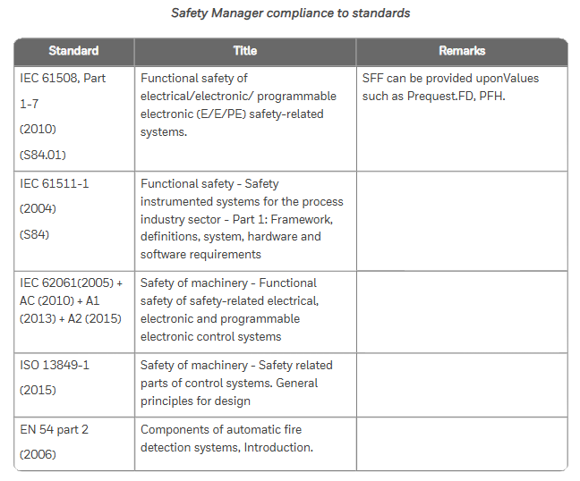
Safety standards: comply with IEC 61508 (functional safety), IEC 61511 (process industry SIS), ISO 13849-1 (mechanical safety), UL 508 (industrial control equipment), etc;
Hazardous Area Certification: ATEX, IECEx (Ex nA IIC T4, applicable to Zone 2 areas), FM 3611 (Class I/II Division 2 hazardous areas, such as chemical explosive environments);
Environmental Protection and Electromagnetic Compatibility: Compliant with RoHS Directive (Halogen Free Design) and EN 61000-6-2 (Electromagnetic Immunity in Industrial Environments), ensuring stable operation in complex industrial environments.
System hardware composition and core modules
The Safety Manager hardware system adopts a three-layer architecture of "cabinet chassis module", with core components including cabinet, controller chassis, IO chassis, power module, control processor module, input/output module, etc. The functions and technical parameters of each component are as follows:
(1) Cabinet: Physical carrier of the system
Standard configuration: Based on Rittal TS 8 series cabinets, default protection level IP20, optional IP54 upgrade; Including cooling fans (such as FANWR-24R, 24V DC with status feedback), thermostats (monitoring cabinet temperature to avoid module overheating), grounding bars (ensuring equipment grounding resistance ≤ 4 Ω), lighting fixtures (easy to maintain);
Key parameters: dimensions (such as 80 × 60 × 200cm, 80 × 80 × 200cm), weight (full load ≤ 550kg), operating temperature (-5~70 ℃, remote cabinet -40~70 ℃).
(2) Chassis: Module Installation and Signal Transmission Core
Divided into controller chassis (CPCHAS series) and IO chassis (IOCHAS series), supporting redundant/non redundant configurations to meet different safety level requirements:
Chassis type, model example, core functions, key specifications
Controller chassis CPCHAS-0001 is equipped with a control processor module to achieve system logic operations. It supports 1-2 Control processors, with a height of 4HE and a standard size of 19 inches
Non redundant IO chassis IOCHAS-0001S is equipped with non redundant IO modules, supporting 18 IO modules connected to on-site sensors/actuators, powered by 5V-R (redundant 5V)
Redundant IO chassis IOCHAS-0001R is equipped with redundant IO modules to improve system fault tolerance. It supports 9 pairs of redundant IO modules and a dual IO bus design
(3) Power Supplies: System Stable Power Supply Guarantee
Provide multiple types of power modules, supporting AC-DC conversion and redundant power supply, to meet different voltage requirements (24V/48V/60V/110V/120V DC). The core models and parameters are as follows:
Power supply model, output specifications, core characteristics, applicable scenarios
PSUNI2424 24V DC/24A, 600W dual overvoltage protection (SIL3 compatible), core controller power supply for operating temperature of -40~70 ℃
PSU-UNI2450U 25-28V DC/43-48A UL 508 certification, 100ms power-off hold, supports parallel expansion and high load IO module cluster power supply
FEEDER-24R 24V DC/63A redundant design, with status feedback relay, overcurrent protection redundant system main power feeder
(4) Control Processor Modules: The System's Brain
QPP-0002 (Quad Processor Pack): Core computing module, dual processors running synchronously, with Flash/RAM storage (battery backup, BKM-0001 module provides battery), supports Watchdog function (monitoring program execution time, memory errors), meets SIL3 requirements;
USI-0002 (Universal Safety Interface): Communication module, providing 2 channels of 10/100M Ethernet and 2 channels of universal serial communication (RS232/485), supporting interconnection with systems such as Expert PKS, with hardware firewall function;
BKM-0001 (Battery and Key Switch Module): A battery and key switch module that includes 2 lithium batteries (backup RAM data, approximately 3 months of battery life), a reset key (clear fault logs), and a forced enable key (allow IO signal forcing).
(5) I/O Modules: Field Signal Interaction
Input module: supports digital/analog signal acquisition, with fault self detection function, core models such as SDI-1624 (24V DC 16 channel digital input), SAI-1620m (16 channel analog input, 0-4V), SDI-1608 (16 channel digital input with ground fault monitoring);
Output module: supports safe digital/analog output, with short-circuit protection, core models such as SDO-0824 (24V DC 8-channel digital output), SAO-0220m (2-channel analog output, 4-20mA);
Converter module: such as BSAI-0420mI (converts 4-20mA to 0-2V, compatible with SAI-0410 module), to achieve matching between on-site signals and module inputs.
Key processes for system installation and maintenance
(1) Hardware Installation Specification
Cabinet installation: Horizontal/vertical installation should meet the requirement of heat dissipation gap (such as reserving 100mm above and below the fan), and grounding should be independent (protective ground and signal ground should be separated);
Module installation: IO modules need to press the "Key Coding" corresponding slot (such as SDI-1624 corresponding to A5/C5 hole positions) to avoid damage caused by incorrect insertion; Redundant modules need to be installed in pairs to ensure synchronous communication;
Cable connection: System interconnection cables (SIC) and communication cables (such as CCI-HSE-01 Ethernet cables) should be wired according to pin definitions to avoid reverse polarity (such as 24V DC power supply "+" connected to pin d8, "0V" connected to pin d10).
(2) Regular maintenance plan
Daily maintenance (daily/weekly): Check the LED indicator light (green normal, red fault), fan operation status, and cable joint tightness; Backup historical data (to USB drive/server);
Regular maintenance (monthly/quarterly): clean the cabinet filter (to avoid dust blockage causing overheating), test the power supply voltage (fluctuation should be ≤± 5%), and measure the cable insulation resistance (≥ 10M Ω);
Annual maintenance: Full module calibration (using original calibration tools such as 9100 calibrator), battery replacement (BKM-0001 module lithium battery replaced every 5 years), firmware upgrade (downloading the latest version from GE Digital official website).
(3) Troubleshooting and Solutions
Based on the "internal system exception" error mentioned in the Nexinstrument document, supplement the general troubleshooting logic of Safety Manager, and organize common troubleshooting solutions in the manual:
Possible causes and solutions for fault phenomena
System error "internal exception": 1. Control processor program crashes; 2. Power supply voltage fluctuations; 3. Module communication interruption: 1. Check the QPP-0002 module's Status LED (red indicates hardware failure and needs to be reset or replaced); 2. Use a multimeter to measure the 24V DC power supply (within the range of 20.4-31.2V); 3. Check the communication light of USI-0002 module (Tx/Rx light does not light up, network cable needs to be unplugged again)
IO module has no signal input 1. Sensor failure; 2. Cable breakage; 3. Module calibration expired. 1. Replace sensor for testing; 2. Use a multimeter to measure the continuity of the cable (such as the signal at pin d12 of SDI-1624 module); 3. Recalibrate the module (refer to SAI-1620m calibration process)
Power module alarm (red light on) 1. Overvoltage/undervoltage; 2. Fan malfunction; 3. Overload 1. Check the input voltage (e.g. PSU-UNI2450U input needs to be between 93-253V AC); 2. Check the fan speed (FANWR-24R speed should be ≥ 1500 RPM); 3. Reduce the number of parallel modules to avoid overloading
Communication interruption (with upper computer): 1. IP address conflict; 2. Protocol mismatch; 3. Network cable failure: 1. Reconfigure the USI-0002 module IP (to avoid conflicts with Expert PKS); 2. Confirm the communication protocol (such as Modbus TCP); 3. Replace the network cable and test the link (using a cable tester)
System configuration and expansion
Model coding rules: The hardware model includes a prefix (FS - non coated, FC - coated, FA - explosion-proof), module type (such as SDI-1624), and suffix (version number, such as V1.1), for example, "FC-SDI-1624" represents a coated 24V DC 16 channel digital input module;
Scalability: Supports adding IO channels through IO expansion modules (such as IO-0002), improving power supply reliability through redundant power supplies (such as RUSPSU-R), and achieving on-site signal terminal switching through FTA modules (such as IOTA-R24).
- YOKOGAWA
- Reliance
- ADVANCED
- SEW
- ProSoft
- WATLOW
- Kongsberg
- FANUC
- VSD
- DCS
- PLC
- man-machine
- Covid-19
- Energy and Gender
- Energy Access
- Renewable Integration
- Energy Subsidies
- Energy and Water
- Net zero emission
- Energy Security
- Critical Minerals
- A-B
- petroleum
- Mine scale
- Sewage treatment
- cement
- architecture
- Industrial information
- New energy
- Automobile market
- electricity
- Construction site
- HIMA
- ABB
- Rockwell
- Schneider Modicon
- Siemens
- xYCOM
- Yaskawa
- Woodward
- BOSCH Rexroth
- MOOG
- General Electric
- American NI
- Rolls-Royce
- CTI
- Honeywell
- EMERSON
- MAN
- GE
- TRICONEX
- Control Wave
- ALSTOM
- AMAT
- STUDER
- KONGSBERG
- MOTOROLA
- DANAHER MOTION
- Bentley
- Galil
- EATON
- MOLEX
- Triconex
- DEIF
- B&W
- ZYGO
- Aerotech
- DANFOSS
- KOLLMORGEN
- Beijer
- Endress+Hauser
- schneider
- Foxboro
- KB
- REXROTH
- YAMAHA
- Johnson
- Westinghouse
- WAGO
- TOSHIBA
- TEKTRONIX
- BENDER
- BMCM
- SMC
- HITACHI
- HIRSCHMANN
- XP POWER
- Baldor
- Meggitt
- SHINKAWA
- Other Brands
- UniOP
- KUKA
- IBA
- Beckhoff
- ADLINK
-
ADLINK HPCI-14S12U - Industrial Control Backplane 12PCI Backplane PCI-14S Passive Backplane
-
ADLINK PCIe-GIE74C - image acquisition card 4-CH GigE Vision PoE+ Frame Grabber
-
ADLINK PCI-8164 - control card 4-Axis Advanced Motion Controller Board
-
ADLINK PCIe-U304 - 4 Port USB3 PCIe Frame Grabbers USB Screw Hole Card
-
ADLINK PCI-9112 - Multi-Function Data Acquisition Card DAQ Card
-
ADLINK PCI-7432 - 51-12013-0A50 4-CH Isolated Numérique I/O PCI Cartes Digital I/O Card
-
ADLINK PCA-6106P3-0C1 REV.C1 - backplane 6-Slot Passive Backplane Board
-
ADLINK PCI-7224 - 24-CH Opto-Isolated Digital I/O PCI Board
-
ADLINK CPCI-7433R(G) - Digital Input Board Rear I/O CompactPCI Card
-
ADLINK EBP-13E4 - 51-46703-0A30 Industrial PC Backplane Passive Backplane
-
ADLINK PCIE-HDV62 - Image acquisition card High Definition Video Frame Grabber
-
ADLINK EBP-13E4 - 51-46703-0A30 Industrial Backplane Board Passive Backplane
-
ADLINK 90111-B1 / CPCI-6770 - PCB CPU MODULE CompactPCI Single Board Computer
-
ADLINK PCI-7248 - DATA ACQUISITION PCI CARD 48-CH Parallel Digital I/O Board
-
ADLINK PCI-7230 - 51-12003-0a50 board PCI7230 32-CH Isolated Digital I/O Card
-
ADLINK PCI2A000CB - 51-20000-0B30 Multi-Function DAQ Card Baseboard
-
ADLINK PCI-8134-005 - 4-Axis Motion Controller Card
-
ADLINK PCI-7224 - 24-CH Opto-Isolated Digital I/O PCI Card
-
ADLINK PCI-7434 - 64-CH Isolated Digital Output Card
-
ADLINK PCI-8132 - motion control card 2-Axis Servo & Stepper Controller
-
ADLINK PCI-8134 - Motion Controller PCI Card 4-Axis Controller Board
-
ADLINK PCI-8164 - Motion Control Card 51-12406-0A40 4-Axis Controller
-
ADLINK 51-12001-0C20 - Circuit Board Data Acquisition Interface Module Hardware
-
ADLINK NuPR0-840 - industrial control motherboard Full-Size PICMG CPU Board
-
ADLINK PCI-7444 - 51-12023-0A10 card 128-CH Isolated Digital Output Board
-
ADLINK PCI-1612B - data acquisition card 4-Port RS-232/422/485 Serial Communication Card
-
ADLINK PCI-6208V 009 - 8/16-CH 16-Bit Analog Output Cards PCB-I-E-482=6BX3
-
ADLINK NUPRO-935A/LV - industrial control motherboard Full-Size PICMG SBC Board
-
ADLINK PCI-9114DG - Multi-Function DAQ Card Data Acquisition PCI Card
-
ADLINK ACL-7130 - Data acquisition card Isolated Digital I/O Board
-
ADLINK ABX-6300D-4E1-BP - board ABX6300D4E1BP Video Interface Expansion Card
-
ADLINK CPCI-6940 - CPCI-6940/D1539/M16-0(EA)-000E 6U CompactPCI Processor Board
-
ADLINK NuPRO-760 - industrial control motherboard Half-Size PICMG SBC CPU Board
-
ADLINK IMB-M42H (G)-0020 - industrial control motherboard LGA1155 Micro-ATX Mainboard
-
ADLINK RTV-24 / PCI-MP4S - 51-12519-1C30 4-Channel Real Time Video Capture Board
-
ADLINK PCI-8134 - 4-Axis Servo & Stepper Motion Controller Card
-
ADLINK MXC-6101D - V.PC000.002.ST.00 Box PC Configurable Embedded Computer
-
ADLINK PCI-8134A - 51-12421-0A10 Motion Control Card 4-Axis Controller Card
-
ADLINK DIN-100S / DIN-100SA1 - Technology SCSI-II TB 100-PIN Terminal Block Board
-
ADLINK DIN-812M001 / DIN812M001 - 51-14034-0A1 51140340A1 Terminal Module Breakout Interface
-
ADLINK PCI-8164 - Servo motion control 4-Axis Advanced Controller Card
-
ADLINK PCIe-GIE64 - Acquisition card GigE Vision PoE+ Frame Grabber
-
ADLINK M-302 - Industrial control motherboard ATX PC Board Mainboard
-
ADLINK PCI-8134 - Motion Controller PCI Card 4-Axis Controller Board
-
ADLINK PCI-RTV24 - Image capture card Analog Video Frame Grabber
-
ADLINK PCI-8102 - Motion control card 2-Axis Servo & Stepper Controller Board
-
ADLINK PCI-9112 REV.B1 - Card Multi-Function Data Acquisition Card
-
ADLINK HSI-DI32-M-N / HSL-TB32-M-DIN - Discrete I/O MODULE Distributed Automation Module System
-
ADLINK PCI-7296 - IO card REV.A3 96-CH Parallel Digital I/O Card
-
ADLINK DIN-814P-A4 / 814Y - terminal board Motion Control Interface Block
-
ADLINK DIN-814P-A4 - 51-14056-0A10 PCB-I-E-2736=ZA01 Screw Terminal Board Breakout
-
ADLINK M-322 - motherboard Industrial Control Computer Mainboard
-
ADLINK NUPRO-406 REV:B1 - industrial control motherboard Full-Size PICMG CPU Board
-
ADLINK AMP-204C - card DSP-Based 4-Axis Advanced Pulse-Train Controller
-
ADLINK HPCI14S REV.B1 - industrial computer baseboard 14-Slot Passive Backplane
-
ADLINK PCI-7250 - 8-CH Relay Output & 8-CH Isolated DI PCI Card
-
ADLINK EBP-13E2 - baseplate Passive Backplane Industrial Computer Chassis Board
-
ADLINK LPCI-3488A - PCI-GPIB card 51-12801-0A30 acquisition card IEEE-488 Interface Board
-
ADLINK PCI-6216V-GL - 51-12201-0C30 16-CH 16-Bit Voltage Analog Output Card
-
ADLINK ACL-8454 - 16-CH Isolated Digital I/O & 4-CH Counter Card
-
ADLINK HPCI-9S7U - backplane Passive Backplane Compatible with NuPRO-A301 852 841 842
-
ADLINK DAQ-2010-007 - Simultaneous-Sampling Multi-Function Data Acquisition Card
-
ADLINK MP-C154 - 51-64205-0A10 Motion Control Card 4-Axis Controller Board
-
ADLINK MXE-202/mSSD16B/WiFi-BT - Matrix Rugged I/O Platform Embedded Fanless Computer
-
ADLINK CM-920-R-17 - PC/104-Plus Single Board Computer Module Intel Celeron M
-
ADLINK PCI-7250 NSMP - 8-CH Relay Output & 8-CH Isolated DI Card
-
ADLINK PCI-8164 - 4-Axis Motion Controller PCI Card W/ Cable and Breakout Box
-
ADLINK EMX-100 - Ethernet-based 4-axis Motion Controllers Distributed Motion Module
-
ADLINK PCI-8134A - Press control card 4-Axis Motion Controller Board
-
ADLINK M-845EG REV:3.2 - industrial motherboard Pentium 4 Socket 478 Micro-ATX
-
ADLINK PCI-9114A Rev A2 DG - card High-Resolution Multi-Function Data Acquisition Board
-
ADLINK IEC-915GV - REV 1.1 Industrial motherboard Socket 478 CPU Board
-
ADLINK PCI-9111DG(G) - Data Acquisition Card Multi-Function DAQ Card
-
ADLINK HPCI-15S10 REV:B2 - Industrial computer base plate Passive Backplane Board
-
ADLINK NuPR0-840 / NuPR0-840DV - industrial control motherboard Full-size PICMG CPU Board
-
ADLINK RTV-24 / PCI-MP4S - 51-12519-1C30 4-Channel Real Time Video Capture Board
-
ADLINK NUPRO-780 - industrial control motherboard Pentium III Single Board Computer
-
ADLINK PCI-7296 - 0050 card 96-CH Opto-Isolated Parallel DIO Card Set
-
ADLINK NUPRO-780 - industrial control motherboard PICMG Full-Size SBC
-
ADLINK PCI-7248 - 51-12006-0A3 002 Pci 7248 48-CH Parallel Digital I/O Card
-
ADLINK cPCI-6626 - 6U CompactPCI 2.0 Blades i7-2710QE PCB-I-E-2570=9N41
-
ADLINK MXC-6322D(G) - Industrial Fanless Computer
-
ADLINK cPCI-8168-004 - CompactPci NulPC Motion Control Board 51-36402-0A3
-
ADLINK CPCI-7300[G] - COMPACTPCI Digital I/O Card Data Acquisition
-
ADLINK CPCI-6626/2710/M4G - COMPACTPCI COMPUTER BOARD
-
ADLINK cPCI-8168-009 - cPCI NulPC Motion Control Board
-
ADLINK cPCI-6626/2710/M4G - VME CPU Board Computer Board
-
ADLINK CPCI-R6200(G)-0040 - COMPACTPCI CONTROL BOARD
-
ADLINK CPCI-3840/PM18/M1G(G)-3650 - COMPACTPCI CPU Module Single Board Computer
-
ADLINK cPCI-7248 - 48-CH Opto-22 Compatible Digital I/O Module
-
ADLINK DLAP-211-JNX - NVIDIA Jetson Xavier NX Edge AI Inference Platform
-
ADLINK cPCI-3544 - Series 4-Port RS-422/485 Isolated Serial Communications Card
-
ADLINK CM1-86DX3 - PC/104 SBC Stanley Vortex86DX3 CPU 2GB Ram
-
ADLINK DLAP-211-JNX - NVIDIA Jetson Xavier NX Edge AI Inference Platform
-
ADLINK cPCI-3544 - Series 4-Port RS-422/485 Isolated Serial Communications Card
-
ADLINK CM1-86DX3 - PC/104 SBC Stanley Vortex86DX3 CPU 2GB Ram
-
ADLINK PCI-7433 - switch value acquisition card Isolated Digital Input Card
-
ADLINK PCI-9112 - 51-12252-0D20 Multi-Function Data Acquisition Card
-
ADLINK NUPRO-A301 REV:1.4 - industrial control motherboard PICMG Full-Size SBC
-
ADLINK 51-18502-0A10 - Frame Grabber Image Acquisition Interface Card
-
ADLINK PCI-7296 - 51-12009-0A50 PCB-I-E-925=6DX1 96-CH Parallel Digital I/O Board
-
ADLINK PCI-8132 GP A2 - Motion Control Card 2-Axis Servo & Stepper Controller
-
ADLINK PCI-7442 - switch quantity card data acquisition card 64-CH Isolated Card
-
ADLINK HPX-13S4 - baseboard PICMG 1.3 Passive Backplane Chassis Baseplate
-
ADLINK NuPRO-590 / NTC-567-ZM-F36 - Single Board Computer PCB-I-E-1853=9L21 Half-Size SBC
-
ADLINK PCIe-8332 - 16-axis plate Motion Control Hardware Card
-
ADLINK NuPRO-775 REV.B1 - motherboard Pentium 4 Full-Size PICMG SBC
-
ADLINK PXI-3920 - Embedded Controller 3U PXI cPCI System Intelligence Board
-
ADLINK PCI-8134 - driver card motion control card 4-Axis Controller Board
-
ADLINK HSL-DI32-M-N-011 / HSL-TB32-M-DIN - Digital Input & Base Module PLC Distributed I/O System
-
ADLINK PCI-6216V-206 / PCI-208V 009 - 16 CH 16bit analog output card
-
ADLINK NuPro-E330 - 51-41805-0A20 PCB Single Board Computer Host Board
-
ADLINK PCI-1622C - Card 8-Port RS-232/422/485 PCI Serial Communication Board
-
ADLINK PCIe-7432 - 51-18402-0A10 Carte PCIe Avec Plage D'Entrée Élevée Isolated DIO Card
-
ADLINK PCI-7250 - PCI Acquisition Card 8-CH Relay Output Isolated DI Card
-
ADLINK PCI-7230 - 32-CH Isolated Digital I/O Card
-
ADLINK PCI-8164 - PCB 4-Axis Motion Controller Card
-
ADLINK PCI-7854 - Collection card High-Speed Link Distributed Motion Controller
-
ADLINK NuPRO-935A/LV - industrial control computer motherboard Full-Size PICMG SBC
-
ADLINK IMB-M40H - motherboard IH61-AA4 1155 LGA1155 Micro-ATX Mainboard
-
ADLINK PCI-7248 - Linhua 51-12006-0A40 48-CH Parallel Digital I/O Card
-
ADLINK HPCI-14S12U - Linhua industrial computer baseboard Passive Backplane
-
ADLINK PCI-8132 Rev.A2 - 2-Axis Servo & Stepper Motion Controller Card
-
ADLINK ACL-8111 - ISA card Multi-Function DAQ Card
-
ADLINK ACL-8111 - ISA card Multi-Function Data Acquisition Board
-
ADLINK PCI-7200 REV.A3 - Digital I/O card 12MB/s High-Speed Parallel Digital I/O
-
ADLINK PCI-7296 REV.A3 - 96-CH High-Density Opto-Isolated DIO Card
-
ADLINK PCI-7434 - 64-CH Isolated Digital Output Card

K-JIANG

Add: Jimei North Road, Jimei District, Xiamen, Fujian, China
Tell:+86-15305925923