
K-WANG


ABB REF54 series relay protection device
ABB REF54 series relay protection device
This document is a technical document released by ABB for the REF54 series relay protection devices (presumably protection devices for medium and low voltage distribution systems, such as REF541, REF542, etc.). The core revolves around the functional characteristics, technical specifications, configuration logic, and application scenarios of the devices, aiming to guide electrical engineers in selecting devices, setting parameters, installing, debugging, and operating to ensure reliable protection of transformers, busbars, feeders, and other equipment in distribution networks (such as industrial plants, commercial buildings, and power distribution stations), in compliance with international relay protection standards such as IEC 60255.
Product core positioning and applicable scenarios
1. Core functional positioning
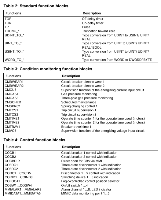
The REF54 series is a multifunctional digital relay protection device launched by ABB, integrating the four core functions of "protection, control, measurement, and communication". It can replace traditional discrete protection relays and measurement instruments, achieve comprehensive monitoring and rapid response to faults of distribution equipment, and cover specific functions:
Protection function: Provides overcurrent protection (inverse time limit/definite time limit), overload protection, ground fault protection, short circuit protection, undervoltage/overvoltage protection, etc. for different protected objects (transformers, feeders, busbars), supports protection setting grading (adapted to different operating conditions).
Control function: Supports local/remote operation (such as circuit breaker opening and closing, constant value switching), has operation locking logic (to prevent misoperation), and can be connected to external control signals (such as PLC, SCADA system instructions).
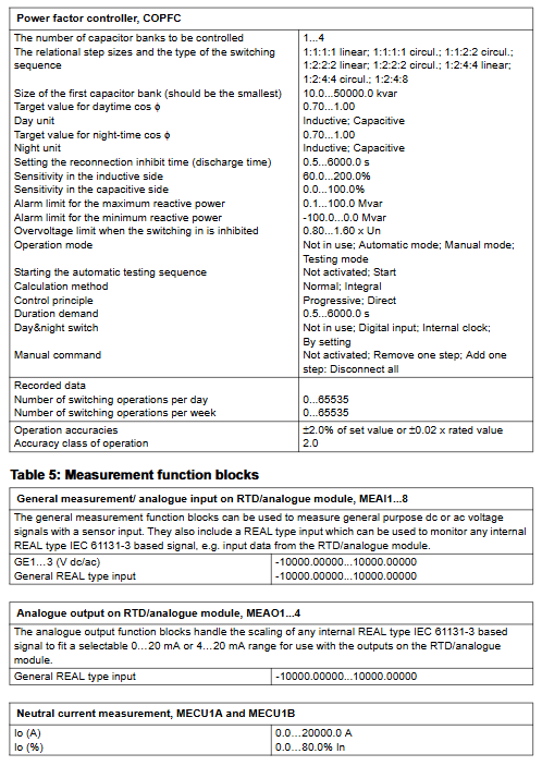
Measurement function: Real time collection of electrical parameters, including three-phase current, voltage, power (active/reactive), power factor, and electrical energy (cumulative/instantaneous), with a measurement accuracy of 0.2 level (compliant with IEC 60688 standard).
Event recording: Automatically record fault events (fault type, occurrence time, fault time parameters), operation records (opening and closing operations, constant value modification), storage capacity supports ≥ 1000 events, facilitating fault traceability and operation and maintenance analysis.
2. Typical Applicable Scenarios
Industrial power distribution: used for the protection of factory workshop power distribution circuits and motor control circuits, adapted to high load, multi start stop industrial environments, and supporting linkage with ABB AC500 and other PLC systems;
Commercial and civil buildings: As feeder protection devices for office buildings and residential distribution stations, they achieve overload and short circuit protection for lighting, air conditioning, and other loads;
Power distribution network: used for low-voltage protection of transformers in 10kV/0.4kV distribution stations, in conjunction with ABB SCADA system to achieve remote monitoring and unmanned operation.
Key technical specifications and performance parameters
1. Electrical and protective characteristics
Category core specifications (general reference, specific models may vary slightly)
Input parameter current input: 5A/1A (standard CT secondary current); Voltage input: 100V/220V (PT secondary voltage, line voltage/phase voltage optional); Frequency: 50/60Hz (automatic recognition)
Protection range for overcurrent protection: 0.1-10Ie (Ie is the rated current); Overload protection: 0.5-1.5Ie; Ground fault protection: 0.05-5Ie; Action time limit: 0.01-300s
Measurement accuracy current/voltage: ± 0.2%; Power/electric energy: ± 0.5%; Frequency: ± 0.01Hz
Trip outlet 2-4 sets of normally open/normally closed relay contacts (rated load: 5A@250VAC /30VDC), Support self checking of trip circuit (to avoid contact adhesion causing misoperation)
2. Communication and interface characteristics
Communication interface: Standard configuration includes 1 RS485 (supporting Modbus RTU protocol), optional 1 Ethernet (Ethernet/IP or Modbus TCP), supporting interconnection with upper computer (such as ABB MicroSCADA system), HMI or third-party control system to achieve data upload and remote control;
Local interface: Equipped with an LCD display screen (128 × 64 pixels, supporting Chinese/English display), 4 operation buttons (for setting settings and event queries), and some models come with a USB interface (for data export and firmware upgrade).
3. Environmental and compliance characteristics
Environmental adaptability: working temperature -25~+70 ℃ (wide temperature design), storage temperature -40~+85 ℃; Relative humidity ranging from 5% to 95% (without condensation); Anti vibration level 5g (10-500Hz, compliant with IEC 60068-2-6), suitable for complex environments inside distribution cabinets;
Compliance certification: Complies with IEC 60255 (General Standard for Relay Protection Devices), IEC 61000-6-2 (Electromagnetic Immunity for Industrial Environments), CE certification, UL 508 certification, and some models have passed ATEX Zone 2 explosion-proof certification (applicable to distribution in hazardous areas).
Configuration and operation points
1. Protection of fixed value configuration logic
The device supports configuring settings according to the "protection group" to meet different operating mode requirements (such as "normal operation", "maintenance mode", "backup power on/off"). The core configuration steps are as follows:
Enter the "Fixed Value Settings" menu (requires administrator privileges, password protection);
Select the type of protection object (such as "feeder protection" or "transformer protection"), and the system will automatically load the default protection logic template;
Adjust specific settings (such as overcurrent settings and action time limits), support real-time preview of the effective range of settings (to avoid exceeding the device's allowable values);
Save the set value and activate it (some models require restarting the device or manually switching the protection group), and automatically record the set value modification event after activation.
2. Installation and wiring specifications
Installation method: Using standard DIN rail installation (35mm rail), compact size (width x height x depth about 90 x 140 x 180mm), suitable for installation inside 19 inch distribution cabinet doors or cabinets, with a reserved installation spacing of ≥ 50mm (for heat dissipation);
Wiring requirements:
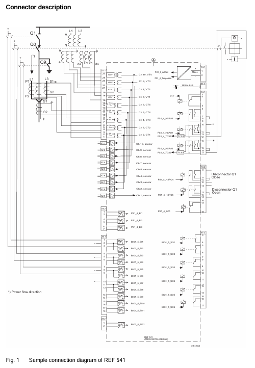
Current circuit: Attention should be paid to the polarity of the CT secondary side wiring ("P1" in "P2" out) to avoid reverse connection and protection misoperation;
Voltage circuit: PT wiring needs to distinguish between line voltage (such as Uab, Ubc) and phase voltage (such as Ua, Ub, Uc) to ensure correct measurement and protection logic;
Communication circuit: RS485 uses shielded twisted pair cables (shielded layer single ended grounding), Ethernet uses CAT5e or above network cables, and the distance between strong current cables is ≥ 100mm to reduce interference.
Maintenance and troubleshooting
1. Regular maintenance plan
Daily inspection (daily/weekly): Check the LCD display screen to confirm that there are no fault alarms (such as "CT disconnection" or "PT voltage loss"); Check the status of the indicator lights (green power light on, flashing running light is normal);
Regular maintenance (monthly/quarterly): Clean the surface dust of the device (wipe with a dry dust-free cloth); Check the tightness of the wiring terminals (to avoid looseness and poor contact); Export event records and measurement data through the upper computer, analyze equipment operation trends;
Annual maintenance: Testing the accuracy of protection settings (using relay protection testers to simulate fault signals and verify the correctness of actions); Check the tripping outlet relay contacts (measure the continuity of the contacts with a multimeter); Upgrade device firmware (download the latest version from ABB's official website and upgrade via USB or Ethernet).
2. Common faults and solutions
Possible causes and solutions for the fault phenomenon
The power light is not on, the power supply is not powered, the power module is faulty, and the wiring is loose. Check the output of the 220V/110V DC power supply; Re plug and unplug the power supply wiring; Replace the power module
The protection device refuses to operate and the protection setting is incorrect, the CT/PT wiring is reversed, and the tripping circuit fault occurs. Re check the protection setting (such as whether the overcurrent setting is lower than the fault current); Check CT/PT polarity; Test the tripping outlet relay (simulate the tripping signal with a tester)
Communication interruption (with upper computer), communication line failure, IP address conflict, protocol mismatch, replacement of communication line; Reconfigure RS485 address/IP address (to avoid conflicts); Confirm that the communication protocol is consistent (such as Modbus RTU slave address)
Display the "CT disconnection" alarm for CT circuit open circuit, CT fault, and internal sampling circuit fault. Check the CT secondary side wiring (whether it is open circuit); Measure the CT circuit resistance with a multimeter (normally ≤ 5 Ω); Contact ABB for after-sales inspection of the sampling circuit of the device
- YOKOGAWA
- Reliance
- ADVANCED
- SEW
- ProSoft
- WATLOW
- Kongsberg
- FANUC
- VSD
- DCS
- PLC
- man-machine
- Covid-19
- Energy and Gender
- Energy Access
- Renewable Integration
- Energy Subsidies
- Energy and Water
- Net zero emission
- Energy Security
- Critical Minerals
- A-B
- petroleum
- Mine scale
- Sewage treatment
- cement
- architecture
- Industrial information
- New energy
- Automobile market
- electricity
- Construction site
- HIMA
- ABB
- Rockwell
- Schneider Modicon
- Siemens
- xYCOM
- Yaskawa
- Woodward
- BOSCH Rexroth
- MOOG
- General Electric
- American NI
- Rolls-Royce
- CTI
- Honeywell
- EMERSON
- MAN
- GE
- TRICONEX
- Control Wave
- ALSTOM
- AMAT
- STUDER
- KONGSBERG
- MOTOROLA
- DANAHER MOTION
- Bentley
- Galil
- EATON
- MOLEX
- Triconex
- DEIF
- B&W
- ZYGO
- Aerotech
- DANFOSS
- KOLLMORGEN
- Beijer
- Endress+Hauser
- schneider
- Foxboro
- KB
- REXROTH
- YAMAHA
- Johnson
- Westinghouse
- WAGO
- TOSHIBA
- TEKTRONIX
- BENDER
- BMCM
- SMC
- HITACHI
- HIRSCHMANN
- XP POWER
- Baldor
- Meggitt
- SHINKAWA
- Other Brands
- UniOP
- KUKA
- IBA
- Beckhoff
- ADLINK
-
ADLINK HPCI-14S12U - Industrial Control Backplane 12PCI Backplane PCI-14S Passive Backplane
-
ADLINK PCIe-GIE74C - image acquisition card 4-CH GigE Vision PoE+ Frame Grabber
-
ADLINK PCI-8164 - control card 4-Axis Advanced Motion Controller Board
-
ADLINK PCIe-U304 - 4 Port USB3 PCIe Frame Grabbers USB Screw Hole Card
-
ADLINK PCI-9112 - Multi-Function Data Acquisition Card DAQ Card
-
ADLINK PCI-7432 - 51-12013-0A50 4-CH Isolated Numérique I/O PCI Cartes Digital I/O Card
-
ADLINK PCA-6106P3-0C1 REV.C1 - backplane 6-Slot Passive Backplane Board
-
ADLINK PCI-7224 - 24-CH Opto-Isolated Digital I/O PCI Board
-
ADLINK CPCI-7433R(G) - Digital Input Board Rear I/O CompactPCI Card
-
ADLINK EBP-13E4 - 51-46703-0A30 Industrial PC Backplane Passive Backplane
-
ADLINK PCIE-HDV62 - Image acquisition card High Definition Video Frame Grabber
-
ADLINK EBP-13E4 - 51-46703-0A30 Industrial Backplane Board Passive Backplane
-
ADLINK 90111-B1 / CPCI-6770 - PCB CPU MODULE CompactPCI Single Board Computer
-
ADLINK PCI-7248 - DATA ACQUISITION PCI CARD 48-CH Parallel Digital I/O Board
-
ADLINK PCI-7230 - 51-12003-0a50 board PCI7230 32-CH Isolated Digital I/O Card
-
ADLINK PCI2A000CB - 51-20000-0B30 Multi-Function DAQ Card Baseboard
-
ADLINK PCI-8134-005 - 4-Axis Motion Controller Card
-
ADLINK PCI-7224 - 24-CH Opto-Isolated Digital I/O PCI Card
-
ADLINK PCI-7434 - 64-CH Isolated Digital Output Card
-
ADLINK PCI-8132 - motion control card 2-Axis Servo & Stepper Controller
-
ADLINK PCI-8134 - Motion Controller PCI Card 4-Axis Controller Board
-
ADLINK PCI-8164 - Motion Control Card 51-12406-0A40 4-Axis Controller
-
ADLINK 51-12001-0C20 - Circuit Board Data Acquisition Interface Module Hardware
-
ADLINK NuPR0-840 - industrial control motherboard Full-Size PICMG CPU Board
-
ADLINK PCI-7444 - 51-12023-0A10 card 128-CH Isolated Digital Output Board
-
ADLINK PCI-1612B - data acquisition card 4-Port RS-232/422/485 Serial Communication Card
-
ADLINK PCI-6208V 009 - 8/16-CH 16-Bit Analog Output Cards PCB-I-E-482=6BX3
-
ADLINK NUPRO-935A/LV - industrial control motherboard Full-Size PICMG SBC Board
-
ADLINK PCI-9114DG - Multi-Function DAQ Card Data Acquisition PCI Card
-
ADLINK ACL-7130 - Data acquisition card Isolated Digital I/O Board
-
ADLINK ABX-6300D-4E1-BP - board ABX6300D4E1BP Video Interface Expansion Card
-
ADLINK CPCI-6940 - CPCI-6940/D1539/M16-0(EA)-000E 6U CompactPCI Processor Board
-
ADLINK NuPRO-760 - industrial control motherboard Half-Size PICMG SBC CPU Board
-
ADLINK IMB-M42H (G)-0020 - industrial control motherboard LGA1155 Micro-ATX Mainboard
-
ADLINK RTV-24 / PCI-MP4S - 51-12519-1C30 4-Channel Real Time Video Capture Board
-
ADLINK PCI-8134 - 4-Axis Servo & Stepper Motion Controller Card
-
ADLINK MXC-6101D - V.PC000.002.ST.00 Box PC Configurable Embedded Computer
-
ADLINK PCI-8134A - 51-12421-0A10 Motion Control Card 4-Axis Controller Card
-
ADLINK DIN-100S / DIN-100SA1 - Technology SCSI-II TB 100-PIN Terminal Block Board
-
ADLINK DIN-812M001 / DIN812M001 - 51-14034-0A1 51140340A1 Terminal Module Breakout Interface
-
ADLINK PCI-8164 - Servo motion control 4-Axis Advanced Controller Card
-
ADLINK PCIe-GIE64 - Acquisition card GigE Vision PoE+ Frame Grabber
-
ADLINK M-302 - Industrial control motherboard ATX PC Board Mainboard
-
ADLINK PCI-8134 - Motion Controller PCI Card 4-Axis Controller Board
-
ADLINK PCI-RTV24 - Image capture card Analog Video Frame Grabber
-
ADLINK PCI-8102 - Motion control card 2-Axis Servo & Stepper Controller Board
-
ADLINK PCI-9112 REV.B1 - Card Multi-Function Data Acquisition Card
-
ADLINK HSI-DI32-M-N / HSL-TB32-M-DIN - Discrete I/O MODULE Distributed Automation Module System
-
ADLINK PCI-7296 - IO card REV.A3 96-CH Parallel Digital I/O Card
-
ADLINK DIN-814P-A4 / 814Y - terminal board Motion Control Interface Block
-
ADLINK DIN-814P-A4 - 51-14056-0A10 PCB-I-E-2736=ZA01 Screw Terminal Board Breakout
-
ADLINK M-322 - motherboard Industrial Control Computer Mainboard
-
ADLINK NUPRO-406 REV:B1 - industrial control motherboard Full-Size PICMG CPU Board
-
ADLINK AMP-204C - card DSP-Based 4-Axis Advanced Pulse-Train Controller
-
ADLINK HPCI14S REV.B1 - industrial computer baseboard 14-Slot Passive Backplane
-
ADLINK PCI-7250 - 8-CH Relay Output & 8-CH Isolated DI PCI Card
-
ADLINK EBP-13E2 - baseplate Passive Backplane Industrial Computer Chassis Board
-
ADLINK LPCI-3488A - PCI-GPIB card 51-12801-0A30 acquisition card IEEE-488 Interface Board
-
ADLINK PCI-6216V-GL - 51-12201-0C30 16-CH 16-Bit Voltage Analog Output Card
-
ADLINK ACL-8454 - 16-CH Isolated Digital I/O & 4-CH Counter Card
-
ADLINK HPCI-9S7U - backplane Passive Backplane Compatible with NuPRO-A301 852 841 842
-
ADLINK DAQ-2010-007 - Simultaneous-Sampling Multi-Function Data Acquisition Card
-
ADLINK MP-C154 - 51-64205-0A10 Motion Control Card 4-Axis Controller Board
-
ADLINK MXE-202/mSSD16B/WiFi-BT - Matrix Rugged I/O Platform Embedded Fanless Computer
-
ADLINK CM-920-R-17 - PC/104-Plus Single Board Computer Module Intel Celeron M
-
ADLINK PCI-7250 NSMP - 8-CH Relay Output & 8-CH Isolated DI Card
-
ADLINK PCI-8164 - 4-Axis Motion Controller PCI Card W/ Cable and Breakout Box
-
ADLINK EMX-100 - Ethernet-based 4-axis Motion Controllers Distributed Motion Module
-
ADLINK PCI-8134A - Press control card 4-Axis Motion Controller Board
-
ADLINK M-845EG REV:3.2 - industrial motherboard Pentium 4 Socket 478 Micro-ATX
-
ADLINK PCI-9114A Rev A2 DG - card High-Resolution Multi-Function Data Acquisition Board
-
ADLINK IEC-915GV - REV 1.1 Industrial motherboard Socket 478 CPU Board
-
ADLINK PCI-9111DG(G) - Data Acquisition Card Multi-Function DAQ Card
-
ADLINK HPCI-15S10 REV:B2 - Industrial computer base plate Passive Backplane Board
-
ADLINK NuPR0-840 / NuPR0-840DV - industrial control motherboard Full-size PICMG CPU Board
-
ADLINK RTV-24 / PCI-MP4S - 51-12519-1C30 4-Channel Real Time Video Capture Board
-
ADLINK NUPRO-780 - industrial control motherboard Pentium III Single Board Computer
-
ADLINK PCI-7296 - 0050 card 96-CH Opto-Isolated Parallel DIO Card Set
-
ADLINK NUPRO-780 - industrial control motherboard PICMG Full-Size SBC
-
ADLINK PCI-7248 - 51-12006-0A3 002 Pci 7248 48-CH Parallel Digital I/O Card
-
ADLINK cPCI-6626 - 6U CompactPCI 2.0 Blades i7-2710QE PCB-I-E-2570=9N41
-
ADLINK MXC-6322D(G) - Industrial Fanless Computer
-
ADLINK cPCI-8168-004 - CompactPci NulPC Motion Control Board 51-36402-0A3
-
ADLINK CPCI-7300[G] - COMPACTPCI Digital I/O Card Data Acquisition
-
ADLINK CPCI-6626/2710/M4G - COMPACTPCI COMPUTER BOARD
-
ADLINK cPCI-8168-009 - cPCI NulPC Motion Control Board
-
ADLINK cPCI-6626/2710/M4G - VME CPU Board Computer Board
-
ADLINK CPCI-R6200(G)-0040 - COMPACTPCI CONTROL BOARD
-
ADLINK CPCI-3840/PM18/M1G(G)-3650 - COMPACTPCI CPU Module Single Board Computer
-
ADLINK cPCI-7248 - 48-CH Opto-22 Compatible Digital I/O Module
-
ADLINK DLAP-211-JNX - NVIDIA Jetson Xavier NX Edge AI Inference Platform
-
ADLINK cPCI-3544 - Series 4-Port RS-422/485 Isolated Serial Communications Card
-
ADLINK CM1-86DX3 - PC/104 SBC Stanley Vortex86DX3 CPU 2GB Ram
-
ADLINK DLAP-211-JNX - NVIDIA Jetson Xavier NX Edge AI Inference Platform
-
ADLINK cPCI-3544 - Series 4-Port RS-422/485 Isolated Serial Communications Card
-
ADLINK CM1-86DX3 - PC/104 SBC Stanley Vortex86DX3 CPU 2GB Ram
-
ADLINK PCI-7433 - switch value acquisition card Isolated Digital Input Card
-
ADLINK PCI-9112 - 51-12252-0D20 Multi-Function Data Acquisition Card
-
ADLINK NUPRO-A301 REV:1.4 - industrial control motherboard PICMG Full-Size SBC
-
ADLINK 51-18502-0A10 - Frame Grabber Image Acquisition Interface Card
-
ADLINK PCI-7296 - 51-12009-0A50 PCB-I-E-925=6DX1 96-CH Parallel Digital I/O Board
-
ADLINK PCI-8132 GP A2 - Motion Control Card 2-Axis Servo & Stepper Controller
-
ADLINK PCI-7442 - switch quantity card data acquisition card 64-CH Isolated Card
-
ADLINK HPX-13S4 - baseboard PICMG 1.3 Passive Backplane Chassis Baseplate
-
ADLINK NuPRO-590 / NTC-567-ZM-F36 - Single Board Computer PCB-I-E-1853=9L21 Half-Size SBC
-
ADLINK PCIe-8332 - 16-axis plate Motion Control Hardware Card
-
ADLINK NuPRO-775 REV.B1 - motherboard Pentium 4 Full-Size PICMG SBC
-
ADLINK PXI-3920 - Embedded Controller 3U PXI cPCI System Intelligence Board
-
ADLINK PCI-8134 - driver card motion control card 4-Axis Controller Board
-
ADLINK HSL-DI32-M-N-011 / HSL-TB32-M-DIN - Digital Input & Base Module PLC Distributed I/O System
-
ADLINK PCI-6216V-206 / PCI-208V 009 - 16 CH 16bit analog output card
-
ADLINK NuPro-E330 - 51-41805-0A20 PCB Single Board Computer Host Board
-
ADLINK PCI-1622C - Card 8-Port RS-232/422/485 PCI Serial Communication Board
-
ADLINK PCIe-7432 - 51-18402-0A10 Carte PCIe Avec Plage D'Entrée Élevée Isolated DIO Card
-
ADLINK PCI-7250 - PCI Acquisition Card 8-CH Relay Output Isolated DI Card
-
ADLINK PCI-7230 - 32-CH Isolated Digital I/O Card
-
ADLINK PCI-8164 - PCB 4-Axis Motion Controller Card
-
ADLINK PCI-7854 - Collection card High-Speed Link Distributed Motion Controller
-
ADLINK NuPRO-935A/LV - industrial control computer motherboard Full-Size PICMG SBC
-
ADLINK IMB-M40H - motherboard IH61-AA4 1155 LGA1155 Micro-ATX Mainboard
-
ADLINK PCI-7248 - Linhua 51-12006-0A40 48-CH Parallel Digital I/O Card
-
ADLINK HPCI-14S12U - Linhua industrial computer baseboard Passive Backplane
-
ADLINK PCI-8132 Rev.A2 - 2-Axis Servo & Stepper Motion Controller Card
-
ADLINK ACL-8111 - ISA card Multi-Function DAQ Card
-
ADLINK ACL-8111 - ISA card Multi-Function Data Acquisition Board
-
ADLINK PCI-7200 REV.A3 - Digital I/O card 12MB/s High-Speed Parallel Digital I/O
-
ADLINK PCI-7296 REV.A3 - 96-CH High-Density Opto-Isolated DIO Card
-
ADLINK PCI-7434 - 64-CH Isolated Digital Output Card

K-JIANG

Add: Jimei North Road, Jimei District, Xiamen, Fujian, China
Tell:+86-15305925923