
K-WANG


Watlow Series L Temperature Limiting Controller
Watlow Series L Temperature Limiting Controller
Product series and core positioning
1. Product series division and applicable scenarios
The Watlow Series L series is divided into three sub series: LF, LV, and LS, all of which are industrial grade temperature limit controllers. Its core function is to serve as a redundant safety device for the main control system, independently monitoring temperature and triggering protective actions to prevent equipment damage, product scrapping, or personnel injury caused by thermal runaway. The differences in adaptation scenarios are as follows:
Series Core Features Operating Interface Setpoint Types Applicable Scenarios
The LF series has no operating interface, low cost, no display screen, and no operation keys to fix the set point (customizable at the time of ordering and cannot be modified on site). It does not require on-site adjustment of the set point in scenarios such as standardized production lines and fixed temperature protection for enclosed equipment (such as protection for the heating section of plastic extruders)
The LV series comes with an operation interface that supports on-site adjustment of 4-digit 7-segment LED display screens (displaying set points), ° F/° C indicator lights, ALARM indicator lights, and adjustable set points through rotary encoders/buttons (supporting on-site modification, with "press setting" to prevent misoperation). Scenes that require frequent adjustment of set points, such as food processing equipment (baking ovens, sterilizers), and small laboratory equipment
LS series safety level design, redundant protection only LED status indicator light (no set point display), fixed set point (customizable at the time of ordering, cannot be modified on site), high safety demand scenarios, such as heating equipment that may cause fires (industrial ovens, painting production lines), medical equipment auxiliary heating protection
2. Core values and differentiation advantages
Independent safety protection: completely independent from the main controller, equipped with sensors, power circuits, and output actuators. Even if the main controller fails (such as sensor failure or output adhesion), it can still reliably trigger protection and avoid the risk of "single point failure".
Multi installation adaptation: Supports 1/8 DIN panel installation, DIN rail installation, open circuit board installation, and encapsulation module installation, covering various installation needs from standardized cabinets to customized equipment.
Complete authoritative certifications: The entire series has passed UL 873 (temperature regulator), CSA C22.2 # 24 (temperature control), and FM Class 3545 (temperature limit switch) certifications; The LS series additionally complies with UL/EN 60730-1/2-9 (automatic control for household and similar equipment), suitable for harsh scenarios such as food service and medical assistance.
Wide compatibility of sensors: Supports thermocouples (E/J/K/T type) and RTDs (100 Ω platinum resistors), adapting to different temperature ranges and accuracy requirements, such as K-type thermocouples for high-temperature industrial furnaces (-270~1370 ° C) and T-type thermocouples for low-temperature refrigeration equipment (-270~400 ° C).
Product basic specifications
1. Physical and installation specifications
(1) Installation method and size
Installation type size (width x height x depth) Installation requirements Protection level
1/8 DIN panel installation 72.4mm × 72.4mm × 51.7mm (depth behind the panel) panel opening 72.4mm × 72.4mm, thickness 1.52-3.18mm, requires the use of a matching installation bracket to lock the foundation IP20; Optional NEMA 4X/IP65 with buttons (splash proof, dustproof)
DIN rail installation 78.1mm × 112.3mm × 90.7mm (including rail depth 94.7mm) compatible with 35mm × 7.5mm standard DIN rail (DIN 50022), fixed with a snap on structure IP10 (only prevents solid foreign objects)
Installation of an open circuit board with dimensions of 61.7mm × 61.7mm × 45.1mm requires drilling four 3.2mm installation holes, which should be fixed using M2.5 (# 4) screws without protection (to be installed in a closed cabinet)
The installation of the sealing module requires drilling two 5mm installation holes of 70.1mm × 102.9mm × 46.6mm, and fixing them with M3.5 (# 6) screws to IP65 (corrosion-resistant, splash proof, suitable for humid/dusty environments)
(2) Terminal specifications
Terminal type: Two types of terminals can be selected, specify when ordering:
Quick connect terminals: 6.3mm spacing, compatible with AMP P/N 3-520406-2 (terminals 1/2/6-10) and AMP P/N 2-520405-2 (terminals 3-5), requiring AMP 58078-3 crimping tool.
Removable screw terminal: Supports 12-30 AWG wires, with a stripping length of 8mm and a maximum terminal torque of 0.8 Nm (7 in lb) to avoid damage to the terminal due to over tightening.
Wiring identification: Terminal function labels are affixed on the back, clearly indicating terminal definitions such as power supply (L1/L2), sensor (TC+/TC -, RTD S1/S2/S3), output (COM/NO/NC), reset (RESET), etc.
2. Power supply and environmental adaptability
(1) Power supply parameters
Series power supply voltage range, frequency, power consumption, power-off data storage
LF/LV 24V AC(+10%/-15%)、120V AC(+10%/-15%)、230-240V AC(+10%/-15%) 50/60Hz ± 5% maximum 10VA non-volatile memory (parameters not lost)
LS 100-240V AC (+10%/-15%) 50/60Hz ± 5% maximum 10VA non-volatile memory
(2) Environmental parameters
Working environment: Temperature 0-70 ° C (32-158 ° F), relative humidity 0-90% RH (non condensing), avoid direct contact of condensed water with equipment.
Storage environment: Temperature -40-85 ° C (-40-185 ° F), relative humidity 0-95% RH (non condensing).
Anti interference capability: Complies with EN 61326-1 standard, industrial environment anti electromagnetic interference (EMI), sensor cables are recommended to use shielded wires (only grounded at the sensor end), away from high-voltage power lines (spacing ≥ 10cm).
3. Sensor and input specifications
(1) Thermocouple input
Thermocouple Type Range (Example) Accuracy Key Requirements
E-type -200-800 ° C (-328-1470 ° F) ± 1% range ± 1 ° C (standard conditions 25 ° C ± 3 ° C) needs to distinguish between positive and negative poles (red is negative), and extension requires the same type of compensating wire to avoid errors caused by copper wires
J-type 0-750 ° C (32-1382 ° F); LS series: -18-406 ° C (0-763 ° F) ± 1% range ± 1 ° C Suitable for medium and low temperature scenarios, low cost, good oxidation resistance
K-type -270-1370 ° C (-328-2282 ° F); LS series: -18-537 ° C (0-999 ° F) ± 1% range ± 1 ° C Suitable for high temperature scenarios, good stability, widely used in industrial furnaces and kilns
T-type -200-350 ° C (-328-662 ° F) ± 2.4% range (-200-0 ° C), ± 1% range (0-350 ° C) suitable for low temperature scenarios (such as refrigeration equipment), resistant to humidity corrosion
Input impedance:>10M Ω, to avoid errors caused by external circuit shunting; Cold end compensation: Built in electronic cold end compensation with an accuracy of ± 0.1 ° C, without the need for additional compensation wires.
(2) RTD input (only supported by LF/LV)
Type: 100 Ω platinum resistor, in accordance with DIN 0.00385 temperature coefficient curve.
Range: -200-800 ° C (-328-1472 ° F).
Wiring method:
3-wire system: S1 (signal+), S2 (signal -), S3 (compensation), automatically compensates for wire resistance.
2-wire system: S2 and S3 terminals need to be short circuited. For every 1 Ω increase in wire resistance, the measurement error increases by 2.6 ° C (4.7 ° F). It is recommended that the wire length be ≤ 10 meters.
Excitation current: 125 µ A (nominal), to avoid excessive current causing RTD self heating error.
4. Output and protection specifications
(1) Output type and parameters
Series output types, rated parameters, applicable load life
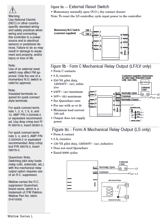
LF/LV Form C mechanical relay (single pole double throw) 8A/240V AC (resistive load), 250VA (inductive load, 120/240V AC), 30V DC (maximum) contactor coil, solenoid valve, alarm light, etc. Inductive load requires parallel RC suppressor (Watlow P/N 08040147-0000) 100000 cycles (at rated current)
LS Form A mechanical relay (single pole single throw) 8A/240V AC (resistive load), 120VA (inductive load, 120/240V AC) is only used to cut off high-risk loads (such as heating tube power supply), without the need for RC suppressors for 6000 cycles (at rated current)
Output logic: Under normal conditions, the NO (normally open) contact of LF/LV is closed and the NC (normally closed) contact is open; After triggering the restriction condition, the output is locked, the NO contact is disconnected, and the NC contact is closed (cutting off the load power or triggering an alarm).
(2) Protection function
Temperature limit:
High temperature limit (full series): Protection is triggered when the temperature exceeds the set point.
Low temperature limit (LF/LV only): Protection is triggered when the temperature is below the set point (such as freezing of refrigeration equipment).
Sensor fault protection:
Sensor open circuit: triggers output lockout, displays fault code [Er; In] (only LV is displayed).
Sensor short circuit: When the thermocouple is short circuited, the ambient temperature is displayed, and when the RTD is short circuited, the low range value is displayed, both triggering protection.
LS series additional protection:
Dual sensor deviation monitoring: When the temperature difference between the two sensors exceeds 20 ° C, protection is triggered to prevent single sensor failure.
Environmental over temperature protection: When the internal temperature of the controller exceeds 85 ° C, the protection is triggered to avoid self failure.
Reset method:
LF/LV: Supports panel RESET button reset or external momentary normally open switch reset (terminal 9), reset requires temperature to drop below "set point hysteresis".
LS: Only supports power-off reset (power must be disconnected for ≥ 3 seconds) to prevent accidental operation and release protection, in compliance with safety level design.
Core functions and operation guide
1. Core functional features
(1) Independent security logic
It has no electrical connection with the main controller, independent power supply, independent sampling, and independent output. Even if the main controller loses control (such as output adhesion), it can still monitor the temperature and cut off the load through its own sensors, avoiding "common cause faults".
Setpoint locking: LF/LS setpoints cannot be modified on site, LV needs to press the SET button to adjust, to prevent unauthorized personnel from operating them incorrectly.
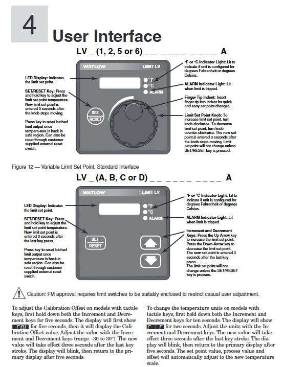
(2) Operation interface functions (LV series only)
The LV series offers two versions of the operating interface, adapted to different operating habits:
Rotary encoder version (Figure 12):
Display screen: 4-digit LED displays the set point, the ° F/° C indicator light displays the current unit, and the ALARM indicator light is on to trigger protection.
Operation: Press the SET/RESET button and rotate the encoder to adjust the set point. After the encoder stops for 3 seconds, it will automatically save; After triggering the protection, press the RESET button to reset (if the temperature meets the standard).
Button version (Figure 13):
Buttons: UP (increase), DOWN (decrease), SET/RESET (confirm/reset). Press the SET button for 3 seconds to enter adjustment mode, UP/DOWN button to modify the set point, no operation saved for 3 seconds.
Advanced function: Press and hold the UP+DOWN button for 5 seconds to enter calibration offset (-30~30 ° C); Press and hold for 10 seconds to switch between ° F/° C units, and the set point and measured value will be automatically converted after switching.
(3) Fault diagnosis and status indication
Solution to the meaning of series fault codes/indicator lights
LV [Er; In] sensor input fault (open/short circuit). Check the sensor wiring and replace the sensor
LS two LED alternate flashing dual sensors temperature difference>20 ° C or polarity reversed check sensor polarity, adjust installation position to ensure temperature difference ≤ 20 ° C
LS Limit LED flashes, Range LED lights up, temperature does not drop to reset threshold, wait for temperature to drop below "set point hysteresis", or power off to reset
The full range of ALARM LEDs are constantly on, triggering temperature limit protection to investigate the cause of overheating (such as heating tube adhesion), and ensuring temperature safety before resetting
2. Key configuration points
(1) Set point configuration
LF series: The set point is specified by the ordering model, such as "0120" in "LFC4JW0120AAAA" indicating a set point of 120 ° F. It is necessary to ensure that the set point is within the sensor range (such as 0-750 ° C for J-type thermocouples).
LV series: on-site adjustment, the steps are as follows:
Press the SET button for 3 seconds, and the display screen will flash to enter adjustment mode.
Rotary encoder (or press UP/DOWN key) to modify the set point, the range should be within the "low limit set point - high limit set point" (customized when ordering).
Stop the operation for 3 seconds, the display screen stops flashing, and the set point is saved.
LS series: The set point and hysteresis loop are specified by the ordering model, for example, in "LSF4HW0900220AA", "0900" represents the set point of 900 ° F and "220" represents the hysteresis loop of 20 ° F, which cannot be modified on site.
(2) Temperature unit configuration
LF/LS: Unit specified by ordering model (such as J-type thermocouple with "J" in ° C and "H" in ° F), cannot be switched on site.
LV: The button version supports unit switching, steps:
Press and hold the UP+DOWN key for 10 seconds, and the display screen will show "F" and "C".
Press the UP key to switch to ° F, and press the DOWN key to switch to ° C.
No operation for 3 seconds, the unit takes effect, and the set point and measured value are automatically converted (such as 100 ° C → 212 ° F).
(3) External reset configuration (LF/LV only)
Wiring: Connect an external momentary normally open switch (such as a button) to terminal 9 (RESET) and the common terminal (COM).
Function: After triggering the protection, press the external switch (or panel RESET button), and if the temperature has dropped to the reset threshold, output a reset; If the temperature does not meet the standard, resetting will be ineffective to avoid danger relief.
Installation and wiring specifications
1. Installation process (taking panel installation and rail installation as examples)
(1) 1/8 DIN panel installation (LV series, IP65 protection)
Preparation for Drilling: Drill holes on the panel in a size of 72.4mm × 72.4mm, with smooth edges and no burrs, and a panel thickness of 1.52-3.18mm.
Sealing gasket inspection: Confirm that the rubber sealing gasket on the front of the controller is not twisted and fits snugly into the groove of the housing to ensure IP65 protection.
Embedded controller: Insert the controller from the front of the panel, with the sealing gasket completely covering the edge of the opening without any offset.
Fixed bracket: Install the bracket from the back of the panel, ensuring that the bracket buckle is aligned with the ridge of the controller housing, press the bracket tightly against the panel, and lock the buckle with your thumb (both side buckles need to be locked at the same time to avoid uneven force causing sealing failure).
Check installation: Gently shake the controller without looseness; The front of the panel has no protrusions/indentations, and the sealing gasket has no compression deformation.
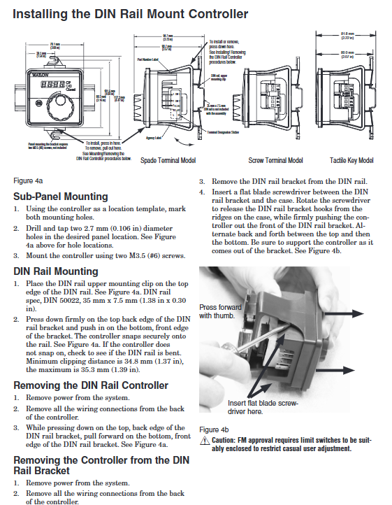
(2) DIN rail installation (LF series)
Rail preparation: Confirm that the DIN rail complies with DIN 50022 standard (35mm × 7.5mm), and is installed on a flat surface inside the cabinet, away from heat sources such as frequency converters and contactors.
Buckle installation: Insert the upper hook of the controller into the upper edge of the guide rail, press the lower part of the controller until the lower buckle "clicks" to lock onto the lower edge of the guide rail (if unable to lock, check if the guide rail is bent, adjust and retry).
Disassembly method: Press the release button on the upper part of the controller, while pulling the lower part forward to disengage the buckle from the guide rail, and remove the controller (disconnect the power and wiring before disassembly).
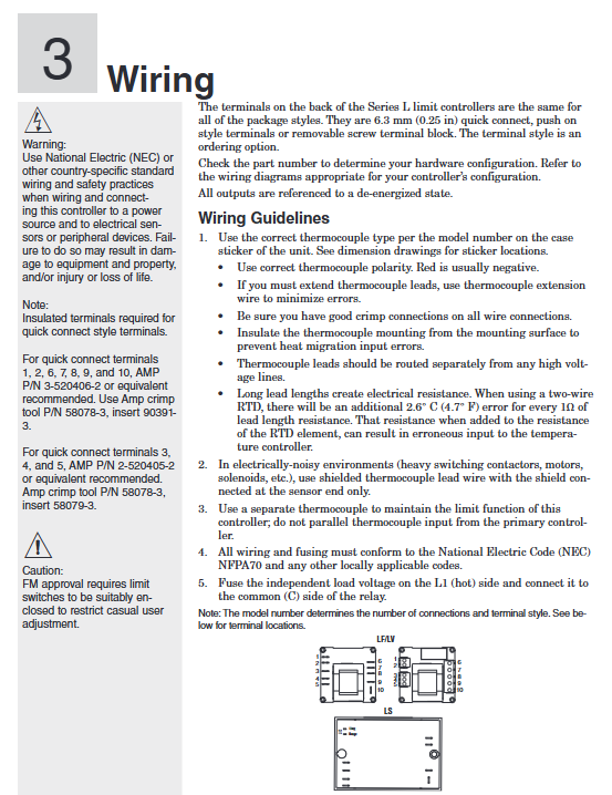
2. Wiring specifications and safety requirements
(1) Preparation before wiring
Power off confirmation: Before wiring, all relevant power sources must be disconnected, and a multimeter must be used to confirm that there is no voltage to avoid electric shock.
Wire selection:
Power wire: 12-18 AWG copper wire, current carrying capacity ≥ controller maximum current (LF/LV ≤ 0.5A, LS ≤ 0.1A).
Sensor wires: Thermocouples use the same type of compensating wire (such as JX-HS-FF for J-type), RTDs use 3-core shielded wire (20-24 AWG), and the shielding layer is only grounded at the sensor end.
Output wire: Depending on the load current, an additional RC suppressor (Watlow P/N 08040147-0000) needs to be connected in series for inductive loads.
(2) Core wiring example (LF/LV single circuit protection)
Power wiring: L1 (live wire) is connected to terminal 1, L2 (neutral wire) is connected to terminal 2, and a 2A slow melting fuse (250V) is connected in series. The live wire end needs to be connected to a circuit breaker (for easy power-off maintenance).
Sensor wiring (J-type thermocouple): The positive (non red) terminal of the thermocouple is connected to terminal 5, and the negative (red) terminal is connected to terminal 10. The extension wire needs to be a J-type compensating wire to avoid copper wires.
Output wiring: Relay COM terminal is connected to terminal 6, NO terminal is connected to one end of the contactor coil, and the other end of the coil is connected to L2; NC terminal is backup (can be connected to an alarm light), inductive load (contactor coil) is connected in parallel with an RC suppressor (between terminal 6 and NO terminal).
External reset wiring: One end of the external button is connected to terminal 9, and the other end is connected to terminal 6 (COM end). The button is of the instantaneous and constant on type (such as Schneider XB2-BA31).
(3) LS series dual sensor wiring
Power wiring: Connect L1 to terminal 1, L2 to terminal 2, and connect 2A slow melting fuses in series.
Dual sensor wiring (K-type thermocouple): Sensor 1 is connected to positive terminal 5 and negative terminal 10; The positive terminal of sensor 2 is connected to terminal 4, and the negative terminal is connected to terminal 9. The installation positions of the two sensors should be close (temperature difference ≤ 20 ° C).
Output wiring: The relay COM terminal is connected to terminal 6, and the NO terminal is connected to the heating tube power circuit. After triggering the protection, the NO terminal is disconnected, cutting off the heating tube power supply.
(4) Safety wiring requirements
Electrical isolation: Sensor cables, power cables, and output cables need to be wired separately (with a spacing of ≥ 10cm) to avoid electromagnetic interference; The grounding terminal of the controller (if any) needs to be connected to a protective ground (grounding resistance ≤ 4 Ω).
Installation in hazardous areas: Explosion proof junction boxes and armored cables are required for Class 1 Div. 2 hazardous areas, with terminal tightening torque ≥ 0.56 Nm, and live plug and unplug wiring is prohibited.
Anti misoperation wiring: strictly follow the terminal label for wiring, and do not reverse the positive and negative terminals of the power supply or the sensor (otherwise abnormal display or failure to trigger protection).
3. Analysis of Typical System Wiring Diagram (Industrial Oven Protection)
System composition: The main controller (Watlow Series CV) controls the temperature of the oven, while the LF series serves as redundant protection to prevent overheating caused by main controller failure.
Wiring logic:
The LF sensor and the main controller sensor are installed at different positions in the oven to avoid single point failures.
The LF output is connected in series with the main contactor coil circuit, and the main controller output is also connected in series with this circuit, forming a "double safety".
After triggering the LF protection, the contactor coil loses power, cutting off the power supply to the heating tube, and the ALARM light is on, requiring manual reset (or external button reset).
Troubleshooting and Maintenance
1. Common faults and solutions
Possible causes of malfunction, troubleshooting steps, and solutions
No display/action, ALARM light not on. 1. Power not connected or circuit breaker tripped
2. The fuse is blown
3. The safety interlock switch is not closed (such as the oven door switch). 1. Use a multimeter to measure the voltage at terminal 1/2 and confirm that the power supply is normal
2. Check the fuse of the power circuit. If it is blown, check if there is a short circuit in the load
3. Check the status of the interlock switch to ensure it is closed. 1. Connect the power supply and reset the circuit breaker
2. Replace the 2A slow melting fuse and repair the load short circuit
3. Close the interlock switch (such as closing the oven door)
Abnormal temperature reading (high/low), ALARM light triggered incorrectly. 1. Sensor type configuration error (e.g. actual J type, K type selected when ordering)
2. Reverse the wiring of the sensor
3. Excessive wire resistance (RTD)
4. The ambient temperature exceeds 70 ° C. 1. Check the ordered model and actual sensor type to ensure consistency
2. Swap the positive and negative poles of the sensor and observe if the reading returns to normal
3. Measure the resistance of the RTD wire. If it is greater than 1 Ω, replace the thick wire or shorten the length
4. Measure the temperature inside the cabinet. If it exceeds the temperature limit, add a ventilation fan. 1. If the configuration is incorrect, it needs to be recalibrated at the factory
2. Correct the polarity of the sensor wiring
3. Replace RTD wires with 20 AWG or more
4. Improve cabinet ventilation and reduce ambient temperature
Unable to reset after triggering protection. 1. The temperature has not dropped below the "set point hysteresis"
2. LS series power on reset
3. External reset switch fault: 1. Measure the actual temperature and confirm if it meets the standard (if the set point is 100 ° C and the hysteresis is 3 ° C, it needs to be lowered to below 97 ° C)
2. LS series needs to be disconnected from the power supply for ≥ 3 seconds and then powered on again
3. Measure the reset switch with a multimeter to see if it conducts when pressed. 1. Wait for the temperature to drop to a safe range
2. Perform power-off reset (LS series)
3. Replace the faulty reset switch
Two LEDs flashing alternately (LS series) 1. Dual sensor temperature difference>20 ° C
2. Sensor polarity reversed
3. One of the sensors is faulty. 1. Measure the actual temperature of the two sensors and confirm if the temperature difference exceeds 20 ° C
2. Swap the positive and negative poles of one of the sensors and observe if the flashing stops
3. Short circuit the two sensor terminals separately and observe if they still flash. 1. Adjust the sensor installation position to reduce the temperature difference
2. Correct the polarity of the sensor
3. Replace the faulty sensor
2. Daily maintenance and calibration
(1) Regular maintenance (monthly)
Appearance inspection: The panel is not damaged, the LED indicator light is normal (power light on, ALARM light off), the wiring terminals are not loose or oxidized, and the sealing gasket is not aged.
Functional testing:
Simulate overheating: Heat the sensor with a standard temperature source and confirm that the ALARM light will turn on and output an action when the temperature reaches the set point.
Reset test: After the temperature drops to a safe range, press the RESET button (or power off) to confirm the output reset and ALARM light off.
Cleaning: Wipe the panel with a dry cloth to remove terminal dust. Do not use corrosive cleaning agents such as alcohol and acetone.
(2) Annual calibration
Calibration tools: standard temperature source (such as FLUKE 9170), high-precision multimeter (such as FLUKE 8846A), standard resistance box (for RTD calibration).
Thermocouple calibration steps:
Set the standard temperature source to the midpoint of the sensor range (such as J-type thermocouple 300 ° C), and record the controller display value after stabilization.
If the error is greater than ± 1%, the LV series can adjust the calibration offset through the panel (long press the UP+DOWN button for 5 seconds to enter calibration mode and adjust to the standard value); The LF/LS series needs to be returned to the factory for calibration.
RTD calibration steps:
Use a standard resistance box to output 119.4 Ω (corresponding to 100 ° C, DIN curve), and record the displayed value of the controller.
When the error exceeds the limit, adjust the RTD wire compensation (3-wire system) or return to the factory for calibration.
(3) Fault record
Suggest establishing maintenance logs to record the time, symptoms, troubleshooting process, and solutions of faults, with a focus on recording:
Determine the frequency of sensor failures (such as open circuits and short circuits) and determine whether to replace the sensor or improve the installation environment.
The triggering reasons for over temperature protection, such as frequent adhesion of heating tubes, require early replacement of aging components.
Typical application scenarios
1. Industrial oven temperature protection (LF series)
Requirement: The oven main controller (such as PLC+temperature module) controls heating and requires redundant protection to prevent the main controller output from sticking and causing overheating (such as setting a point of 180 ° C and triggering protection for overheating at 200 ° C).
Configuration: LF series fixed set point of 200 ° C, K-type thermocouple (range 0-300 ° C), potting module installation, output connected in series to the heating tube contactor coil circuit, triggering to cut off the coil power supply.
Advantages: No user interface, preventing unauthorized modifications; The sealing structure is suitable for high temperature environments near the oven and has IP65 protection against dust.
2. Food baking oven protection (LV series)
Requirement: The baking oven needs to adjust the temperature frequently (such as baking bread at 180 ° C and cake at 160 ° C), and the maximum temperature should be limited to 220 ° C to prevent the batter from burning.
Configuration: LV series adjustable set point (range 100-220 ° C), J-type thermocouple, 1/8 DIN panel installation (IP65 protection), rotary encoder to adjust set point, output triggers alarm light and contactor trip.
Advantages: Quick on-site adjustment of set points, with anti misoperation design; IP65 protection is suitable for cleaning and spraying in food processing environments.
3. Heating protection for coating production line (LS series)
Requirement: If the heating tube in the coating and drying section loses control, it may cause a fire and requires high safety level protection. The set point is 120 ° C, dual sensor redundancy, and only power-off reset.
Configuration: LS series double K-type thermocouple, set point 120 ° C, hysteresis loop 5 ° C, DIN rail installation, output directly cuts off the power supply of the heating tube, triggering protection when the temperature difference between the two sensors is greater than 20 ° C.
Advantages: Dual sensor redundancy+power-off reset, in compliance with safety standards; Form A output is only used to cut off high-risk loads and has high reliability.
- YOKOGAWA
- Reliance
- ADVANCED
- SEW
- ProSoft
- WATLOW
- Kongsberg
- FANUC
- VSD
- DCS
- PLC
- man-machine
- Covid-19
- Energy and Gender
- Energy Access
- Renewable Integration
- Energy Subsidies
- Energy and Water
- Net zero emission
- Energy Security
- Critical Minerals
- A-B
- petroleum
- Mine scale
- Sewage treatment
- cement
- architecture
- Industrial information
- New energy
- Automobile market
- electricity
- Construction site
- HIMA
- ABB
- Rockwell
- Schneider Modicon
- Siemens
- xYCOM
- Yaskawa
- Woodward
- BOSCH Rexroth
- MOOG
- General Electric
- American NI
- Rolls-Royce
- CTI
- Honeywell
- EMERSON
- MAN
- GE
- TRICONEX
- Control Wave
- ALSTOM
- AMAT
- STUDER
- KONGSBERG
- MOTOROLA
- DANAHER MOTION
- Bentley
- Galil
- EATON
- MOLEX
- Triconex
- DEIF
- B&W
- ZYGO
- Aerotech
- DANFOSS
- KOLLMORGEN
- Beijer
- Endress+Hauser
- schneider
- Foxboro
- KB
- REXROTH
- YAMAHA
- Johnson
- Westinghouse
- WAGO
- TOSHIBA
- TEKTRONIX
- BENDER
- BMCM
- SMC
- HITACHI
- HIRSCHMANN
- XP POWER
- Baldor
- Meggitt
- SHINKAWA
- Other Brands
- UniOP
- KUKA
- IBA
- Beckhoff
-
ADLINK CPCI-6860A - 51-31310-OB10 industrial motherboard CompactPCI SBC
-
ADLINK AmITX-SL-G-H110 - 51-7A104-0A30 Mini-ITX Industrial Motherboard
-
ADLINK PXI-2005-003 - CPCI Industrial PC Data Acquisition Card Multi-Function DAQ
-
ADLINK DININ-814M - 51-14032-0A3D SCSI-100P cable connection Interface Terminal Board
-
ADLINK CPCI-3920NA/C2D15/M1G - 3U CompactPCI Intel Core 2 Duo Single Board Computer
-
ADLINK PCIE-8560 - 51-18014-0A20 Communication Card High Speed DAQ
-
ADLINK PCI-C154+ - Motion Control Card 4-axis Motion Controller Board
-
ADLINK PCI-RTV24 - image capture card Analog Video Frame Grabber
-
ADLINK NuPRO-842LV/P - 51-41360-0B30 Industrial Motherboard CPU Board
-
ADLINK cBP-3208/3208R - CPCI Board 3U 8-Slot CompactPCI Backplane
-
ADLINK PCI-8164 - 4-Axis Motion Controller PCI Card 51-12406-0A40
-
ADLINK PCIe-GIE64+ - 4-CH GigE Vision PoE+ Frame Grabber Video Capture Card
-
ADLINK CPCI-6860 / 6860A - CompactPCI Dual Xeon Single Board Computer
-
ADLINK IEC-915GV - REV 1.1 Industrial motherboard CPU Board
-
ADLINK ND-6520 - Technology RS-232 to RS-422RS-485 Converter NuDAM Module
-
ADLINK RTV-24 / PCI-MP4S - 51-12519-1C30 4-Channel Real Time Video Capture Board
-
ADLINK cPCI-6910 / cPCI-6910AM/M1G - cPCI-6910AM/DXL16/M1G/S80G(G)-3120 BOARD CompactPCI SBC
-
ADLINK NUPRO-A40H - Linghua 51-41807-1A30 Industrial Control Computer Motherboard
-
ADLINK USB-3488A - USB to GPIB INTERFACE USB-3488A(G) Controller Module
-
ADLINK PCI-8134A - motion control card 4-Axis Controller Card
-
ADLINK PCI-7432 - Board 32-Channel input / 32-output Isolated Digital I/O PCI Card
-
ADLINK PCI-8134A - 51-12421-0A10 motion controller card tested
-
ADLINK LPCIe-7230 - 32 CH Isolated Input/output Card 2 Interrupts Low Profile PCIe
-
ADLINK NuPRO-E340 - industrial computer motherboard 51-47807-0A30 PICMG 1.3 SHB
-
ADLINK PCI-7434 - High-speed Digital Acquisition Card 64-CH Isolated DO Card
-
ADLINK NuPRO-E330 - 51-41805-0A20 Indsutrial Board SHB Single Board Computer
-
ADLINK PCI-7248 - OPTO-22 48 CHANNEL DIO DIGITAL TTL/DTL I/O 51-12006-0A40 GP
-
ADLINK PCI-8134 - Motion control card 4-Axis Controller Card
-
ADLINK AMP-208C - Movimiento Control Tarjeta 51-12420-1A20 W/Expansión & Breakout
-
ADLINK PCI-8164 - 51-12406-0A40 PCB Board 4-Axis Motion Controller Card
-
ADLINK DIN-68Y-SGII / DIN-68M-J3A - Terminal Board Connector Interface Block
-
ADLINK PCIe-7432 - Technology 51-18402-0A10 PCIe Card With High Input Range
-
ADLINK PCI-8144 / PCI-8144N - Motion control card 4-Axis Stepper Controller Card
-
ADLINK HSL-HUB3/REPEATER - HIGH SPEED LINK EXTENSION MODULES Distributed Hub Module
-
ADLINK ND-6017 - Data Logging + Acquisition 8CH A/D input Mod NuDAM Module
-
ADLINK LPCIe-7250 - data acquisition card Low Profile 8-CH Relay Output Card
-
ADLINK PCI-7432 - I/O card 64-CH Isolated Digital Input Output PCI Card
-
ADLINK IMB-M43H - industrial control computer motherboard Q87 Chip Micro-ATX
-
ADLINK MP-C154 - Motion control Card 4-Axis Motion Controller Board
-
ADLINK PCI-RTV24 - image capture card Video Frame Grabber Card
-
ADLINK PCI-7250 - 8-CH Relay Output & 8-CH Isolated DI Card
-
ADLINK PCI-6308V - 8-CH 12-Bit Isolated Analog Output PCI Card PCB-I-E-1148=6EX2
-
ADLINK PCI-7248 - capture card 48-CH Opto-22 Compatible DIO Card
-
ADLINK HSL-AI16A02-M-VV - Analog Input Output Distributed Module
-
ADLINK NuPRO-A301 - Rev:1.4 NUPRO-A301 PICMG Full-Size Single Board Computer
-
ADLINK PCI-6208V-GL - 8-CH Voltage Analog Output PCI Card
-
ADLINK PCI-8134A - 51-12421-0A10 4-Axis Motion Controller Card
-
ADLINK MNET-S23 - TECHNOLOGY MNET S23 - SERVO DRIVER CONTROL MODULE
-
ADLINK M-342 - ATX I3 I5 I7 Q67 Industrial Motherboard
-
ADLINK NUPRO-780 - Industrial Motherboard CPU Board PICMG SBC
-
ADLINK MP-C154 / MP-C152 - 4-Axis Motion Control Card Pulse-Train Controller
-
ADLINK NuPRO-935A/LV10B0 - Motherboard 51-41802-0A10 GP w/RAM Industrial Control Board
-
ADLINK MP-C154 - Motion control card 4-Axis Motion Controller Mainboard
-
ADLINK PCI-7250 - PCI Acquisition Card 8-CH Relay Output Isolated DI Card
-
ADLINK ACL-7124 - Technology Inc.24 DIO Card Digital Input Output Card
-
ADLINK PCI-8554 A2 - Timer/Counter Data Acquisition Card
-
ADLINK DIN-825-GP4 - Terminal Block Interface Board Breakout Module
-
ADLINK NuPR0-761 - REV:1.1 Industrial motherboard Full-Size PICMG SBC
-
ADLINK MXE-1401/M8G (G) - Matrix Fanless Embedded Computer Industrial PC
-
ADLINK HSL-DI16DO16-UD-NN - Digital 16 Channel I/O Mod Distributed I/O Module
-
ADLINK ND6520 - NUDAM INTELLIGENT DA&C MODULE RS232-RS-422/RS485 CONVERTOR
-
ADLINK NUPRO-761 - REV:1.1 Industrial Motherboard CPU Board
-
ADLINK AMP-208C - Motion Control Card 51-12420-1A20 DSP-based 8-axis
-
ADLINK NuPRO-A301REV 1.4 - with packaging industrial computer motherboard PICMG SBC
-
ADLINK PCM-9112+ - 51-12300-0A2 industrial motherboard Multi-Function DAQ PC/104 Module
-
ADLINK PCM-7250+ - 8-CH Relay Outputs & 8-CH Isolated DI Module PC/104
-
ADLINK PCI-RTV24 - Image capture card Analog Video Frame Grabber
-
ADLINK PCI-8134 - Motion Controller PCI Card 4-Axis Controller Board
-
ADLINK PCI-7432 - Isolated Digital I/O PCI Card
-
ADLINK PCI-8554 A2 - acquisition card Timer/Counter Card
-
ADLINK PCI-8132 - Rev.A2 2-Axis Servo & Stepper Motion Controller Card
-
ADLINK PCI-8132 - Data Acquisition card 2-Axis Motion Controller Card
-
ADLINK EBP-13E4 - 51-46703-0A30 Industrial Backplane Board Passive Backplane
-
ADLINK PCI-800L - Electronic Card Interface Controller Card
-
ADLINK PCIe-GIE72 - 51-18531-0A10 PCB Board GigE Vision Frame Grabber
-
ADLINK DAQ-2010(G)-OOBO - Simultaneous-Sampling Multi-Function DAQ Card
-
ADLINK PCI-9112 - REV.B1 Multifunction DAQ Card Data Acquisition Card
-
ADLINK PCI-7230 - 51-12003-DA60 32-CH Isolated Digital I/O Card
-
ADLINK PCI-7432 - Data Acquisition Card Isolated Digital I/O PCI Card
-
ADLINK ETX-AT-N270-18/LXE - 51-71111-0A20 ETX CPU Module Motherboard
-
ADLINK HSL-DI32-UD-N - DIGITAL INPUT 32 POINTS MODULE Distributed I/O
-
ADLINK AMP-204C - Motion Control card DSP-Based 4-Axis Advanced Controller
-
ADLINK MNET-4XMOG-0050 - Four-axis Motion Controller Distributed Motion Module
-
ADLINK AMP-204C - Motion control card DSP-Based 4-Axis Pulse-Train Controller
-
ADLINK PCI-7442 - Switch card 64-Channel Datalogging & Acquisition Card
-
ADLINK M-302 - Industrial control motherboard ATX PC Board
-
ADLINK NUPRO-852 / NUPRO-852LV - Industrial motherboard Single Board Computer
-
ADLINK PCI-8134 - REV.B1. 4-Axis Motion Controller Card
-
ADLINK PCI-GIE62 + - 51-18502-0A20 2-CH GigE Vision Frame Grabber PoE Card
-
ADLINK PCI-MPG24 - 51-12523-0B20 MPEG4 Card Video Compression Hardware
-
ADLINK HSL-TB32-M-DIN - 32-CH I/O TERMINAL W/ HSL-AI16AO2-M-VV MODULE
-
ADLINK PCI-M114-GL - PCB Ver 2.1 Motion Controller Axis Card
-
ADLINK IMB-M40H - SYM76996H61 motherboard Industrial Computer Mainboard
-
ADLINK NUPRO-A40H - 51-41807-1A20 industrial control motherboard H61 Chip
-
ADLINK PCI-M114-GL - Axis Card Data Acquisition Card PCB VER2.2 Motion Controller
-
ADLINK PCI-8134 - Motion Controller PCI Card 4-Axis Controller Board
-
ADLINK PCI-8102 - Motion control card 2-Axis Servo & Stepper Controller
-
ADLINK NuPRO-841REV:3.0 - motherboard Industrial Control PC Board
-
ADLINK HSL-TB32-U-DIN REV A1 - Breakout Terminal Board Field I/O Module
-
ADLINK AMP-204C - Motion Control card DSP-Based 4-Axis Pulse-Train Controller
-
ADLINK NUPRO-A40H - 51-41807-1A20 industrial control motherboard H61 PC Board
-
ADLINK PCI-6308A / PCI-6308V - 51-12202-0A50 Isolated Analog Output Card
-
ADLINK AMP-204C - DSP-Based 4-Axis Advanced Pulse-Train Motion Controller
-
ADLINK PCI-7434 - Technology 64-Channel Isolated Digital I/O PCI Cards
-
ADLINK CPCI-6840 / CPCI-6840V / PM16/M1G-12G0 - CompactPCI Single Board Computer CPU Module
-
ADLINK PCIE-GIE74 - Motherboard Video Capture Card 51-18531-0A10 Frame Grabber
-
ADLINK NuPRO-E330 - industrial computer equipment motherboard Control Mainboard
-
ADLINK AMP-208C / 51-12420-1A20 - Motion Control Card W/ Expansion & Breakout Board
-
ADLINK HPCI-14S12U - industrial computer baseboard Passive Backplane 14 Slots
-
ADLINK PCI-8164 - 4-Axis Motion Controller PCI Card W/ 1x Cable, 1x Breakout Box
-
ADLINK PCIe-RTV24 - 51-18016-0A20 Image Acquisition Video Capture Card
-
ADLINK M-342 - 5 PCI ATX Motherboard Industrial PC Mainboard
-
ADLINK PCI-FIW64 - 4/2 Channel IEEE1394B Image Capture Card FireWire Frame Grabber
-
ADLINK PCI-7432 - digital IO card 64-CH Isolated Digital Input Output Card
-
ADLINK 51-12001-0C20 - Circuit Board PCI-7200 Data Acquisition Controller Card
-
ADLINK PXI-3920 - PXI 3U cPCI Industrial Controller Embedded System CPU Board
-
ADLINK NuPRO-841REV:2.0 - motherboard Industrial Control PC Board
-
ADLINK NuPro-E330 - 51-41805-0A20 PCB Industrial Control Computer Motherboard
-
ADLINK PCI-RTV24 - Image capture card Analog Video Frame Grabber
-
ADLINK PCI-7442 - Switch card 64-Channel Datalogging & Acquisition Card
-
ADLINK HPX-13S4 - device baseboard Passive Backplane Riser Card
-
ADLINK PCI-9112 REV A.1 - Multi Function DA&C Board Data Acquisition Card
-
ADLINK PCI-7248 - 51-12006-0A40 Card Control 48-CH Digital I/O Module
-
ADLINK CPCI-6860 / 6860A - motherboard CompactPCI Dual Xeon Single Board Computer
-
ADLINK DPAC-3020-11(G) - Embedded PC Automation Controller Machine Control Board
-
ADLINK NuPRO-841 REV:1.0 - industrial control motherboard CPU Board
-
ADLINK MNET-4XMOG-0050 - Four-axis Motion Controller MNET Motion Control Card
-
ADLINK ETX-AT-N270-18/LXE - 51-71111-0A20 ETX CPU Module Motherboard

K-JIANG

Add: Jimei North Road, Jimei District, Xiamen, Fujian, China
Tell:+86-15305925923