
K-WANG


Watlow Series F4P Series 1/4 DIN (96 × 96mm) Temperature/Process Controller
Watlow Series F4P Series 1/4 DIN (96 × 96mm) Temperature/Process Controller
Product basic information and positioning
1. Core positioning
Specially designed for industrial process control, it can be installed independently or integrated, providing measurement and control of temperature, pressure and other parameters, supporting single/multi loop linkage, adapting to bidirectional control scenarios such as heating and cooling, and possessing both basic control and advanced extended functions (such as cascade control and proportional control).
2. Basic specifications
Appearance and Installation: 96 × 96mm panel installation, thickness 97mm, with reserved panel openings of 92-93mm, vertical installation, supporting NEMA 4X/IP65 protection level (must be properly tightened and sealed).
Power supply requirements: 100-240V AC (50/60Hz) or 24-28V AC/DC, maximum power consumption of 39VA, Class 2/SELV certified power supply, supporting Semi F47-0200 voltage drop standard.
Environmental adaptability: working temperature 0-65 ° C, storage temperature -40-70 ° C, 0-90% RH (non condensing), compliant with UL, CE, EN 61010 and other safety certifications, some models support Class 1 Div. 2 hazardous areas.
Warranty and Support: 3-year warranty (non misuse scenario), technical support can be obtained through phone or email, and returns need to apply for an RMA number in advance.
Core functions and technical features
1. Input/output capability
(1) Input type and specifications
Input type, quantity, key parameters, applicable scenarios
Universal analog input 1 channel (advanced version 2-3 channels) supports thermocouple (11 types including J/K/T), RTD (2-3 wire system, 100 Ω platinum), process signal (0-10V, 4-20mA, etc.), input impedance: voltage 20k Ω, current 100 Ω, temperature, pressure and other parameter acquisition
Four digital inputs support dry contact/DC voltage input (low state<2V, high state>3V), with a response frequency of 10Hz for external triggering and status feedback (such as door switches and limit signals)
(2) Output type and specifications
Output Type Quantity Key Parameters Applicable Scenarios
Control output 2-channel (1A/1B) optional relays (2A/250V AC), SSR (0.5A/24-253V AC), open collector (42V DC/0.5A), process output (4-20mA/0-10V) to drive heaters, refrigeration equipment, valves
Alarm output 2-channel mechanical relay (Form C, 2A/250V AC), supporting normally open/normally closed configuration fault alarm and emergency stop linkage
Resend output (optional) 1-2 channels of 4-20mA (maximum 800 Ω) or 0-10V (minimum 1k Ω) with an accuracy of ± 30 μ A/± 15mV signal to the recorder PLC
2. Control and calculation functions
(1) Basic control mode
Switch control: The device can be started and stopped by setting a threshold and hysteresis, and the hysteresis can be adjusted (1-9999 units) to avoid frequent switching.
PID control: supports proportional (P), proportional integral (PI), and proportional integral derivative (PID) regulation, stores 5 sets of PID parameters, and adapts to different operating conditions for switching.
Automatic tuning: Through 4 oscillation tests crossing the set point, the optimal PID parameters are automatically calculated, supporting local (internal loop) or global tuning.
Multi PID switching: can trigger 5 sets of PID parameter switching based on set points or process values, suitable for a wide range of operating conditions (such as different characteristics in high and low temperature ranges).
(2) Advanced control functions
Cascade Control (Advanced Version): Dual loop linkage, with the output of the external loop (such as process temperature) serving as the set point for the internal loop (such as heat source temperature), reducing overshoot and hysteresis.
Proportional/Differential Control (Advanced Version): Proportional control supports proportional operation between process values and reference values, while differential control adjusts output based on parameter change rate.
Valve positioning control (advanced version): Feedback valve position through potentiometer, dual output control valve switch, support dead zone and hysteresis adjustment, compatible with three-way valves.
Slope control: Set the rate of temperature/parameter change (1-999 units/minute/hour) to avoid process fluctuations caused by rapid changes.
3. Alarm and safety functions
Alarm types: Support process alarm (fixed threshold), deviation alarm (relative to the set point), rate alarm (parameter changes too quickly), with 2 independent alarm outputs.
Alarm configuration: High and low alarm thresholds, hysteresis (1-9999 units), lockout/automatic reset, and startup mute can be set to avoid false alarms during the startup phase.
Fault protection: supports sensor open circuit detection, automatically switches to manual mode (output 0%) after triggering, and displays fault codes; Optional independent limit controller linkage to prevent overheating/overpressure risks.
4. Communication and Expansion
Communication protocol: Supports EIA-232/EIA-485 bus, Modbus RTU protocol, baud rate 9600/19200/38400bps, addresses 1-247, maximum transmission distance 1200 meters (EIA-485).
Scalability: The advanced version supports 2-3 analog inputs, remote set point inputs, dual loop cascading, and can trigger set point switching, mode switching, and other functions through digital inputs.
Operation and Configuration Guide
1. Menu and Navigation
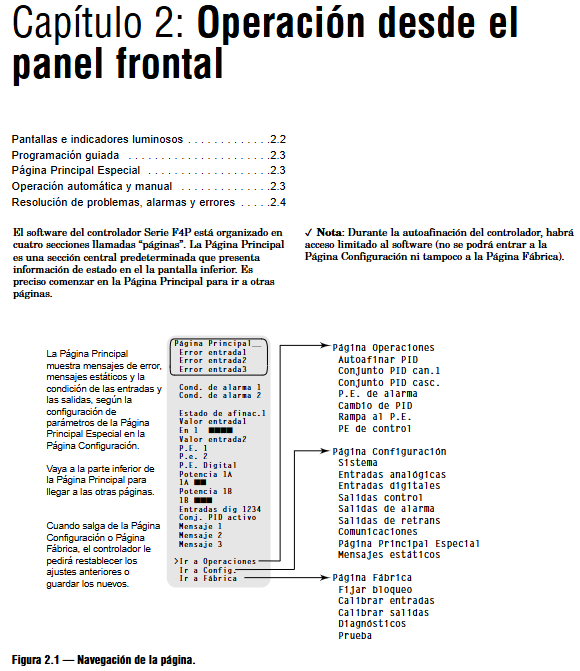
Core page: divided into 4 levels of pages - homepage (status display), operation page (PID tuning, alarm setting), configuration page (input/output, system parameters), factory page (calibration, safety settings).
Operation mode: 4 directional keys (up and down adjustment/left and right navigation)+automatic/manual switch key+information key (parameter description), supports guided configuration, intuitive operation logic.
Display function: 5-segment red LED main display (process value)+green LCD auxiliary display (status, menu), supporting 16 custom status display items (such as output power, PID group).
2. Key configuration process
(1) Basic configuration steps
System configuration: Select temperature units (° F/° C), PID unit system (SI/Imperial), and power failure response mode.
Input configuration: Select sensor type, range, filtering time (0-60 seconds), linearization compensation (10 point calibration).
Output configuration: Set the control output type (heating/cooling), cycle (0.1-60 seconds), and process output range (e.g. 4-20mA corresponds to 0-100%).
Alarm configuration: Select the alarm type, threshold, and linkage output logic (normally open/normally closed).
PID tuning: Start automatic tuning or manually adjust the proportional band, integration time, and differentiation time.
(2) Advanced configuration
Cascade control: Configure the range and PID parameters of the external loop (process parameters) and internal loop (heat source parameters), and the set point of the internal loop is determined by the output of the external loop.
Remote Setpoints: Switch 3 sets of remote setpoints through analog input (such as 4-20mA) or digital input, suitable for multiple process scenarios.
Security settings: 4-level permission control (full access/read-only/password protection/hidden), supporting 4-digit password setting and modification to prevent unauthorized operations.
3. Calibration and maintenance
Input calibration: for thermocouples RTD、 Process signals can be calibrated using standard signal sources (such as 0-10V, 4-20mA) for two-point/multi-point calibration, supporting the restoration of factory calibration values.
Output calibration: Adjust the accuracy of control output and retransmission output to ensure that the signal is consistent with the set value (e.g. 4mA corresponds to 0%, 20mA corresponds to 100%).
Self diagnosis: supports hardware fault detection (such as RAM and Flash faults), module recognition, parameter verification, and intuitive display of fault codes.
Installation and Wiring Guide
1. Installation process
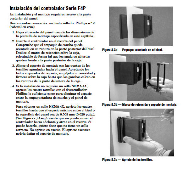
Panel drilling: Drill holes according to the size of 92-93mm, clean the installation surface, and ensure that there are no oil stains or burrs.
Controller fixing: Insert the controller into the panel, install the fixing bracket and sealing gasket, and tighten the screws (NEMA 4X protection requires ensuring that the sealing gasket is compressed evenly with a gap of ≤ 0.508mm).
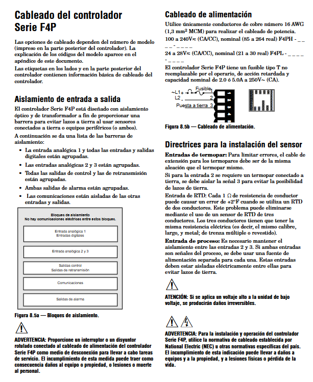
Wiring specifications: Sensor cables and power cables should be wired separately (with a spacing of ≥ 10cm), and shielded twisted pair cables should be used for analog signals. The shielding layer should be grounded at one end (on the control room side).
2. Wiring requirements
(1) Core terminal definition
Power terminal: 100-240V AC connected to L/N, 24V DC connected to+/-, requires series connection of slow melting fuses (2A/250V).
Analog input terminals: thermocouple connected+/-, RTD (3-wire system) connected S1/S2/S3, process signal (4-20mA) connected+/- (requires external power supply or loop power supply).
Control output terminals: Relay output connected to COM/NO/NC, SSR output connected to control terminal, process output connected to signal+/-.
Communication terminals: EIA-485 is connected to T+/T -/GND, EIA-232 is connected to TX/RX/GND, and supports daisy chain topology (with 120 Ω terminal resistors connected at the beginning and end).
(2) Safe wiring
Installation in hazardous areas: Explosion proof junction boxes and armored cables are required for Class 1 Div. 2 models, and live plug and unplug wiring is prohibited.
Inductive load protection: When driving relays and solenoid valves, parallel RC suppressors (Watlow 0804-0147-0000) or freewheeling diodes are required to prevent voltage spikes from damaging the module.
Electrical isolation: Input, output, and communication circuits are isolated from each other to avoid grounding loops (grounding resistance ≤ 4 Ω).
3. Typical application wiring
Single loop temperature control: thermocouple/RTD connected to analog input, control output to drive heater, alarm output linked to buzzer/indicator light, communication interface connected to PLC for remote monitoring.
Cascade control system: The external loop (process temperature) input is connected to a temperature sensor, and the output controls the set point of the internal loop (heat source). The internal loop input is connected to a heat source temperature sensor, and the output drives the heating equipment.
Troubleshooting and Maintenance
1. Common faults and solutions
Possible causes and solutions for the fault phenomenon
No display/power light not on, abnormal power supply, blown fuse, reversed wiring. Measure the power supply voltage, replace the 2A slow melting fuse, and check the positive and negative wiring
Abnormal sensor reading, incorrect sensor type configuration, loose wiring, shielding interference. Check the sensor model and configuration, re tighten the wiring, and check the grounding of the shielding layer
Communication failure: baud rate/address mismatch, reversed wiring, terminal resistance not connected. Unified communication parameters, correct T+/T - polarity, and add 120 Ω resistors to the first and last modules
Alarm does not trigger threshold setting error, alarm function is not enabled, hysteresis is too large, reset alarm threshold, enable alarm output, reduce hysteresis (such as changing from 5 ℃ to 1 ℃)
Output unresponsive output type configuration error, load overload, relay/SSR damage. Verify output configuration, check load impedance, and replace damaged output components
2. Daily maintenance
Regular inspection: Check the terminal fastening, wiring integrity, display screen status every month, and remove panel dust (avoid using corrosive cleaning agents).
Calibration cycle: It is recommended to calibrate the input and output accuracy once a year, and for scenarios with large process fluctuations, it can be shortened to 6 months.
Parameter backup: configure parameters through software backup to avoid reconfiguration after failure; Record key parameters (such as PID group, alarm threshold) for easy maintenance.
Typical application scenarios
Industrial furnace temperature control: Collecting furnace temperature through thermocouples, adjusting heating power through PID, linking alarm output to prevent overheating, and implementing slope control to achieve slow heating and avoid workpiece deformation.
Refrigeration system control: Dual output controls the compressor (refrigeration) and heater (insulation) separately, deviation alarm monitors temperature fluctuations, and cascade control adapts to the temperature linkage of the condenser and evaporator.
Chemical pressure control: Process input is connected to a pressure sensor (4-20mA), proportional control is used to adjust valve opening, rate alarm is used to prevent pressure fluctuations, and remote set points support multi process pressure switching.
Valve positioning control: feedback valve position through potentiometer, dual output control valve switch, dead zone adjustment to avoid frequent actions, suitable for precise fluid flow control.
- YOKOGAWA
- Reliance
- ADVANCED
- SEW
- ProSoft
- WATLOW
- Kongsberg
- FANUC
- VSD
- DCS
- PLC
- man-machine
- Covid-19
- Energy and Gender
- Energy Access
- Renewable Integration
- Energy Subsidies
- Energy and Water
- Net zero emission
- Energy Security
- Critical Minerals
- A-B
- petroleum
- Mine scale
- Sewage treatment
- cement
- architecture
- Industrial information
- New energy
- Automobile market
- electricity
- Construction site
- HIMA
- ABB
- Rockwell
- Schneider Modicon
- Siemens
- xYCOM
- Yaskawa
- Woodward
- BOSCH Rexroth
- MOOG
- General Electric
- American NI
- Rolls-Royce
- CTI
- Honeywell
- EMERSON
- MAN
- GE
- TRICONEX
- Control Wave
- ALSTOM
- AMAT
- STUDER
- KONGSBERG
- MOTOROLA
- DANAHER MOTION
- Bentley
- Galil
- EATON
- MOLEX
- Triconex
- DEIF
- B&W
- ZYGO
- Aerotech
- DANFOSS
- KOLLMORGEN
- Beijer
- Endress+Hauser
- schneider
- Foxboro
- KB
- REXROTH
- YAMAHA
- Johnson
- Westinghouse
- WAGO
- TOSHIBA
- TEKTRONIX
- BENDER
- BMCM
- SMC
- HITACHI
- HIRSCHMANN
- XP POWER
- Baldor
- Meggitt
- SHINKAWA
- Other Brands
- UniOP
- KUKA
- IBA
- Beckhoff
-
Basler Electric DECS-250-CN1SN1N Automatic Voltage Regulator for Generator Excitation Control
-
ADLINK CPCI-6860A - 51-31310-OB10 industrial motherboard CompactPCI SBC
-
ADLINK AmITX-SL-G-H110 - 51-7A104-0A30 Mini-ITX Industrial Motherboard
-
ADLINK PXI-2005-003 - CPCI Industrial PC Data Acquisition Card Multi-Function DAQ
-
ADLINK DININ-814M - 51-14032-0A3D SCSI-100P cable connection Interface Terminal Board
-
ADLINK CPCI-3920NA/C2D15/M1G - 3U CompactPCI Intel Core 2 Duo Single Board Computer
-
ADLINK PCIE-8560 - 51-18014-0A20 Communication Card High Speed DAQ
-
ADLINK PCI-C154+ - Motion Control Card 4-axis Motion Controller Board
-
ADLINK PCI-RTV24 - image capture card Analog Video Frame Grabber
-
ADLINK NuPRO-842LV/P - 51-41360-0B30 Industrial Motherboard CPU Board
-
ADLINK cBP-3208/3208R - CPCI Board 3U 8-Slot CompactPCI Backplane
-
ADLINK PCI-8164 - 4-Axis Motion Controller PCI Card 51-12406-0A40
-
ADLINK PCIe-GIE64+ - 4-CH GigE Vision PoE+ Frame Grabber Video Capture Card
-
ADLINK CPCI-6860 / 6860A - CompactPCI Dual Xeon Single Board Computer
-
ADLINK IEC-915GV - REV 1.1 Industrial motherboard CPU Board
-
ADLINK ND-6520 - Technology RS-232 to RS-422RS-485 Converter NuDAM Module
-
ADLINK RTV-24 / PCI-MP4S - 51-12519-1C30 4-Channel Real Time Video Capture Board
-
ADLINK cPCI-6910 / cPCI-6910AM/M1G - cPCI-6910AM/DXL16/M1G/S80G(G)-3120 BOARD CompactPCI SBC
-
ADLINK NUPRO-A40H - Linghua 51-41807-1A30 Industrial Control Computer Motherboard
-
ADLINK USB-3488A - USB to GPIB INTERFACE USB-3488A(G) Controller Module
-
ADLINK PCI-8134A - motion control card 4-Axis Controller Card
-
ADLINK PCI-7432 - Board 32-Channel input / 32-output Isolated Digital I/O PCI Card
-
ADLINK PCI-8134A - 51-12421-0A10 motion controller card tested
-
ADLINK LPCIe-7230 - 32 CH Isolated Input/output Card 2 Interrupts Low Profile PCIe
-
ADLINK NuPRO-E340 - industrial computer motherboard 51-47807-0A30 PICMG 1.3 SHB
-
ADLINK PCI-7434 - High-speed Digital Acquisition Card 64-CH Isolated DO Card
-
ADLINK NuPRO-E330 - 51-41805-0A20 Indsutrial Board SHB Single Board Computer
-
ADLINK PCI-7248 - OPTO-22 48 CHANNEL DIO DIGITAL TTL/DTL I/O 51-12006-0A40 GP
-
ADLINK PCI-8134 - Motion control card 4-Axis Controller Card
-
ADLINK AMP-208C - Movimiento Control Tarjeta 51-12420-1A20 W/Expansión & Breakout
-
ADLINK PCI-8164 - 51-12406-0A40 PCB Board 4-Axis Motion Controller Card
-
ADLINK DIN-68Y-SGII / DIN-68M-J3A - Terminal Board Connector Interface Block
-
ADLINK PCIe-7432 - Technology 51-18402-0A10 PCIe Card With High Input Range
-
ADLINK PCI-8144 / PCI-8144N - Motion control card 4-Axis Stepper Controller Card
-
ADLINK HSL-HUB3/REPEATER - HIGH SPEED LINK EXTENSION MODULES Distributed Hub Module
-
ADLINK ND-6017 - Data Logging + Acquisition 8CH A/D input Mod NuDAM Module
-
ADLINK LPCIe-7250 - data acquisition card Low Profile 8-CH Relay Output Card
-
ADLINK PCI-7432 - I/O card 64-CH Isolated Digital Input Output PCI Card
-
ADLINK IMB-M43H - industrial control computer motherboard Q87 Chip Micro-ATX
-
ADLINK MP-C154 - Motion control Card 4-Axis Motion Controller Board
-
ADLINK PCI-RTV24 - image capture card Video Frame Grabber Card
-
ADLINK PCI-7250 - 8-CH Relay Output & 8-CH Isolated DI Card
-
ADLINK PCI-6308V - 8-CH 12-Bit Isolated Analog Output PCI Card PCB-I-E-1148=6EX2
-
ADLINK PCI-7248 - capture card 48-CH Opto-22 Compatible DIO Card
-
ADLINK HSL-AI16A02-M-VV - Analog Input Output Distributed Module
-
ADLINK NuPRO-A301 - Rev:1.4 NUPRO-A301 PICMG Full-Size Single Board Computer
-
ADLINK PCI-6208V-GL - 8-CH Voltage Analog Output PCI Card
-
ADLINK PCI-8134A - 51-12421-0A10 4-Axis Motion Controller Card
-
ADLINK MNET-S23 - TECHNOLOGY MNET S23 - SERVO DRIVER CONTROL MODULE
-
ADLINK M-342 - ATX I3 I5 I7 Q67 Industrial Motherboard
-
ADLINK NUPRO-780 - Industrial Motherboard CPU Board PICMG SBC
-
ADLINK MP-C154 / MP-C152 - 4-Axis Motion Control Card Pulse-Train Controller
-
ADLINK NuPRO-935A/LV10B0 - Motherboard 51-41802-0A10 GP w/RAM Industrial Control Board
-
ADLINK MP-C154 - Motion control card 4-Axis Motion Controller Mainboard
-
ADLINK PCI-7250 - PCI Acquisition Card 8-CH Relay Output Isolated DI Card
-
ADLINK ACL-7124 - Technology Inc.24 DIO Card Digital Input Output Card
-
ADLINK PCI-8554 A2 - Timer/Counter Data Acquisition Card
-
ADLINK DIN-825-GP4 - Terminal Block Interface Board Breakout Module
-
ADLINK NuPR0-761 - REV:1.1 Industrial motherboard Full-Size PICMG SBC
-
ADLINK MXE-1401/M8G (G) - Matrix Fanless Embedded Computer Industrial PC
-
ADLINK HSL-DI16DO16-UD-NN - Digital 16 Channel I/O Mod Distributed I/O Module
-
ADLINK ND6520 - NUDAM INTELLIGENT DA&C MODULE RS232-RS-422/RS485 CONVERTOR
-
ADLINK NUPRO-761 - REV:1.1 Industrial Motherboard CPU Board
-
ADLINK AMP-208C - Motion Control Card 51-12420-1A20 DSP-based 8-axis
-
ADLINK NuPRO-A301REV 1.4 - with packaging industrial computer motherboard PICMG SBC
-
ADLINK PCM-9112+ - 51-12300-0A2 industrial motherboard Multi-Function DAQ PC/104 Module
-
ADLINK PCM-7250+ - 8-CH Relay Outputs & 8-CH Isolated DI Module PC/104
-
ADLINK PCI-RTV24 - Image capture card Analog Video Frame Grabber
-
ADLINK PCI-8134 - Motion Controller PCI Card 4-Axis Controller Board
-
ADLINK PCI-7432 - Isolated Digital I/O PCI Card
-
ADLINK PCI-8554 A2 - acquisition card Timer/Counter Card
-
ADLINK PCI-8132 - Rev.A2 2-Axis Servo & Stepper Motion Controller Card
-
ADLINK PCI-8132 - Data Acquisition card 2-Axis Motion Controller Card
-
ADLINK EBP-13E4 - 51-46703-0A30 Industrial Backplane Board Passive Backplane
-
ADLINK PCI-800L - Electronic Card Interface Controller Card
-
ADLINK PCIe-GIE72 - 51-18531-0A10 PCB Board GigE Vision Frame Grabber
-
ADLINK DAQ-2010(G)-OOBO - Simultaneous-Sampling Multi-Function DAQ Card
-
ADLINK PCI-9112 - REV.B1 Multifunction DAQ Card Data Acquisition Card
-
ADLINK PCI-7230 - 51-12003-DA60 32-CH Isolated Digital I/O Card
-
ADLINK PCI-7432 - Data Acquisition Card Isolated Digital I/O PCI Card
-
ADLINK ETX-AT-N270-18/LXE - 51-71111-0A20 ETX CPU Module Motherboard
-
ADLINK HSL-DI32-UD-N - DIGITAL INPUT 32 POINTS MODULE Distributed I/O
-
ADLINK AMP-204C - Motion Control card DSP-Based 4-Axis Advanced Controller
-
ADLINK MNET-4XMOG-0050 - Four-axis Motion Controller Distributed Motion Module
-
ADLINK AMP-204C - Motion control card DSP-Based 4-Axis Pulse-Train Controller
-
ADLINK PCI-7442 - Switch card 64-Channel Datalogging & Acquisition Card
-
ADLINK M-302 - Industrial control motherboard ATX PC Board
-
ADLINK NUPRO-852 / NUPRO-852LV - Industrial motherboard Single Board Computer
-
ADLINK PCI-8134 - REV.B1. 4-Axis Motion Controller Card
-
ADLINK PCI-GIE62 + - 51-18502-0A20 2-CH GigE Vision Frame Grabber PoE Card
-
ADLINK PCI-MPG24 - 51-12523-0B20 MPEG4 Card Video Compression Hardware
-
ADLINK HSL-TB32-M-DIN - 32-CH I/O TERMINAL W/ HSL-AI16AO2-M-VV MODULE
-
ADLINK PCI-M114-GL - PCB Ver 2.1 Motion Controller Axis Card
-
ADLINK IMB-M40H - SYM76996H61 motherboard Industrial Computer Mainboard
-
ADLINK NUPRO-A40H - 51-41807-1A20 industrial control motherboard H61 Chip
-
ADLINK PCI-M114-GL - Axis Card Data Acquisition Card PCB VER2.2 Motion Controller
-
ADLINK PCI-8134 - Motion Controller PCI Card 4-Axis Controller Board
-
ADLINK PCI-8102 - Motion control card 2-Axis Servo & Stepper Controller
-
ADLINK NuPRO-841REV:3.0 - motherboard Industrial Control PC Board
-
ADLINK HSL-TB32-U-DIN REV A1 - Breakout Terminal Board Field I/O Module
-
ADLINK AMP-204C - Motion Control card DSP-Based 4-Axis Pulse-Train Controller
-
ADLINK NUPRO-A40H - 51-41807-1A20 industrial control motherboard H61 PC Board
-
ADLINK PCI-6308A / PCI-6308V - 51-12202-0A50 Isolated Analog Output Card
-
ADLINK AMP-204C - DSP-Based 4-Axis Advanced Pulse-Train Motion Controller
-
ADLINK PCI-7434 - Technology 64-Channel Isolated Digital I/O PCI Cards
-
ADLINK CPCI-6840 / CPCI-6840V / PM16/M1G-12G0 - CompactPCI Single Board Computer CPU Module
-
ADLINK PCIE-GIE74 - Motherboard Video Capture Card 51-18531-0A10 Frame Grabber
-
ADLINK NuPRO-E330 - industrial computer equipment motherboard Control Mainboard
-
ADLINK AMP-208C / 51-12420-1A20 - Motion Control Card W/ Expansion & Breakout Board
-
ADLINK HPCI-14S12U - industrial computer baseboard Passive Backplane 14 Slots
-
ADLINK PCI-8164 - 4-Axis Motion Controller PCI Card W/ 1x Cable, 1x Breakout Box
-
ADLINK PCIe-RTV24 - 51-18016-0A20 Image Acquisition Video Capture Card
-
ADLINK M-342 - 5 PCI ATX Motherboard Industrial PC Mainboard
-
ADLINK PCI-FIW64 - 4/2 Channel IEEE1394B Image Capture Card FireWire Frame Grabber
-
ADLINK PCI-7432 - digital IO card 64-CH Isolated Digital Input Output Card
-
ADLINK 51-12001-0C20 - Circuit Board PCI-7200 Data Acquisition Controller Card
-
ADLINK PXI-3920 - PXI 3U cPCI Industrial Controller Embedded System CPU Board
-
ADLINK NuPRO-841REV:2.0 - motherboard Industrial Control PC Board
-
ADLINK NuPro-E330 - 51-41805-0A20 PCB Industrial Control Computer Motherboard
-
ADLINK PCI-RTV24 - Image capture card Analog Video Frame Grabber
-
ADLINK PCI-7442 - Switch card 64-Channel Datalogging & Acquisition Card
-
ADLINK HPX-13S4 - device baseboard Passive Backplane Riser Card
-
ADLINK PCI-9112 REV A.1 - Multi Function DA&C Board Data Acquisition Card
-
ADLINK PCI-7248 - 51-12006-0A40 Card Control 48-CH Digital I/O Module
-
ADLINK CPCI-6860 / 6860A - motherboard CompactPCI Dual Xeon Single Board Computer
-
ADLINK DPAC-3020-11(G) - Embedded PC Automation Controller Machine Control Board
-
ADLINK NuPRO-841 REV:1.0 - industrial control motherboard CPU Board
-
ADLINK MNET-4XMOG-0050 - Four-axis Motion Controller MNET Motion Control Card

K-JIANG

Add: Jimei North Road, Jimei District, Xiamen, Fujian, China
Tell:+86-15305925923