
K-WANG


Honeywell System 57 5704 Control System
Honeywell System 57 5704 Control System
Product positioning and core functions
The Honeywell System 57 5704 control system is a microprocessor controlled device used for industrial gas detection, belonging to the System 57 product family. Its core function is to monitor industrial gas detectors installed on site, achieve multi-channel gas concentration monitoring, alarm triggering, and system management. It is suitable for indoor non hazardous areas and should not be exposed to rainwater or moisture. It is also not designed for use in hazardous areas. The system supports catalytic and 4-20mA input types of gas sensors, with flexible alarm configuration, remote control, and self diagnostic capabilities. Calibration, maintenance, and parameter settings can be performed through engineering cards, and it is also compatible with extended functions such as Modbus communication and event printing.
System composition and hardware specifications
(1) Core hardware module
Four Channel Control Card
Type differentiation: divided into catalytic input type (model 05704-A-0144) and 4-20mA input type (model 05704-A-0145). The former supports catalytic gas sensors and provides constant current drive (adjustable from 90-315mA), while the latter is suitable for 4-20mA circuit power supply sensors with a measurement range of 0-25mA.
Display and indication: Equipped with four LCD displays (25 segment analog bar, 4-digit digital display, 4-digit message display, icon area), 4 channel LEDs (CHL1-CHL4) and 1 Attention (ATTN) LED, which can distinguish A1/A2/A3 alarm, STEL/LTEL alarm, fault, suppression and other states by LED flashing frequency/color.
Core parameters: Initial accuracy ± 1%, alarm set point resolution 1% of full range, electronic drift<± 3%/6 months, operating voltage 18-32V DC, catalytic type maximum power consumption 12.8W, 4-20mA type maximum power consumption 8.3W.
relay interface module
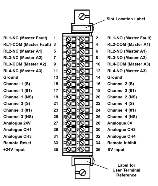
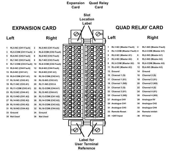
Quad Relay Interface Card (model 05704-A-0121): Provides 4 Single Pole Double Throw (SPCO) relays, supporting latch/non latch, power on/off action modes, and rated relay contacts 5A@110 /250V AC or 32V DC, supporting interface connection between sensors and control cards, with a maximum power consumption of 1.7W.
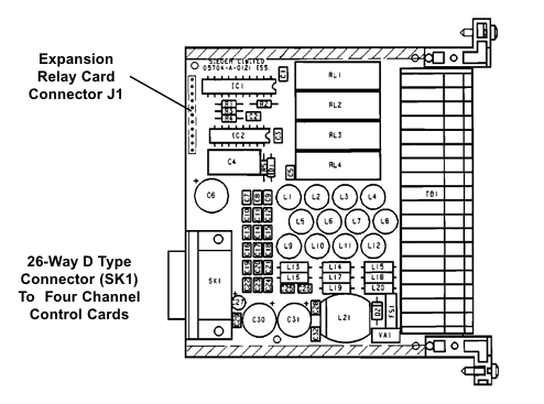
Relay Interface Assembly (model 05704-A-0131): It consists of four relay interface cards and an extended relay card, including 12 SPCO relays and 4 Single Pole Single Throw (SPST) relays, occupying 2 card slots, with a maximum power consumption of 6.5W, suitable for scenarios that require more relay outputs.
Engineering Card (Model 05701-A-0361)
Functional positioning: The core module for system configuration, calibration, and maintenance, equipped with green power LED, red unlock LED, as well as directional keys (up/down), confirm/cancel keys, function keys (BEAD mA, ALARMS, ZERO, SPAN, etc.).
Core Capability: Supports sensor bridge current regulation, alarm threshold setting and relay testing, zero/range calibration, system clock setting, can be configured and data printed through RS232 interface connected to printer or PC, with a power consumption of approximately 1.5W.
DC Input Card (Model 05701-A-0325)
Function: Provides a system DC power supply interface, supports two independent power inputs (such as main power and backup battery), has diode isolation and 10A anti surge fuse, supports 2.5mm ² (14 AWG) wire terminals, and operates at a voltage of 18-32V DC.
other modules
Analog output module: divided into current absorption type (04200-A-0145) and current source type (04200-A-0146), output range 0-20mA or 4-20mA software optional, linearity ± 2% of full range, supporting external power supply of 18-40V.
Expansion module: including event printing module (05701-A-0314), Modbus interface module (RS232 type 05701-A-0313, RS485/422 type 05701-A-0312), alarm update module (05701-A-0309), etc., used to expand communication and alarm functions.
(2) System rack and cabinet
Rack: available in full 19 inch and half 19 inch widths, supporting front or rear wiring, including engineering cards, DC input cards, and interconnecting cables (front wiring type), made of galvanized steel, with M5 grounding terminal bolts, weighing approximately 287.6-217.6g including modules (depending on model).
Cabinet: divided into 8 channels (model 05701-A-0452) and 16 channels (model 05701-A-0451), made of low carbon steel, RAL 7015 dark gray, equipped with knockout cable sealing sleeves (8 channels include 2 M25, 8 M20, etc.), weighing 10kg for 8 channels and 13.5kg for 16 channels.
(3) Power supply unit
AC-DC power supply unit: divided into 8 channels (model 05701-A-0406) and 16 channels (model 05701-A-0405), input 85-264V AC (47-440Hz) or 110-340V DC, output 24V DC ± 10%, can be upgraded by adding a 50W switch module (model 05701-A-0440) (maximum 100W for 8 channels, maximum 200W for 16 channels), with overload protection (triggered by 105% rated load, automatic recovery), maximum leakage current 0.75mA/50W module.
Installation and wiring requirements
(1) Environment and Location
For indoor use only, avoid heat sources, moisture, and physical damage. The ambient temperature is -5-55 ℃ (ATEX certification system is 0-55 ℃), the humidity is 0-90% RH (no condensation), and the altitude is ≤ 2000m.
The installation of sensors should follow the characteristics of gas density (installation height for gas sensors lighter than air, installation height for sensors heavier than air), avoid areas where airflow is obstructed, quiet corners, and near heat sources, and be easy to maintain.
(2) Wiring and Connection
Sensor wiring: It is necessary to use cables with grounding and external shielding to avoid parallel interference sources such as AC power lines and motors. The maximum length of the cable depends on the type of sensor and the cross-sectional area of the wire (for example, when using 2.5mm ² wire for catalytic sensors, the maximum length is 2500m, and when using 2.5mm ² wire for 4-20mA sensors, the maximum length is 16000m). The shielding layer is only grounded at the cabinet end.
Power and relay wiring: The rated current of the power cable should be greater than the maximum load. If the relay cable is connected to an AC power source, a 5A fuse is required. The DC input card and relay interface card terminals support 2.5mm ² wires. When wiring, the power should be disconnected to avoid short circuits.
(3) Power configuration
The total power consumption of the system needs to be calculated through the "power budget table", depending on the sensor type, number of channels, and module configuration; When there are more than 8 catalytic control cards, it is recommended to supply power separately through the four relay interface card to avoid the backplane current exceeding the 8A limit.
Supports dual input of main power supply and backup battery, with diode isolation achieved through a DC input card. The backup battery needs to be compatible with 18-32V DC specifications.
Operation and maintenance process
(1) Basic operation (without engineering key)
Control card reset and selection: Short press the RESET/SET button to reset inactive alarms and clear peak display; Long press and hold for 1.5 seconds to select the control card, then use the up and down keys on the engineering card to select the channel; Press and hold for 5 seconds to perform an extended reset (clear maximum/minimum readings, reset STEL/LTEL timer).
Basic functions of the engineering card: It can view the catalytic sensor bridge current (BEAD mA key), alarm threshold (ALARMS key), sensor signal (SIGNAL key), and system clock (CLOCK key). Calibration, suppression, and other operations cannot be performed without a key, and the selection will be automatically canceled after 30 seconds of timeout.
(2) Engineering operation (requires inserting the engineering key to unlock)
Channel suppression (INHIBIT key): After selecting a channel, press the INHIBIT key to switch the suppression state. During suppression, the channel LED will remain amber and the relay will be locked in an inactive state to avoid false alarms during calibration or troubleshooting.
Calibration process
Zero calibration (ZERO key): Ensure that the sensor is in a gas free environment, press the ZERO key, wait for the signal to stabilize (message displays "STANBLE"), and then press the confirm key. The system will automatically set the current signal to zero. If the signal exceeds the range, an error will be displayed.
Range calibration (SPAN key): Suitable for calibrated sensors, press the SPAN key to set the target range concentration, introduce the corresponding concentration standard gas, confirm after the signal is stable, and the system updates the range parameters; The new sensor requires the "1st SPAN" key to perform the first range calibration and record the initial sensitivity for lifespan monitoring.
Alarm and Relay Testing: Press the ALARMS key to set the A1/A2/A3/SETL/LTEL threshold. After switching to "TEST" mode, simulate gas concentration changes by pressing the up and down keys to verify whether the alarm LED and relay actions are normal. During testing, be sure to release the suppression to trigger the external relay.
(3) Maintenance and troubleshooting
Regular maintenance: It is recommended to check the terminal fastening, LED status, sensor signal and alarm function every year. The catalytic sensor needs to be calibrated regularly (according to the sensor manual). When the sensitivity of the catalytic sensor drops below 50% of the initial value, the system displays "Lifetime Expired" and the sensor needs to be replaced.
Fault diagnosis: Identify the problem through the error codes displayed on the control card message (such as ER97 for EEPROM fault, ER87 for over range fault, ER83 for bridge current fault), and check the power supply, wiring, and sensor status using the "troubleshooting table". Hardware faults require replacement of the corresponding module.
Data recording: It can be connected to an RS232 printer through an engineering card, and long press the up and down keys to print single channel status or overall rack summary data, including sensor type, calibration date, alarm threshold, relay configuration, and other information.
Compliance and safety requirements
(1) Certification and Standards
Compliant with EN50054/57/58 (General Requirements and Performance for Combustible Gas Detection), EN50271 (Software and Digital Technology), EMC Directive 89/336/EEC (EN50270:1999), Low Voltage Directive 73/23/EEC (EN 61010-1), ATEX certification based on EC Type Examination Certificate BVS 04 ATEX G 001 X, suitable for Zone 2 hazardous areas (requiring tested enclosures).
(2) Safety operation standards
Installation and maintenance should be carried out by professionals, and wiring should be operated after power failure to avoid equipment damage caused by incorrect sensor wiring; When used in hazardous areas, it is necessary to comply with the installation standard EN 60079-14 to ensure the enclosure protection level and explosion-proof requirements; The data read by Modbus is only used for visualization or recording and cannot be used for safety related control to avoid Modbus write operations.
Ordering and Accessories
Core module ordering models: Control card, relay interface card, engineering card, DC input card, etc. The core module models are clear, and the power unit, cabinet, and rack need to be selected according to the number of channels and installation requirements (such as 8-channel cabinet 05701-A-0452, 16 channel power supply 05701-A-0405).
Optional attachments: including blank panel (05701-A-0365), engineering key kit (05701-A-0550), interconnect cable (05704-C-0160), liquid tight connector kit, etc. Expansion modules such as Modbus interface and event printing module need to be ordered separately.
- YOKOGAWA
- Reliance
- ADVANCED
- SEW
- ProSoft
- WATLOW
- Kongsberg
- FANUC
- VSD
- DCS
- PLC
- man-machine
- Covid-19
- Energy and Gender
- Energy Access
- Renewable Integration
- Energy Subsidies
- Energy and Water
- Net zero emission
- Energy Security
- Critical Minerals
- A-B
- petroleum
- Mine scale
- Sewage treatment
- cement
- architecture
- Industrial information
- New energy
- Automobile market
- electricity
- Construction site
- HIMA
- ABB
- Rockwell
- Schneider Modicon
- Siemens
- xYCOM
- Yaskawa
- Woodward
- BOSCH Rexroth
- MOOG
- General Electric
- American NI
- Rolls-Royce
- CTI
- Honeywell
- EMERSON
- MAN
- GE
- TRICONEX
- Control Wave
- ALSTOM
- AMAT
- STUDER
- KONGSBERG
- MOTOROLA
- DANAHER MOTION
- Bentley
- Galil
- EATON
- MOLEX
- Triconex
- DEIF
- B&W
- ZYGO
- Aerotech
- DANFOSS
- KOLLMORGEN
- Beijer
- Endress+Hauser
- schneider
- Foxboro
- KB
- REXROTH
- YAMAHA
- Johnson
- Westinghouse
- WAGO
- TOSHIBA
- TEKTRONIX
- BENDER
- BMCM
- SMC
- HITACHI
- HIRSCHMANN
- XP POWER
- Baldor
- Meggitt
- SHINKAWA
- Other Brands
- UniOP
- KUKA
- IBA
- Beckhoff
- ADLINK
-
ADLINK HPCI-14S12U - Industrial Control Backplane 12PCI Backplane PCI-14S Passive Backplane
-
ADLINK PCIe-GIE74C - image acquisition card 4-CH GigE Vision PoE+ Frame Grabber
-
ADLINK PCI-8164 - control card 4-Axis Advanced Motion Controller Board
-
ADLINK PCIe-U304 - 4 Port USB3 PCIe Frame Grabbers USB Screw Hole Card
-
ADLINK PCI-9112 - Multi-Function Data Acquisition Card DAQ Card
-
ADLINK PCI-7432 - 51-12013-0A50 4-CH Isolated Numérique I/O PCI Cartes Digital I/O Card
-
ADLINK PCA-6106P3-0C1 REV.C1 - backplane 6-Slot Passive Backplane Board
-
ADLINK PCI-7224 - 24-CH Opto-Isolated Digital I/O PCI Board
-
ADLINK CPCI-7433R(G) - Digital Input Board Rear I/O CompactPCI Card
-
ADLINK EBP-13E4 - 51-46703-0A30 Industrial PC Backplane Passive Backplane
-
ADLINK PCIE-HDV62 - Image acquisition card High Definition Video Frame Grabber
-
ADLINK EBP-13E4 - 51-46703-0A30 Industrial Backplane Board Passive Backplane
-
ADLINK 90111-B1 / CPCI-6770 - PCB CPU MODULE CompactPCI Single Board Computer
-
ADLINK PCI-7248 - DATA ACQUISITION PCI CARD 48-CH Parallel Digital I/O Board
-
ADLINK PCI-7230 - 51-12003-0a50 board PCI7230 32-CH Isolated Digital I/O Card
-
ADLINK PCI2A000CB - 51-20000-0B30 Multi-Function DAQ Card Baseboard
-
ADLINK PCI-8134-005 - 4-Axis Motion Controller Card
-
ADLINK PCI-7224 - 24-CH Opto-Isolated Digital I/O PCI Card
-
ADLINK PCI-7434 - 64-CH Isolated Digital Output Card
-
ADLINK PCI-8132 - motion control card 2-Axis Servo & Stepper Controller
-
ADLINK PCI-8134 - Motion Controller PCI Card 4-Axis Controller Board
-
ADLINK PCI-8164 - Motion Control Card 51-12406-0A40 4-Axis Controller
-
ADLINK 51-12001-0C20 - Circuit Board Data Acquisition Interface Module Hardware
-
ADLINK NuPR0-840 - industrial control motherboard Full-Size PICMG CPU Board
-
ADLINK PCI-7444 - 51-12023-0A10 card 128-CH Isolated Digital Output Board
-
ADLINK PCI-1612B - data acquisition card 4-Port RS-232/422/485 Serial Communication Card
-
ADLINK PCI-6208V 009 - 8/16-CH 16-Bit Analog Output Cards PCB-I-E-482=6BX3
-
ADLINK NUPRO-935A/LV - industrial control motherboard Full-Size PICMG SBC Board
-
ADLINK PCI-9114DG - Multi-Function DAQ Card Data Acquisition PCI Card
-
ADLINK ACL-7130 - Data acquisition card Isolated Digital I/O Board
-
ADLINK ABX-6300D-4E1-BP - board ABX6300D4E1BP Video Interface Expansion Card
-
ADLINK CPCI-6940 - CPCI-6940/D1539/M16-0(EA)-000E 6U CompactPCI Processor Board
-
ADLINK NuPRO-760 - industrial control motherboard Half-Size PICMG SBC CPU Board
-
ADLINK IMB-M42H (G)-0020 - industrial control motherboard LGA1155 Micro-ATX Mainboard
-
ADLINK RTV-24 / PCI-MP4S - 51-12519-1C30 4-Channel Real Time Video Capture Board
-
ADLINK PCI-8134 - 4-Axis Servo & Stepper Motion Controller Card
-
ADLINK MXC-6101D - V.PC000.002.ST.00 Box PC Configurable Embedded Computer
-
ADLINK PCI-8134A - 51-12421-0A10 Motion Control Card 4-Axis Controller Card
-
ADLINK DIN-100S / DIN-100SA1 - Technology SCSI-II TB 100-PIN Terminal Block Board
-
ADLINK DIN-812M001 / DIN812M001 - 51-14034-0A1 51140340A1 Terminal Module Breakout Interface
-
ADLINK PCI-8164 - Servo motion control 4-Axis Advanced Controller Card
-
ADLINK PCIe-GIE64 - Acquisition card GigE Vision PoE+ Frame Grabber
-
ADLINK M-302 - Industrial control motherboard ATX PC Board Mainboard
-
ADLINK PCI-8134 - Motion Controller PCI Card 4-Axis Controller Board
-
ADLINK PCI-RTV24 - Image capture card Analog Video Frame Grabber
-
ADLINK PCI-8102 - Motion control card 2-Axis Servo & Stepper Controller Board
-
ADLINK PCI-9112 REV.B1 - Card Multi-Function Data Acquisition Card
-
ADLINK HSI-DI32-M-N / HSL-TB32-M-DIN - Discrete I/O MODULE Distributed Automation Module System
-
ADLINK PCI-7296 - IO card REV.A3 96-CH Parallel Digital I/O Card
-
ADLINK DIN-814P-A4 / 814Y - terminal board Motion Control Interface Block
-
ADLINK DIN-814P-A4 - 51-14056-0A10 PCB-I-E-2736=ZA01 Screw Terminal Board Breakout
-
ADLINK M-322 - motherboard Industrial Control Computer Mainboard
-
ADLINK NUPRO-406 REV:B1 - industrial control motherboard Full-Size PICMG CPU Board
-
ADLINK AMP-204C - card DSP-Based 4-Axis Advanced Pulse-Train Controller
-
ADLINK HPCI14S REV.B1 - industrial computer baseboard 14-Slot Passive Backplane
-
ADLINK PCI-7250 - 8-CH Relay Output & 8-CH Isolated DI PCI Card
-
ADLINK EBP-13E2 - baseplate Passive Backplane Industrial Computer Chassis Board
-
ADLINK LPCI-3488A - PCI-GPIB card 51-12801-0A30 acquisition card IEEE-488 Interface Board
-
ADLINK PCI-6216V-GL - 51-12201-0C30 16-CH 16-Bit Voltage Analog Output Card
-
ADLINK ACL-8454 - 16-CH Isolated Digital I/O & 4-CH Counter Card
-
ADLINK HPCI-9S7U - backplane Passive Backplane Compatible with NuPRO-A301 852 841 842
-
ADLINK DAQ-2010-007 - Simultaneous-Sampling Multi-Function Data Acquisition Card
-
ADLINK MP-C154 - 51-64205-0A10 Motion Control Card 4-Axis Controller Board
-
ADLINK MXE-202/mSSD16B/WiFi-BT - Matrix Rugged I/O Platform Embedded Fanless Computer
-
ADLINK CM-920-R-17 - PC/104-Plus Single Board Computer Module Intel Celeron M
-
ADLINK PCI-7250 NSMP - 8-CH Relay Output & 8-CH Isolated DI Card
-
ADLINK PCI-8164 - 4-Axis Motion Controller PCI Card W/ Cable and Breakout Box
-
ADLINK EMX-100 - Ethernet-based 4-axis Motion Controllers Distributed Motion Module
-
ADLINK PCI-8134A - Press control card 4-Axis Motion Controller Board
-
ADLINK M-845EG REV:3.2 - industrial motherboard Pentium 4 Socket 478 Micro-ATX
-
ADLINK PCI-9114A Rev A2 DG - card High-Resolution Multi-Function Data Acquisition Board
-
ADLINK IEC-915GV - REV 1.1 Industrial motherboard Socket 478 CPU Board
-
ADLINK PCI-9111DG(G) - Data Acquisition Card Multi-Function DAQ Card
-
ADLINK HPCI-15S10 REV:B2 - Industrial computer base plate Passive Backplane Board
-
ADLINK NuPR0-840 / NuPR0-840DV - industrial control motherboard Full-size PICMG CPU Board
-
ADLINK RTV-24 / PCI-MP4S - 51-12519-1C30 4-Channel Real Time Video Capture Board
-
ADLINK NUPRO-780 - industrial control motherboard Pentium III Single Board Computer
-
ADLINK PCI-7296 - 0050 card 96-CH Opto-Isolated Parallel DIO Card Set
-
ADLINK NUPRO-780 - industrial control motherboard PICMG Full-Size SBC
-
ADLINK PCI-7248 - 51-12006-0A3 002 Pci 7248 48-CH Parallel Digital I/O Card
-
ADLINK cPCI-6626 - 6U CompactPCI 2.0 Blades i7-2710QE PCB-I-E-2570=9N41
-
ADLINK MXC-6322D(G) - Industrial Fanless Computer
-
ADLINK cPCI-8168-004 - CompactPci NulPC Motion Control Board 51-36402-0A3
-
ADLINK CPCI-7300[G] - COMPACTPCI Digital I/O Card Data Acquisition
-
ADLINK CPCI-6626/2710/M4G - COMPACTPCI COMPUTER BOARD
-
ADLINK cPCI-8168-009 - cPCI NulPC Motion Control Board
-
ADLINK cPCI-6626/2710/M4G - VME CPU Board Computer Board
-
ADLINK CPCI-R6200(G)-0040 - COMPACTPCI CONTROL BOARD
-
ADLINK CPCI-3840/PM18/M1G(G)-3650 - COMPACTPCI CPU Module Single Board Computer
-
ADLINK cPCI-7248 - 48-CH Opto-22 Compatible Digital I/O Module
-
ADLINK DLAP-211-JNX - NVIDIA Jetson Xavier NX Edge AI Inference Platform
-
ADLINK cPCI-3544 - Series 4-Port RS-422/485 Isolated Serial Communications Card
-
ADLINK CM1-86DX3 - PC/104 SBC Stanley Vortex86DX3 CPU 2GB Ram
-
ADLINK DLAP-211-JNX - NVIDIA Jetson Xavier NX Edge AI Inference Platform
-
ADLINK cPCI-3544 - Series 4-Port RS-422/485 Isolated Serial Communications Card
-
ADLINK CM1-86DX3 - PC/104 SBC Stanley Vortex86DX3 CPU 2GB Ram
-
ADLINK PCI-7433 - switch value acquisition card Isolated Digital Input Card
-
ADLINK PCI-9112 - 51-12252-0D20 Multi-Function Data Acquisition Card
-
ADLINK NUPRO-A301 REV:1.4 - industrial control motherboard PICMG Full-Size SBC
-
ADLINK 51-18502-0A10 - Frame Grabber Image Acquisition Interface Card
-
ADLINK PCI-7296 - 51-12009-0A50 PCB-I-E-925=6DX1 96-CH Parallel Digital I/O Board
-
ADLINK PCI-8132 GP A2 - Motion Control Card 2-Axis Servo & Stepper Controller
-
ADLINK PCI-7442 - switch quantity card data acquisition card 64-CH Isolated Card
-
ADLINK HPX-13S4 - baseboard PICMG 1.3 Passive Backplane Chassis Baseplate
-
ADLINK NuPRO-590 / NTC-567-ZM-F36 - Single Board Computer PCB-I-E-1853=9L21 Half-Size SBC
-
ADLINK PCIe-8332 - 16-axis plate Motion Control Hardware Card
-
ADLINK NuPRO-775 REV.B1 - motherboard Pentium 4 Full-Size PICMG SBC
-
ADLINK PXI-3920 - Embedded Controller 3U PXI cPCI System Intelligence Board
-
ADLINK PCI-8134 - driver card motion control card 4-Axis Controller Board
-
ADLINK HSL-DI32-M-N-011 / HSL-TB32-M-DIN - Digital Input & Base Module PLC Distributed I/O System
-
ADLINK PCI-6216V-206 / PCI-208V 009 - 16 CH 16bit analog output card
-
ADLINK NuPro-E330 - 51-41805-0A20 PCB Single Board Computer Host Board
-
ADLINK PCI-1622C - Card 8-Port RS-232/422/485 PCI Serial Communication Board
-
ADLINK PCIe-7432 - 51-18402-0A10 Carte PCIe Avec Plage D'Entrée Élevée Isolated DIO Card
-
ADLINK PCI-7250 - PCI Acquisition Card 8-CH Relay Output Isolated DI Card
-
ADLINK PCI-7230 - 32-CH Isolated Digital I/O Card
-
ADLINK PCI-8164 - PCB 4-Axis Motion Controller Card
-
ADLINK PCI-7854 - Collection card High-Speed Link Distributed Motion Controller
-
ADLINK NuPRO-935A/LV - industrial control computer motherboard Full-Size PICMG SBC
-
ADLINK IMB-M40H - motherboard IH61-AA4 1155 LGA1155 Micro-ATX Mainboard
-
ADLINK PCI-7248 - Linhua 51-12006-0A40 48-CH Parallel Digital I/O Card
-
ADLINK HPCI-14S12U - Linhua industrial computer baseboard Passive Backplane
-
ADLINK PCI-8132 Rev.A2 - 2-Axis Servo & Stepper Motion Controller Card
-
ADLINK ACL-8111 - ISA card Multi-Function DAQ Card
-
ADLINK ACL-8111 - ISA card Multi-Function Data Acquisition Board
-
ADLINK PCI-7200 REV.A3 - Digital I/O card 12MB/s High-Speed Parallel Digital I/O
-
ADLINK PCI-7296 REV.A3 - 96-CH High-Density Opto-Isolated DIO Card
-
ADLINK PCI-7434 - 64-CH Isolated Digital Output Card

K-JIANG

Add: Jimei North Road, Jimei District, Xiamen, Fujian, China
Tell:+86-15305925923