
K-WANG


GE Multilin 469 Motor Protection System
GE Multilin 469 Motor Protection System
Product positioning and core values
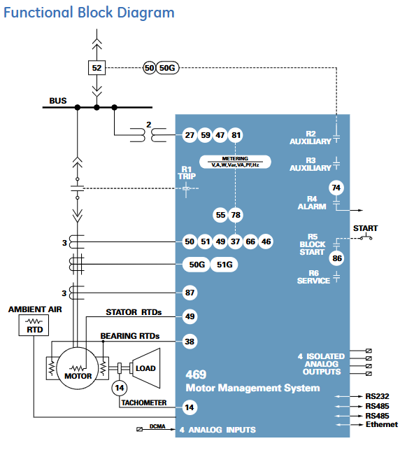
The GE Multilin 469 motor protection system belongs to the SR relay family and is an integrated protection and management device designed specifically for medium and high voltage, large and medium-sized motors. It adopts a pull-out structure, balancing cost-effectiveness and industry-leading flexibility. Its core positioning is to provide comprehensive protection, precise control, simplified configuration, and advanced communication functions for medium and large three-phase motors (including high inertia, dual speed, and step-down starting motors), suitable for safe operation and management of motors and driving equipment in industrial scenarios. It can adapt to different motor characteristics through customized overload curves, single CT differential protection, and other functions. At the same time, with the help of motor parameter auto configurator, multi communication protocol compatibility, and other features, deployment and operation costs can be reduced, and equipment availability can be improved.
Core functions and protective features
(1) Comprehensive motor protection function
Hot model protection (core protection mechanism)
Multidimensional thermal management: integrating six core elements: overload curve (standard/customized/voltage dependent), negative sequence current bias (compensating for additional rotor heating), cold and hot safety stagnation ratio (defining the steady-state thermal capacity utilization rate of the motor), cooling time constant (distinguishing the heat dissipation rate during operation/shutdown), startup suppression and emergency restart (preventing startup when the thermal capacity is insufficient), RTD bias (combined with stator RTD temperature correction thermal model), updating the thermal capacity utilization rate (TCU) every 0.1 seconds, accurately simulating the actual thermal state of the motor.
Overload Curve Characteristics: Provides 15 standard overload curves (multiplier 1-15). The voltage dependent curve is suitable for high inertia loads and can dynamically adjust the thermal overload curve during the acceleration phase according to the system voltage, avoiding motor overheating caused by acceleration time exceeding the safe dead time.
Fault and abnormal working condition protection
Electrical fault protection: covering stator differential protection (supporting 6 CT external summation or 3 flux balanced CT connection, distinguishing the tripping threshold for startup/operation status), short circuit protection (removing the DC component of fault current, supporting secondary tripping backup when the fault is not cleared), grounding fault protection (supporting zero sequence CT, high sensitivity CT, phase CT residual connection, dual tripping/alarm threshold).
Abnormal working condition protection: including mechanical jamming (detecting rotor stalling, locking during startup), acceleration time monitoring (preventing abnormal long acceleration process), undervoltage/overvoltage (independent threshold during motor startup/operation phase, supporting locking in case of VT fuse failure), underfrequency (adjustable from 20-60Hz), over torque (adjustable from 1.0-999999.9 Nm/ft lb, only induction motor alarm), current imbalance (detecting negative sequence current ratio, including phase failure detection algorithm, dual trip/alarm threshold), etc.
Temperature and hardware protection
RTD Temperature Monitoring: Supports 12 programmable RTD inputs (compatible with Platinum 100, Nickel 100/120, Copper 10, etc.) to monitor stator, bearing, and ambient temperature. Each RTD includes three levels of thresholds: alarm, high alarm, and trip. Supports RTD trip voting and open/short circuit fault alarm.
Other hardware protections: including reverse power (to prevent motor from generating electricity due to reverse dragging), underpower (to detect load loss), abnormal power factor (synchronous motor out of step detection), limit on starting times/starting intervals (to prevent excessive starting losses), etc.
(2) Control and configuration functions
Flexible control mode: supports dual speed motor protection (independent overload curve), voltage reduction start monitoring (transition current/time control), frequency conversion filtering (suitable for accurate acquisition of analog signals in VFD scenarios), analog input differential calculation (dual drive system application), trip coil monitoring, etc., to meet the control requirements of different starting modes and operating scenarios.
Simplified configuration tool: equipped with a motor parameter auto configurator, complete parameter settings through a 6-step guided operation; Support on-site firmware and parameter upgrades, with optional conformal coatings for chemical corrosion/humid environments to enhance equipment adaptability.
Monitoring, measurement, and diagnostic capabilities
(1) High precision measurement function
Electrical parameter measurement: Real time monitoring of phase current, differential current, grounding current, average current, current imbalance, phase voltage/line voltage, average voltage, frequency, as well as active/reactive/apparent power, power factor, electrical energy (Wh/var), torque, demand value, etc., with measurement accuracy of ± 0.5% (when current<2 times CT) and ± 1% (when current>2 times CT).
Non electrical parameter measurement: 12 channel RTD temperature (range -50~250 ℃, accuracy ± 2 ℃), motor speed (100-7200 RPM, supporting inductive/Hall sensors), analog input (4-20mA/0-20mA/0-1mA, accuracy ± 1% of full range).
(2) Data recording and diagnosis
Event Recorder: Timestamp records system events, storing up to 256 events for easy tracing of fault causes.
Waveform capture: Record 10 waveforms (Ia/Ib/Ic/IG/Diffa/Diffb/Diffc/Va/Vb/Vc) during tripping, with 12 samples per cycle and a total of 64 cycles of data, supporting fault waveform analysis.
Advanced diagnosis: optional rotor bar breakage detection function, continuously monitoring the health status of the rotor through motor current signal analysis (MCSA), early warning of rotor faults (such as starting torque drop, overload, bearing wear), supporting programmable alarms, and achieving predictive maintenance.
Simulation testing: Pre trip and fault conditions (current, voltage, frequency, RTD temperature, etc.) can be simulated without external input, simplifying the debugging and commissioning process.
Hardware specifications and interface configuration
(1) Input/output interface
Current and voltage input
Current input: 2 sets of three-phase CT inputs (phase current CT supports 1A/5A secondary side, specified when ordering; Differential CT field programmable 1A/5A), 2-channel grounded CT input (standard CT supports 1A/5A, high-sensitivity CT supports 50:0.025A), CT withstand capability up to 80 times rated current for 1 second, 40 times rated current for 2 seconds, and 3 times rated current for continuous operation.
Voltage input: Three phase VT input (supporting star/delta connections, full range 273V AC, accuracy ± 0.5% full range, frequency range 20-120Hz), supporting VT fuse fault detection.
Digital and Analog Interface
Digital input: 9-way optically isolated input (5 pre-defined: starter status, emergency restart, remote reset, parameter access, test switch; 4 assignable: remote trip/alarm, speed switch, vibration switch, pressure switch, etc.), supports dry contact or NPN collector input.
Analog input/output: 4-channel configurable analog input (supports 4-20mA/0-20mA/0-1mA, input impedance 226 Ω± 10%), 4-channel configurable analog output (specify 4-20mA or 0-1mA when ordering, accuracy ± 1% of full scale, 4-20mA maximum load 1200 Ω, 0-1mA maximum load 10k Ω).
Output relays: 6 sets of Form-C output relays (4 sets of non fault safe type, can be assigned with trip/alarm function; 1 set of non fault safe type start interlock relay; 1 set of fault safe type service relay, indicating loss of control power or internal fault), supporting interlock function, with a maximum rated contact value of 10A continuous (DC 30V 300W, AC 250V 2770VA).
(2) Human Computer Interaction and Communication
Local interaction: 40 character display screen (displaying parameters, actual values, fault/alarm information), numeric keypad (parameter input and navigation), 22 LED indicator lights (system status, motor status, output relay status), supporting 20 user-defined default messages.
Communication capability: Comes standard with 3 serial ports (front RS232 for debugging, rear 2 RS485 for remote communication), optional 10BaseT Ethernet and DeviceNet ports; Supports Modbus RTU (serial port) and Modbus TCP/IP (Ethernet port), multiple ports can communicate simultaneously, and Ethernet can be connected to local/wide area networks, replacing multi drop wired networks and reducing operation and maintenance costs.
Software and Operations Support
(1) EnerVista software suite
Configuration and Debugging Tools: Provides automatic configuration of motor parameters, firmware upgrades, parameter backup/recovery functions, supports waveform and event viewing, and simplifies fault diagnosis.
Monitoring and integration tools: Viewpoint Monitoring provides plug and play device monitoring, single line diagram monitoring and control, alarm annunitor, trend reports; EnerVista integrator includes OPC/DDE servers, Multilin drivers, and supports seamless integration with existing HMI/SCADA systems.
Maintenance tool: Viewpoint Maintenance provides parameter audit tracking reports, equipment health reports, and comprehensive fault diagnosis to enhance operational security and efficiency.
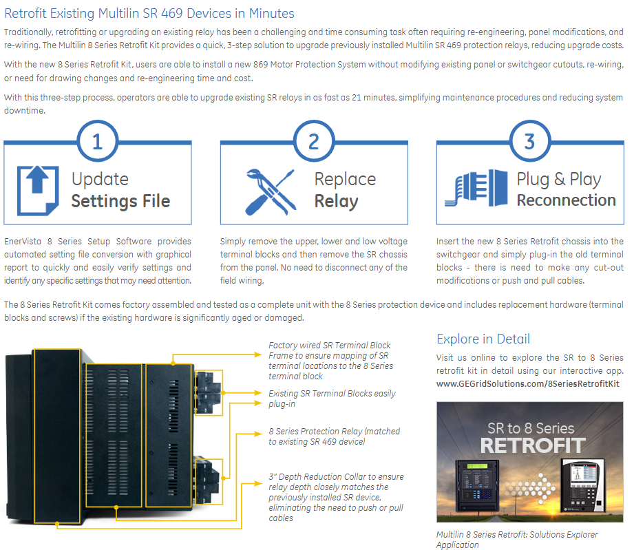
(2) Pull out structure and retrofit support
Pull out design: easy to replace quickly, reduces downtime, supports wire lead sealing to prevent unauthorized removal.
Retrofit upgrade: With the 8 series Retrofit kit, old SR 469 relays can be upgraded to 869 motor protection systems without modifying existing panel openings, rewiring, or changing drawings. The upgrade process only requires 3 steps (updating parameter files, removing old relays, plug-in reconnection) and can be completed in as fast as 21 minutes, reducing upgrade costs and system downtime.
Technical specifications and environmental adaptability
(1) Key technical parameters
Category specification details
Current measurement CT primary side 1-5000A, secondary side 1A/5A; Accuracy: ± 0.5% for current<2 times CT, ± 1% for current>2 times CT
Voltage measurement VT ratio 1.00-15.00:1, secondary side full range 273V AC; Accuracy ± 0.5% of full scale
RTD measurement supports 4 types of RTD, with a range of -50~250 ℃ and an accuracy of ± 2 ℃. Each channel has a 3-level threshold (alarm/high alarm/trip)
Communication speed serial port baud rate 300-19200 bps, Ethernet 10Mbps
Low range of power supply: DC 24-60V/AC 20-48V; High range: DC 90-300V/AC 70-265V, power 45VA (maximum)
(2) Environment and Compliance
Environmental adaptability: working temperature -40~+60 ℃, storage/transportation temperature -40~+80 ℃, humidity 0-95% (55 ℃ without condensation), protection level IP40 (front)/IP20 (back), pollution level 2.
Compliance certification: Compliant with EN60255 series, IEC 61000 series, UL508/UL1053, cULus and other standards, passed ISO9001 quality system certification, CE certification (EN60255-5/27, EN61010-1, etc.).
Ordering and configuration options
(1) Basic models and core options
Basic unit: The model starts with "469", and subsequent codes distinguish key configurations:
CT secondary side: P1 (1A), P5 (5A);
Control power supply: LO (low range: DC24-60V/AC20-48V), HI (high range: DC90-300V/AC70-265V);
Analog output: A1 (0-1mA), A20 (4-20mA);
Extended functions: D (DeviceNet), E (Enhanced Front Panel), T (Enhanced Front Panel+Ethernet), H (Anti harsh Environment Coating).
(2) Optional accessories
Including pull-out handle (with lead seal), RTD sensor, CT/VT of different specifications, Retrofit upgrade kit (including terminal block and depth reduction ring compatible with old SR relays), EnerVista software kit, etc., can be flexibly selected according to on-site needs.

- YOKOGAWA
- Reliance
- ADVANCED
- SEW
- ProSoft
- WATLOW
- Kongsberg
- FANUC
- VSD
- DCS
- PLC
- man-machine
- Covid-19
- Energy and Gender
- Energy Access
- Renewable Integration
- Energy Subsidies
- Energy and Water
- Net zero emission
- Energy Security
- Critical Minerals
- A-B
- petroleum
- Mine scale
- Sewage treatment
- cement
- architecture
- Industrial information
- New energy
- Automobile market
- electricity
- Construction site
- HIMA
- ABB
- Rockwell
- Schneider Modicon
- Siemens
- xYCOM
- Yaskawa
- Woodward
- BOSCH Rexroth
- MOOG
- General Electric
- American NI
- Rolls-Royce
- CTI
- Honeywell
- EMERSON
- MAN
- GE
- TRICONEX
- Control Wave
- ALSTOM
- AMAT
- STUDER
- KONGSBERG
- MOTOROLA
- DANAHER MOTION
- Bentley
- Galil
- EATON
- MOLEX
- Triconex
- DEIF
- B&W
- ZYGO
- Aerotech
- DANFOSS
- KOLLMORGEN
- Beijer
- Endress+Hauser
- schneider
- Foxboro
- KB
- REXROTH
- YAMAHA
- Johnson
- Westinghouse
- WAGO
- TOSHIBA
- TEKTRONIX
- BENDER
- BMCM
- SMC
- HITACHI
- HIRSCHMANN
- XP POWER
- Baldor
- Meggitt
- SHINKAWA
- Other Brands
- UniOP
- KUKA
- IBA
- Beckhoff
- ADLINK
-
ADLINK HPCI-14S12U - Industrial Control Backplane 12PCI Backplane PCI-14S Passive Backplane
-
ADLINK PCIe-GIE74C - image acquisition card 4-CH GigE Vision PoE+ Frame Grabber
-
ADLINK PCI-8164 - control card 4-Axis Advanced Motion Controller Board
-
ADLINK PCIe-U304 - 4 Port USB3 PCIe Frame Grabbers USB Screw Hole Card
-
ADLINK PCI-9112 - Multi-Function Data Acquisition Card DAQ Card
-
ADLINK PCI-7432 - 51-12013-0A50 4-CH Isolated Numérique I/O PCI Cartes Digital I/O Card
-
ADLINK PCA-6106P3-0C1 REV.C1 - backplane 6-Slot Passive Backplane Board
-
ADLINK PCI-7224 - 24-CH Opto-Isolated Digital I/O PCI Board
-
ADLINK CPCI-7433R(G) - Digital Input Board Rear I/O CompactPCI Card
-
ADLINK EBP-13E4 - 51-46703-0A30 Industrial PC Backplane Passive Backplane
-
ADLINK PCIE-HDV62 - Image acquisition card High Definition Video Frame Grabber
-
ADLINK EBP-13E4 - 51-46703-0A30 Industrial Backplane Board Passive Backplane
-
ADLINK 90111-B1 / CPCI-6770 - PCB CPU MODULE CompactPCI Single Board Computer
-
ADLINK PCI-7248 - DATA ACQUISITION PCI CARD 48-CH Parallel Digital I/O Board
-
ADLINK PCI-7230 - 51-12003-0a50 board PCI7230 32-CH Isolated Digital I/O Card
-
ADLINK PCI2A000CB - 51-20000-0B30 Multi-Function DAQ Card Baseboard
-
ADLINK PCI-8134-005 - 4-Axis Motion Controller Card
-
ADLINK PCI-7224 - 24-CH Opto-Isolated Digital I/O PCI Card
-
ADLINK PCI-7434 - 64-CH Isolated Digital Output Card
-
ADLINK PCI-8132 - motion control card 2-Axis Servo & Stepper Controller
-
ADLINK PCI-8134 - Motion Controller PCI Card 4-Axis Controller Board
-
ADLINK PCI-8164 - Motion Control Card 51-12406-0A40 4-Axis Controller
-
ADLINK 51-12001-0C20 - Circuit Board Data Acquisition Interface Module Hardware
-
ADLINK NuPR0-840 - industrial control motherboard Full-Size PICMG CPU Board
-
ADLINK PCI-7444 - 51-12023-0A10 card 128-CH Isolated Digital Output Board
-
ADLINK PCI-1612B - data acquisition card 4-Port RS-232/422/485 Serial Communication Card
-
ADLINK PCI-6208V 009 - 8/16-CH 16-Bit Analog Output Cards PCB-I-E-482=6BX3
-
ADLINK NUPRO-935A/LV - industrial control motherboard Full-Size PICMG SBC Board
-
ADLINK PCI-9114DG - Multi-Function DAQ Card Data Acquisition PCI Card
-
ADLINK ACL-7130 - Data acquisition card Isolated Digital I/O Board
-
ADLINK ABX-6300D-4E1-BP - board ABX6300D4E1BP Video Interface Expansion Card
-
ADLINK CPCI-6940 - CPCI-6940/D1539/M16-0(EA)-000E 6U CompactPCI Processor Board
-
ADLINK NuPRO-760 - industrial control motherboard Half-Size PICMG SBC CPU Board
-
ADLINK IMB-M42H (G)-0020 - industrial control motherboard LGA1155 Micro-ATX Mainboard
-
ADLINK RTV-24 / PCI-MP4S - 51-12519-1C30 4-Channel Real Time Video Capture Board
-
ADLINK PCI-8134 - 4-Axis Servo & Stepper Motion Controller Card
-
ADLINK MXC-6101D - V.PC000.002.ST.00 Box PC Configurable Embedded Computer
-
ADLINK PCI-8134A - 51-12421-0A10 Motion Control Card 4-Axis Controller Card
-
ADLINK DIN-100S / DIN-100SA1 - Technology SCSI-II TB 100-PIN Terminal Block Board
-
ADLINK DIN-812M001 / DIN812M001 - 51-14034-0A1 51140340A1 Terminal Module Breakout Interface
-
ADLINK PCI-8164 - Servo motion control 4-Axis Advanced Controller Card
-
ADLINK PCIe-GIE64 - Acquisition card GigE Vision PoE+ Frame Grabber
-
ADLINK M-302 - Industrial control motherboard ATX PC Board Mainboard
-
ADLINK PCI-8134 - Motion Controller PCI Card 4-Axis Controller Board
-
ADLINK PCI-RTV24 - Image capture card Analog Video Frame Grabber
-
ADLINK PCI-8102 - Motion control card 2-Axis Servo & Stepper Controller Board
-
ADLINK PCI-9112 REV.B1 - Card Multi-Function Data Acquisition Card
-
ADLINK HSI-DI32-M-N / HSL-TB32-M-DIN - Discrete I/O MODULE Distributed Automation Module System
-
ADLINK PCI-7296 - IO card REV.A3 96-CH Parallel Digital I/O Card
-
ADLINK DIN-814P-A4 / 814Y - terminal board Motion Control Interface Block
-
ADLINK DIN-814P-A4 - 51-14056-0A10 PCB-I-E-2736=ZA01 Screw Terminal Board Breakout
-
ADLINK M-322 - motherboard Industrial Control Computer Mainboard
-
ADLINK NUPRO-406 REV:B1 - industrial control motherboard Full-Size PICMG CPU Board
-
ADLINK AMP-204C - card DSP-Based 4-Axis Advanced Pulse-Train Controller
-
ADLINK HPCI14S REV.B1 - industrial computer baseboard 14-Slot Passive Backplane
-
ADLINK PCI-7250 - 8-CH Relay Output & 8-CH Isolated DI PCI Card
-
ADLINK EBP-13E2 - baseplate Passive Backplane Industrial Computer Chassis Board
-
ADLINK LPCI-3488A - PCI-GPIB card 51-12801-0A30 acquisition card IEEE-488 Interface Board
-
ADLINK PCI-6216V-GL - 51-12201-0C30 16-CH 16-Bit Voltage Analog Output Card
-
ADLINK ACL-8454 - 16-CH Isolated Digital I/O & 4-CH Counter Card
-
ADLINK HPCI-9S7U - backplane Passive Backplane Compatible with NuPRO-A301 852 841 842
-
ADLINK DAQ-2010-007 - Simultaneous-Sampling Multi-Function Data Acquisition Card
-
ADLINK MP-C154 - 51-64205-0A10 Motion Control Card 4-Axis Controller Board
-
ADLINK MXE-202/mSSD16B/WiFi-BT - Matrix Rugged I/O Platform Embedded Fanless Computer
-
ADLINK CM-920-R-17 - PC/104-Plus Single Board Computer Module Intel Celeron M
-
ADLINK PCI-7250 NSMP - 8-CH Relay Output & 8-CH Isolated DI Card
-
ADLINK PCI-8164 - 4-Axis Motion Controller PCI Card W/ Cable and Breakout Box
-
ADLINK EMX-100 - Ethernet-based 4-axis Motion Controllers Distributed Motion Module
-
ADLINK PCI-8134A - Press control card 4-Axis Motion Controller Board
-
ADLINK M-845EG REV:3.2 - industrial motherboard Pentium 4 Socket 478 Micro-ATX
-
ADLINK PCI-9114A Rev A2 DG - card High-Resolution Multi-Function Data Acquisition Board
-
ADLINK IEC-915GV - REV 1.1 Industrial motherboard Socket 478 CPU Board
-
ADLINK PCI-9111DG(G) - Data Acquisition Card Multi-Function DAQ Card
-
ADLINK HPCI-15S10 REV:B2 - Industrial computer base plate Passive Backplane Board
-
ADLINK NuPR0-840 / NuPR0-840DV - industrial control motherboard Full-size PICMG CPU Board
-
ADLINK RTV-24 / PCI-MP4S - 51-12519-1C30 4-Channel Real Time Video Capture Board
-
ADLINK NUPRO-780 - industrial control motherboard Pentium III Single Board Computer
-
ADLINK PCI-7296 - 0050 card 96-CH Opto-Isolated Parallel DIO Card Set
-
ADLINK NUPRO-780 - industrial control motherboard PICMG Full-Size SBC
-
ADLINK PCI-7248 - 51-12006-0A3 002 Pci 7248 48-CH Parallel Digital I/O Card
-
ADLINK cPCI-6626 - 6U CompactPCI 2.0 Blades i7-2710QE PCB-I-E-2570=9N41
-
ADLINK MXC-6322D(G) - Industrial Fanless Computer
-
ADLINK cPCI-8168-004 - CompactPci NulPC Motion Control Board 51-36402-0A3
-
ADLINK CPCI-7300[G] - COMPACTPCI Digital I/O Card Data Acquisition
-
ADLINK CPCI-6626/2710/M4G - COMPACTPCI COMPUTER BOARD
-
ADLINK cPCI-8168-009 - cPCI NulPC Motion Control Board
-
ADLINK cPCI-6626/2710/M4G - VME CPU Board Computer Board
-
ADLINK CPCI-R6200(G)-0040 - COMPACTPCI CONTROL BOARD
-
ADLINK CPCI-3840/PM18/M1G(G)-3650 - COMPACTPCI CPU Module Single Board Computer
-
ADLINK cPCI-7248 - 48-CH Opto-22 Compatible Digital I/O Module
-
ADLINK DLAP-211-JNX - NVIDIA Jetson Xavier NX Edge AI Inference Platform
-
ADLINK cPCI-3544 - Series 4-Port RS-422/485 Isolated Serial Communications Card
-
ADLINK CM1-86DX3 - PC/104 SBC Stanley Vortex86DX3 CPU 2GB Ram
-
ADLINK DLAP-211-JNX - NVIDIA Jetson Xavier NX Edge AI Inference Platform
-
ADLINK cPCI-3544 - Series 4-Port RS-422/485 Isolated Serial Communications Card
-
ADLINK CM1-86DX3 - PC/104 SBC Stanley Vortex86DX3 CPU 2GB Ram
-
ADLINK PCI-7433 - switch value acquisition card Isolated Digital Input Card
-
ADLINK PCI-9112 - 51-12252-0D20 Multi-Function Data Acquisition Card
-
ADLINK NUPRO-A301 REV:1.4 - industrial control motherboard PICMG Full-Size SBC
-
ADLINK 51-18502-0A10 - Frame Grabber Image Acquisition Interface Card
-
ADLINK PCI-7296 - 51-12009-0A50 PCB-I-E-925=6DX1 96-CH Parallel Digital I/O Board
-
ADLINK PCI-8132 GP A2 - Motion Control Card 2-Axis Servo & Stepper Controller
-
ADLINK PCI-7442 - switch quantity card data acquisition card 64-CH Isolated Card
-
ADLINK HPX-13S4 - baseboard PICMG 1.3 Passive Backplane Chassis Baseplate
-
ADLINK NuPRO-590 / NTC-567-ZM-F36 - Single Board Computer PCB-I-E-1853=9L21 Half-Size SBC
-
ADLINK PCIe-8332 - 16-axis plate Motion Control Hardware Card
-
ADLINK NuPRO-775 REV.B1 - motherboard Pentium 4 Full-Size PICMG SBC
-
ADLINK PXI-3920 - Embedded Controller 3U PXI cPCI System Intelligence Board
-
ADLINK PCI-8134 - driver card motion control card 4-Axis Controller Board
-
ADLINK HSL-DI32-M-N-011 / HSL-TB32-M-DIN - Digital Input & Base Module PLC Distributed I/O System
-
ADLINK PCI-6216V-206 / PCI-208V 009 - 16 CH 16bit analog output card
-
ADLINK NuPro-E330 - 51-41805-0A20 PCB Single Board Computer Host Board
-
ADLINK PCI-1622C - Card 8-Port RS-232/422/485 PCI Serial Communication Board
-
ADLINK PCIe-7432 - 51-18402-0A10 Carte PCIe Avec Plage D'Entrée Élevée Isolated DIO Card
-
ADLINK PCI-7250 - PCI Acquisition Card 8-CH Relay Output Isolated DI Card
-
ADLINK PCI-7230 - 32-CH Isolated Digital I/O Card
-
ADLINK PCI-8164 - PCB 4-Axis Motion Controller Card
-
ADLINK PCI-7854 - Collection card High-Speed Link Distributed Motion Controller
-
ADLINK NuPRO-935A/LV - industrial control computer motherboard Full-Size PICMG SBC
-
ADLINK IMB-M40H - motherboard IH61-AA4 1155 LGA1155 Micro-ATX Mainboard
-
ADLINK PCI-7248 - Linhua 51-12006-0A40 48-CH Parallel Digital I/O Card
-
ADLINK HPCI-14S12U - Linhua industrial computer baseboard Passive Backplane
-
ADLINK PCI-8132 Rev.A2 - 2-Axis Servo & Stepper Motion Controller Card
-
ADLINK ACL-8111 - ISA card Multi-Function DAQ Card
-
ADLINK ACL-8111 - ISA card Multi-Function Data Acquisition Board
-
ADLINK PCI-7200 REV.A3 - Digital I/O card 12MB/s High-Speed Parallel Digital I/O
-
ADLINK PCI-7296 REV.A3 - 96-CH High-Density Opto-Isolated DIO Card
-
ADLINK PCI-7434 - 64-CH Isolated Digital Output Card

K-JIANG

Add: Jimei North Road, Jimei District, Xiamen, Fujian, China
Tell:+86-15305925923