
K-WANG


Tektronix TBS1000 series digital storage oscilloscope
Tektronix TBS1000 series digital storage oscilloscope
Product model and core parameters
The TBS1000 series includes 5 models, and the key parameter differences are shown in the following table:
Model Channel Number Bandwidth Maximum Sampling Rate Display Type
TBS1022 2 25 MHz 500 MS/s color
TBS1042 2 40 MHz 500 MS/s color
TBS1062 2 60 MHz 1 GS/s color
TBS1102 2 100 MHz 1 GS/s color
TBS1152 2 150 MHz 1 GS/s color
Basic Operation Guide
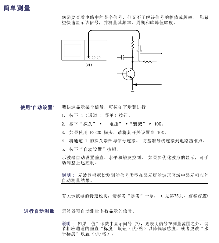
1. Installation and functional inspection
Installation requirements: The power cord must comply with the specific specifications of the equipment, with a power supply voltage of 90-264VAC (45-66Hz) or 90-132VAC (400Hz); The equipment is cooled by convection, leaving 2 inches of space at both ends and top.
Functional inspection steps:
After booting up, press the Default Setup button to reset to the factory state;
Connect the TPP0101/TPP0201 probe to channel 1, and connect the probe end/reference wire to the "probe compensation" terminal;
Press AutoSet, and after a few seconds, a square wave of approximately 5V peak to peak and 1kHz will be displayed;
Repeat the operation of channel 2 (check channels 3-4 for 4-channel models) and confirm that all channels are functioning properly.
2. Probe calibration and setting
Probe Inspection Wizard: Press the PROBE CHECK button, and the oscilloscope will automatically verify the probe compensation and attenuation coefficient matching (supporting 1X/10X/20X/50X/100X). If it is qualified, it will display "qualified", otherwise it will prompt correction.
Manual probe compensation:
Channel menu → "Probe" → "Voltage" → "Attenuation" set to 10X, P2220 probe switch adjusted to 10X;
Connect the probe to the "probe compensation" terminal and display a square wave according to AutoSet;
Adjust the probe compensation screw until the waveform is "compensated correctly" (no overcompensation/overcompensation).
Current probe settings: Channel menu → "Probe" → "Current" → "Ratio", default 10A/V, need to match the ratio of the current probe.
3. Core control operations
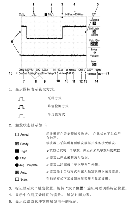
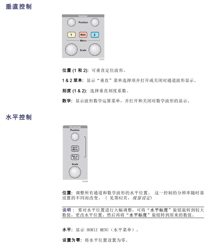
(1) Vertical control
Coupling: DC (AC/DC), AC (DC blocking, attenuation<10Hz signal), grounding (disconnected input);
Bandwidth limit: 20MHz bandwidth limit can be enabled to reduce high-frequency noise;
Scale and Position: The "Vertical Scale" knob adjusts the voltage/grid (1-2-5 sequence, fine adjustment can set small steps), and the "Vertical Position" knob moves the waveform up and down.
(2) Horizontal control
Time base range: 5ns-50s/grid (1-2.5-5 sequence), corresponding relationship of sampling rate is as follows (partially):
Time base setting sampling rate maximum measurable frequency (Nyquist frequency)
5.0ns-250.0ns 1 GS/s 150.0 MHz
500.0ns 500.0 MS/s 150.0 MHz
1.0μs 250.0 MS/s 125.0 MHz
Window function: Open the "Window Settings" through the "Horizontal Menu", define the waveform segment and zoom in to view, supporting switching between the main time base and window view.
(3) Trigger control
Trigger type:
Edge trigger: rising/falling edge, optional source of CH1/CH2/ext/ext/5/mains power, coupling supports DC/AC/noise suppression, etc;
Video trigger: Supports NTSC/PAL/SECAM standards, synchronizes optional scan lines/line numbers/odd fields/even fields/all fields;
Pulse width triggering: The triggering conditions are=(± 5% tolerance), ≠,<,>, and the pulse width range is 33ns-10s.
Key buttons: "Set to 50%" (trigger level set to signal midpoint), "Force trigger" (complete acquisition regardless of trigger conditions), "Trig View" (hold down to view trigger signal).
Functional applications and examples
1. Signal measurement
(1) Automatic measurement
Supports 16 measurement types, with a maximum of 5 displayed at once. Some types are defined as follows:
Measurement type definition applicable scenarios
Frequency measurement, first cycle calculation, frequency cycle signal frequency detection
Measurement of the amplitude range of the absolute difference signal between the maximum and minimum peak values of the peak to peak waveform
Evaluation of edge velocity of time pulse signal between 10% -90% rising edge of rising time waveform
Synchronization analysis of phase difference signal between rising edges of two channel phase signals
Determination of pulse signal symmetry based on the proportion of duty cycle, positive pulse time, and period
Operation steps: Press the Measure button → Select the source → Select the measurement type → View the reading (including real-time updates).
(2) Cursor measurement
Type: Time cursor (vertical line, measuring time/frequency/amplitude), amplitude cursor (horizontal line, measuring voltage/current);
Example: Measure pulse width → Press cursor → Select "time" from "type" → Move cursor 1/2 to the rising/falling edge of the pulse → Read and display Δ t (pulse width).
2. Advanced analysis function
(1) FFT analysis
Function: Convert time-domain (YT) signals into frequency-domain spectra, supporting 1024 data points (0Hz Nyquist frequency);
Window selection:
Window type characteristics applicable scenarios
Hanning has good frequency accuracy and average amplitude accuracy for periodic waveform frequency analysis
Flattop has good amplitude accuracy, and its frequency accuracy is generally good for measuring the amplitude of periodic waveforms
Rectangular without attenuation, equivalent to windowless pulse/instantaneous waveform
Operation: Math → "Operation" Select FFT → Select source → Adjust scaling (horizontal X1-X10, vertical X0.5-X10).
(2) Data recording and limit testing
Data recording:
Utility → "Data Recording" → Enable → Select Source (Channel/Mathematical Waveform);
Set the recording duration (0.5-24 hours, increments of 30 minutes/60 minutes, or unlimited);
Select storage folder → start collection, and automatically save to USB after completion.
Extreme testing:
Utility → "Extreme Testing" → Define the source and template (internal/external waveform+horizontal/vertical tolerance);
Set violation response (waveform/image storage) and stop conditions (number of waveforms/violation times/time/manual);
Start the test and display the pass/fail statistics after completion.
3. Typical application examples
(1) Capture single pulse signals (such as relay arcing)
Set the expected range for vertical/horizontal scaling, Acquire → "Peak Detection";
Trigger menu → select "Slope" to rise, set the trigger level to the midpoint of the relay switch voltage;
Press Single to trigger the collection when the relay is turned on. After optimizing the settings, collect and observe the rebound of the contacts again.
(2) Video signal trigger (NTSC standard)
Probe connected to video output, AutoSet → "Auto Settings" menu select "Field" → "All Fields";
Trigger menu → "Video" → "Standard" select NTSC, "Sync" select "Odd Field" (only watch odd fields);
Rotate the horizontal scale to display the complete field/line, and the vertical scale ensures full signal display.
Data management and peripheral connectivity
1. USB flash drive operation
Support capacity: ≤ 64GB, file storage capacity (every 1MB): 5 full storage, 16 images, 250 settings, 18 waveforms;
Save function:
Full Storage: Press Save/Recall → "Full Storage" → "Print Button" to set "Full Storage", press the Print Button to save the image+waveform+settings to the ALLnnnn folder;
Save separately: "Save Image" (BMP/JPG format, etc.), "Save Settings" (. SET), "Save Waveform" (. CSV, 2500 data points);
Transfer function: Transfer settings (. SET) or waveforms (to RefA/RefB reference memory) from USB.
2. Peripheral connection
Printer: Connect a PictBridge compatible printer, go to Utility ->"Options" ->"Printer Settings" (ink saving/layout format), press the print button to send the image, and support terminating printing.
PC connection:
Install OpenChoice software (official website download);
Connect the oscilloscope USB device port to the PC using a USB cable;
Follow the prompts to complete the driver installation and transfer data/control the oscilloscope through software.
GPIB connection: Use the TEK-USB-488 adapter, go to "Utility" → "Options" → "GPIB Settings" to set the address (default 1), connect to the GPIB system, and control it through software.
Reference and Appendix
1. Technical specifications (core part)
Vertical specifications: 8-bit resolution (>6.5 bits at 2mV/grid), DC gain accuracy ± 3% (5V-10mV/grid), ± 4% (5mV/2mV/grid);
Horizontal specifications: Long term time accuracy ± 50ppm (≥ 1ms interval), incremental time accuracy ± (1 sampling interval+100ppm × | reading |+0.6ns) (single sampling);
Environmental requirements: working temperature 0-50 ℃, humidity 5% -85% (no condensation), altitude ≤ 3000m.
2. Accessories and Maintenance
Standard attachments: TPP0101 (100MHz)/TPP0201 (200MHz) 10X passive probe, installation and safety manual, customer documentation browser CD;
Optional accessories: RM2000B rack kit, TEK-USB-488 adapter, soft box (AC2100), handling box (HCTEK4321);
Cleaning and maintenance: Use a lint free cloth to remove dust, clean the outer surface with a soft cloth and 75% isopropanol, and avoid abrasive reagents/direct sunlight/humid environments.
- YOKOGAWA
- Reliance
- ADVANCED
- SEW
- ProSoft
- WATLOW
- Kongsberg
- FANUC
- VSD
- DCS
- PLC
- man-machine
- Covid-19
- Energy and Gender
- Energy Access
- Renewable Integration
- Energy Subsidies
- Energy and Water
- Net zero emission
- Energy Security
- Critical Minerals
- A-B
- petroleum
- Mine scale
- Sewage treatment
- cement
- architecture
- Industrial information
- New energy
- Automobile market
- electricity
- Construction site
- HIMA
- ABB
- Rockwell
- Schneider Modicon
- Siemens
- xYCOM
- Yaskawa
- Woodward
- BOSCH Rexroth
- MOOG
- General Electric
- American NI
- Rolls-Royce
- CTI
- Honeywell
- EMERSON
- MAN
- GE
- TRICONEX
- Control Wave
- ALSTOM
- AMAT
- STUDER
- KONGSBERG
- MOTOROLA
- DANAHER MOTION
- Bentley
- Galil
- EATON
- MOLEX
- Triconex
- DEIF
- B&W
- ZYGO
- Aerotech
- DANFOSS
- KOLLMORGEN
- Beijer
- Endress+Hauser
- schneider
- Foxboro
- KB
- REXROTH
- YAMAHA
- Johnson
- Westinghouse
- WAGO
- TOSHIBA
- TEKTRONIX
- BENDER
- BMCM
- SMC
- HITACHI
- HIRSCHMANN
- XP POWER
- Baldor
- Meggitt
- SHINKAWA
- Other Brands
- UniOP
- KUKA
- IBA
- Beckhoff
-
ADLINK CPCI-6860A - 51-31310-OB10 industrial motherboard CompactPCI SBC
-
ADLINK AmITX-SL-G-H110 - 51-7A104-0A30 Mini-ITX Industrial Motherboard
-
ADLINK PXI-2005-003 - CPCI Industrial PC Data Acquisition Card Multi-Function DAQ
-
ADLINK DININ-814M - 51-14032-0A3D SCSI-100P cable connection Interface Terminal Board
-
ADLINK CPCI-3920NA/C2D15/M1G - 3U CompactPCI Intel Core 2 Duo Single Board Computer
-
ADLINK PCIE-8560 - 51-18014-0A20 Communication Card High Speed DAQ
-
ADLINK PCI-C154+ - Motion Control Card 4-axis Motion Controller Board
-
ADLINK PCI-RTV24 - image capture card Analog Video Frame Grabber
-
ADLINK NuPRO-842LV/P - 51-41360-0B30 Industrial Motherboard CPU Board
-
ADLINK cBP-3208/3208R - CPCI Board 3U 8-Slot CompactPCI Backplane
-
ADLINK PCI-8164 - 4-Axis Motion Controller PCI Card 51-12406-0A40
-
ADLINK PCIe-GIE64+ - 4-CH GigE Vision PoE+ Frame Grabber Video Capture Card
-
ADLINK CPCI-6860 / 6860A - CompactPCI Dual Xeon Single Board Computer
-
ADLINK IEC-915GV - REV 1.1 Industrial motherboard CPU Board
-
ADLINK ND-6520 - Technology RS-232 to RS-422RS-485 Converter NuDAM Module
-
ADLINK RTV-24 / PCI-MP4S - 51-12519-1C30 4-Channel Real Time Video Capture Board
-
ADLINK cPCI-6910 / cPCI-6910AM/M1G - cPCI-6910AM/DXL16/M1G/S80G(G)-3120 BOARD CompactPCI SBC
-
ADLINK NUPRO-A40H - Linghua 51-41807-1A30 Industrial Control Computer Motherboard
-
ADLINK USB-3488A - USB to GPIB INTERFACE USB-3488A(G) Controller Module
-
ADLINK PCI-8134A - motion control card 4-Axis Controller Card
-
ADLINK PCI-7432 - Board 32-Channel input / 32-output Isolated Digital I/O PCI Card
-
ADLINK PCI-8134A - 51-12421-0A10 motion controller card tested
-
ADLINK LPCIe-7230 - 32 CH Isolated Input/output Card 2 Interrupts Low Profile PCIe
-
ADLINK NuPRO-E340 - industrial computer motherboard 51-47807-0A30 PICMG 1.3 SHB
-
ADLINK PCI-7434 - High-speed Digital Acquisition Card 64-CH Isolated DO Card
-
ADLINK NuPRO-E330 - 51-41805-0A20 Indsutrial Board SHB Single Board Computer
-
ADLINK PCI-7248 - OPTO-22 48 CHANNEL DIO DIGITAL TTL/DTL I/O 51-12006-0A40 GP
-
ADLINK PCI-8134 - Motion control card 4-Axis Controller Card
-
ADLINK AMP-208C - Movimiento Control Tarjeta 51-12420-1A20 W/Expansión & Breakout
-
ADLINK PCI-8164 - 51-12406-0A40 PCB Board 4-Axis Motion Controller Card
-
ADLINK DIN-68Y-SGII / DIN-68M-J3A - Terminal Board Connector Interface Block
-
ADLINK PCIe-7432 - Technology 51-18402-0A10 PCIe Card With High Input Range
-
ADLINK PCI-8144 / PCI-8144N - Motion control card 4-Axis Stepper Controller Card
-
ADLINK HSL-HUB3/REPEATER - HIGH SPEED LINK EXTENSION MODULES Distributed Hub Module
-
ADLINK ND-6017 - Data Logging + Acquisition 8CH A/D input Mod NuDAM Module
-
ADLINK LPCIe-7250 - data acquisition card Low Profile 8-CH Relay Output Card
-
ADLINK PCI-7432 - I/O card 64-CH Isolated Digital Input Output PCI Card
-
ADLINK IMB-M43H - industrial control computer motherboard Q87 Chip Micro-ATX
-
ADLINK MP-C154 - Motion control Card 4-Axis Motion Controller Board
-
ADLINK PCI-RTV24 - image capture card Video Frame Grabber Card
-
ADLINK PCI-7250 - 8-CH Relay Output & 8-CH Isolated DI Card
-
ADLINK PCI-6308V - 8-CH 12-Bit Isolated Analog Output PCI Card PCB-I-E-1148=6EX2
-
ADLINK PCI-7248 - capture card 48-CH Opto-22 Compatible DIO Card
-
ADLINK HSL-AI16A02-M-VV - Analog Input Output Distributed Module
-
ADLINK NuPRO-A301 - Rev:1.4 NUPRO-A301 PICMG Full-Size Single Board Computer
-
ADLINK PCI-6208V-GL - 8-CH Voltage Analog Output PCI Card
-
ADLINK PCI-8134A - 51-12421-0A10 4-Axis Motion Controller Card
-
ADLINK MNET-S23 - TECHNOLOGY MNET S23 - SERVO DRIVER CONTROL MODULE
-
ADLINK M-342 - ATX I3 I5 I7 Q67 Industrial Motherboard
-
ADLINK NUPRO-780 - Industrial Motherboard CPU Board PICMG SBC
-
ADLINK MP-C154 / MP-C152 - 4-Axis Motion Control Card Pulse-Train Controller
-
ADLINK NuPRO-935A/LV10B0 - Motherboard 51-41802-0A10 GP w/RAM Industrial Control Board
-
ADLINK MP-C154 - Motion control card 4-Axis Motion Controller Mainboard
-
ADLINK PCI-7250 - PCI Acquisition Card 8-CH Relay Output Isolated DI Card
-
ADLINK ACL-7124 - Technology Inc.24 DIO Card Digital Input Output Card
-
ADLINK PCI-8554 A2 - Timer/Counter Data Acquisition Card
-
ADLINK DIN-825-GP4 - Terminal Block Interface Board Breakout Module
-
ADLINK NuPR0-761 - REV:1.1 Industrial motherboard Full-Size PICMG SBC
-
ADLINK MXE-1401/M8G (G) - Matrix Fanless Embedded Computer Industrial PC
-
ADLINK HSL-DI16DO16-UD-NN - Digital 16 Channel I/O Mod Distributed I/O Module
-
ADLINK ND6520 - NUDAM INTELLIGENT DA&C MODULE RS232-RS-422/RS485 CONVERTOR
-
ADLINK NUPRO-761 - REV:1.1 Industrial Motherboard CPU Board
-
ADLINK AMP-208C - Motion Control Card 51-12420-1A20 DSP-based 8-axis
-
ADLINK NuPRO-A301REV 1.4 - with packaging industrial computer motherboard PICMG SBC
-
ADLINK PCM-9112+ - 51-12300-0A2 industrial motherboard Multi-Function DAQ PC/104 Module
-
ADLINK PCM-7250+ - 8-CH Relay Outputs & 8-CH Isolated DI Module PC/104
-
ADLINK PCI-RTV24 - Image capture card Analog Video Frame Grabber
-
ADLINK PCI-8134 - Motion Controller PCI Card 4-Axis Controller Board
-
ADLINK PCI-7432 - Isolated Digital I/O PCI Card
-
ADLINK PCI-8554 A2 - acquisition card Timer/Counter Card
-
ADLINK PCI-8132 - Rev.A2 2-Axis Servo & Stepper Motion Controller Card
-
ADLINK PCI-8132 - Data Acquisition card 2-Axis Motion Controller Card
-
ADLINK EBP-13E4 - 51-46703-0A30 Industrial Backplane Board Passive Backplane
-
ADLINK PCI-800L - Electronic Card Interface Controller Card
-
ADLINK PCIe-GIE72 - 51-18531-0A10 PCB Board GigE Vision Frame Grabber
-
ADLINK DAQ-2010(G)-OOBO - Simultaneous-Sampling Multi-Function DAQ Card
-
ADLINK PCI-9112 - REV.B1 Multifunction DAQ Card Data Acquisition Card
-
ADLINK PCI-7230 - 51-12003-DA60 32-CH Isolated Digital I/O Card
-
ADLINK PCI-7432 - Data Acquisition Card Isolated Digital I/O PCI Card
-
ADLINK ETX-AT-N270-18/LXE - 51-71111-0A20 ETX CPU Module Motherboard
-
ADLINK HSL-DI32-UD-N - DIGITAL INPUT 32 POINTS MODULE Distributed I/O
-
ADLINK AMP-204C - Motion Control card DSP-Based 4-Axis Advanced Controller
-
ADLINK MNET-4XMOG-0050 - Four-axis Motion Controller Distributed Motion Module
-
ADLINK AMP-204C - Motion control card DSP-Based 4-Axis Pulse-Train Controller
-
ADLINK PCI-7442 - Switch card 64-Channel Datalogging & Acquisition Card
-
ADLINK M-302 - Industrial control motherboard ATX PC Board
-
ADLINK NUPRO-852 / NUPRO-852LV - Industrial motherboard Single Board Computer
-
ADLINK PCI-8134 - REV.B1. 4-Axis Motion Controller Card
-
ADLINK PCI-GIE62 + - 51-18502-0A20 2-CH GigE Vision Frame Grabber PoE Card
-
ADLINK PCI-MPG24 - 51-12523-0B20 MPEG4 Card Video Compression Hardware
-
ADLINK HSL-TB32-M-DIN - 32-CH I/O TERMINAL W/ HSL-AI16AO2-M-VV MODULE
-
ADLINK PCI-M114-GL - PCB Ver 2.1 Motion Controller Axis Card
-
ADLINK IMB-M40H - SYM76996H61 motherboard Industrial Computer Mainboard
-
ADLINK NUPRO-A40H - 51-41807-1A20 industrial control motherboard H61 Chip
-
ADLINK PCI-M114-GL - Axis Card Data Acquisition Card PCB VER2.2 Motion Controller
-
ADLINK PCI-8134 - Motion Controller PCI Card 4-Axis Controller Board
-
ADLINK PCI-8102 - Motion control card 2-Axis Servo & Stepper Controller
-
ADLINK NuPRO-841REV:3.0 - motherboard Industrial Control PC Board
-
ADLINK HSL-TB32-U-DIN REV A1 - Breakout Terminal Board Field I/O Module
-
ADLINK AMP-204C - Motion Control card DSP-Based 4-Axis Pulse-Train Controller
-
ADLINK NUPRO-A40H - 51-41807-1A20 industrial control motherboard H61 PC Board
-
ADLINK PCI-6308A / PCI-6308V - 51-12202-0A50 Isolated Analog Output Card
-
ADLINK AMP-204C - DSP-Based 4-Axis Advanced Pulse-Train Motion Controller
-
ADLINK PCI-7434 - Technology 64-Channel Isolated Digital I/O PCI Cards
-
ADLINK CPCI-6840 / CPCI-6840V / PM16/M1G-12G0 - CompactPCI Single Board Computer CPU Module
-
ADLINK PCIE-GIE74 - Motherboard Video Capture Card 51-18531-0A10 Frame Grabber
-
ADLINK NuPRO-E330 - industrial computer equipment motherboard Control Mainboard
-
ADLINK AMP-208C / 51-12420-1A20 - Motion Control Card W/ Expansion & Breakout Board
-
ADLINK HPCI-14S12U - industrial computer baseboard Passive Backplane 14 Slots
-
ADLINK PCI-8164 - 4-Axis Motion Controller PCI Card W/ 1x Cable, 1x Breakout Box
-
ADLINK PCIe-RTV24 - 51-18016-0A20 Image Acquisition Video Capture Card
-
ADLINK M-342 - 5 PCI ATX Motherboard Industrial PC Mainboard
-
ADLINK PCI-FIW64 - 4/2 Channel IEEE1394B Image Capture Card FireWire Frame Grabber
-
ADLINK PCI-7432 - digital IO card 64-CH Isolated Digital Input Output Card
-
ADLINK 51-12001-0C20 - Circuit Board PCI-7200 Data Acquisition Controller Card
-
ADLINK PXI-3920 - PXI 3U cPCI Industrial Controller Embedded System CPU Board
-
ADLINK NuPRO-841REV:2.0 - motherboard Industrial Control PC Board
-
ADLINK NuPro-E330 - 51-41805-0A20 PCB Industrial Control Computer Motherboard
-
ADLINK PCI-RTV24 - Image capture card Analog Video Frame Grabber
-
ADLINK PCI-7442 - Switch card 64-Channel Datalogging & Acquisition Card
-
ADLINK HPX-13S4 - device baseboard Passive Backplane Riser Card
-
ADLINK PCI-9112 REV A.1 - Multi Function DA&C Board Data Acquisition Card
-
ADLINK PCI-7248 - 51-12006-0A40 Card Control 48-CH Digital I/O Module
-
ADLINK CPCI-6860 / 6860A - motherboard CompactPCI Dual Xeon Single Board Computer
-
ADLINK DPAC-3020-11(G) - Embedded PC Automation Controller Machine Control Board
-
ADLINK NuPRO-841 REV:1.0 - industrial control motherboard CPU Board
-
ADLINK MNET-4XMOG-0050 - Four-axis Motion Controller MNET Motion Control Card
-
ADLINK ETX-AT-N270-18/LXE - 51-71111-0A20 ETX CPU Module Motherboard

K-JIANG

Add: Jimei North Road, Jimei District, Xiamen, Fujian, China
Tell:+86-15305925923