
K-WANG


Tektronix 4000 series oscilloscope
Tektronix 4000 series oscilloscope
Introduction to Tektronix 4000 Series (Basic Function Demonstration)
1. Demo I: Collecting Signals
Step: ① Connect the oscilloscope (front/rear panel USB port) to the device port on the demonstration board using a USB cable; ② Confirm that the "USB POWER" LED on the demonstration board is on; ③ P6139A probe (channel 1) is connected to the demonstration board "GND" and "CNT CLK" (synchronous counter clock); ④ Press' Default Setup 'to reset; ⑤ Press' Auto Settings' to display multiple cycle clock signals.
2. Demo II: Using Vertical Controls
Operation: ① Rotate the vertical "scale" knob of channel 1 (observe the change in volts/grid, set to 1 V/grid); ② Rotate the vertical "position" knob (waveform centered); ③ Press the channel 2 button (switch channel 2).
3. Demo III: Using Horizontal Controls
Operation: ① Rotate the horizontal "scale" knob (observe time/grid changes, set to 20 ns/grid); ② Rotate the horizontal "position" knob (adjust the trigger position icon to the center of the screen); ③ Identify the display identifier (yellow bar=all collected, gray square brackets=current display section).
4. Demo IV: Using the Run/Stop Control
Operation: ① Press "Run/Stop" (stop collecting and display the last waveform); ② Press' Single '(stop after collecting a single waveform); ③ Press' Run/Stop 'again (restart collection).
5. Demo V: Using Trigger Controls
Operation: ① Rotate the trigger "position" knob (move it outside the waveform, and the waveform will randomly scroll); ② Press' Force trigger '(display single waveform acquisition); ③ Press' Set to 50% '(trigger level set to signal midpoint, stable trigger).
6. Demo VI: Using the cursor
Step: ① Press the "cursor" button (display vertical cursor, reading includes time/amplitude/increment); ② Use the multifunctional A/B knob to move the cursor (switch fine adjustment mode with the "Fine" button); ③ Measurement cycle (with the cursor placed at the midpoint of two falling edges, with a difference of approximately 100 ns); ④ Press the 'cursor' twice to close.
7. Demo VII: Measurement
Step: ① Press the "Measure" button; ② Click on the 'Select Measurement' button below; ③ Select "cycle" and "frequency"; ④ View readings (including value, average, minimum, maximum, standard deviation, such as frequency of approximately 10.0M); ⑤ Delete measurement ("Delete Measurement" → "Delete All Measurements"); ⑥ Press' Menu Off 'to close the menu.
8. Demo VIII: Saving Screen Images
Step: ① Insert USB/CompactFlash; ② Press' Save/Recall Menu '; ③ Select 'Save Screen Image'; ④ Multi function knob A selects the driver; ⑤ Press' Select '(expand/shrink directory); ⑥ Select file format (such as. png); ⑦ Press' OK to save screen image '; ⑧ Quick save (press the "Save" button, default image saved, can change saved content).
Tektronix 4000 Advanced Feature Demonstration
1. Overall packaging and performance
(1) Overall packaging advantages
10.4-inch XGA large display (high brightness, visually friendly);
Each channel has an independent vertical control knob (no need to select a channel first, efficient and intuitive);
Front and rear USB and CompactFlash ports (convenient for transferring data);
Thickness of 5.4 inches (saving workspace);
Weight 11 pounds (4.99 kilograms), with handle (portable);
Supports 11 languages (including Simplified/Traditional Chinese).
(2) Performance Parameters (Table)
Product Model Bandwidth Channels (DPO/MSO) Maximum Analog Sampling Rate (All Channels) Main Record Length (All Channels) MSO MagniVu Record Length (All Digital Channels)
DPO4104 & MSO4104 1 GHz 4 / 4+16 5 GS/s 10 M 10 K
DPO4054 & MSO4054 500 MHz 4 / 4+16 2.5 GS/s 10 M 10 K
DPO4034 & MSO4034 350 MHz 4 / 4+16 2.5 GS/s 10 M 10 K
DPO4032 & MSO4032 350 MHz 2 / 2+16 2.5 GS/s 10 M 10 K
Additional performance: All channels ≥ 5X oversampling (sin (x)/x interpolation, single full bandwidth); All channels have a record length of 10 meters; Support waveform labels.
2. Wave Inspector Demonstration
(1) Demo IX: Setting I2C Signal
Step: ① P6139A probe (channel 1 → SCLK, channel 2 → I2C SDA, all connected to GND); ② Confirm that the I2C LED is on (press "Serial SELECT" until it lights up); ③ Press' Default Setup '; ④ Trigger the "position" knob to set the trigger level to ≈ 2 V; ⑤ Open channel 2; ⑥ Channel 1/2 vertical "scale" is set at 2.0 V/grid, with positions at the top/middle of the scale respectively; ⑦ Press "Collect" → "Record Length" → "1M Points"; ⑧ Set the horizontal "scale" to 20.0 ms/grid; ⑨ Press' Single 'to display I2C clock (ch1 yellow) and data (ch2 blue).
(2) Demo X: Zoom and Pan Functions
Core control: Wave Inspector "pan/zoom" knob (outer ring=pan, inner ring=zoom);
Operation: ① Turn the zoom knob clockwise (enable zoom, display full capture/current display/zoom view); ② Amplify to a single clock pulse; ③ Translation knob (counterclockwise=left shift zoom box, clockwise=right shift, 10M recording length can be quickly moved); ④ Play/Pause "(automatically scrolling waveforms, adjusting speed/direction by moving the knob); ⑤ Set/Clear "(mark, solid white triangle=bookmark); ⑥ Arrow buttons (navigation markers).
(3) Demo XI: Search Function
Step: ① Press "Search" ->"Search" on the lower bezel ->"Turn on" on the side bezel; ② Clear all tags; ③ Select "Pulse" for "Search Type", select 2 for "Source", and set "Positive" for "Polarity"; ④ The threshold is set to ≈ 2.00 V (midpoint of channel 2 waveform); ⑤ Select "Pulse width<8.00 ns" for "Set marking time" and adjust it to 5 μ s (display hollow triangle mark, event number displayed in the bottom left corner); ⑥ Arrow button navigation markers; ⑦ Zoom in and observe (e.g. 5kX zoom); ⑧ Close search (Search → Close).
3. Serial triggering and analysis
(1) Demo XII: Serial Triggering and Analysis (Using I2C as an Example)
Step: ① Adjust the scaling factor by 50X and pan to the target view; ② Press B1 → "Bus" and select "I2C"; ③ Define Input "(SCLK=Channel 1, SDA=Channel 2); ④ Set the midpoint of the waveform as the "threshold"; ⑤“Menu Off”; ⑥ Zoom observation (green bar=packet start, yellow box=address, cyan box=data, red box=lost confirmation, red bar=stop); ⑦ Switch between "binary/hexadecimal" for "bus display"; ⑧ Event Table "(displays packet timestamps when enabled, similar to a logic analyzer); ⑨ Trigger settings: "Trigger menu" → "Type" select "Bus" → "Signal source bus" select B1 → "Address" set to 50 (hexadecimal), "Direction" set to "Write" → "Single" acquisition → Zoom to view trigger content.
(2) Demo XIII: Searching for Serial Signals (Taking I2C as an Example)
Step: ① "Trigger menu" ->"Type", select "Edge" ->"Single time" collection; ② Select "Bus" for "Search" → "Search Type", choose B1 for "Source Bus"; ③ Select "Start" for "Search" → Arrow button navigation mark; ④ Select "Address" for "Search", set to 76 (hexadecimal) → decrease results; ⑤ Save all tags "(hollow to solid, old tags can be retained).
(3) Demo XIV: Monitoring and Decoding RS-232
Prerequisite: Install DPO4COMP application module;
Step: ① P6139A (Channel 1 → RS-232 TX, connected to GND); ② Press' Serial SELECT 'until the RS-232 LED lights up; ③ Default Setup "→" Auto Settings "→" Collection "→" Record Length "=1M points; ④ Set the horizontal "scale" to 20 ms/grid; ⑤ Press B1 → "Bus" and select "RS-232"; ⑥ Define Input "with channel 1 as" Send Input "and" Configure "with a bit rate of 9600; ⑦ Select "ASCII" ->"Single" ->Scale 10X (read characters) for "Bus Display"; ⑧ Play "scrolling messages; ⑨ Event Table "(displaying a list of characters).
(4) Demo XV: Serial Data Pattern Triggering (Using RS-232 as an Example)
Step: ① "Trigger Menu" → "Type" Select "Bus" → "Signal Source Bus" Select RS-232 B1; ② Trigger Open "and select" Send Data "; ③ Set "Data" to 51 (hexadecimal, corresponding to ASCII "Q"); ④ Menu Off "→" Single "; ⑤ Display the word 'Restart' (triggered successfully).
MSO4000 Function Demonstration
1. Core Features
(1) Usability
Wave Inspector supports digital channels (zoom/pan/search/mark);
P6516 digital probe (dual eight channel longitudinal slot, blue coaxial cable identification channel, can be self-made grounding wire);
Color coded display (green=high level, blue=low level, white edge=multiple transitions, gray blur=edge uncertainty).
(2) Performance
16 digital channels (added on the basis of DPO);
MagniVu function (10000 point sampling, 60.6ps timing resolution, 16.5 GS/s sampling rate, switchable main recording/MagniVu recording);
Threshold setting for each channel (supporting multiple logical series);
Supports 4 buses (serial/parallel);
Establish/maintain bus triggering (including 16 digital+4 analog channels, auxiliary input can be expanded to 20 channels);
Parallel bus triggering (user-defined logical mode);
10 M record length (all analog/digital channels);
35000 waveforms per second (analog channel, reducing dead time).
2. Specific demonstration
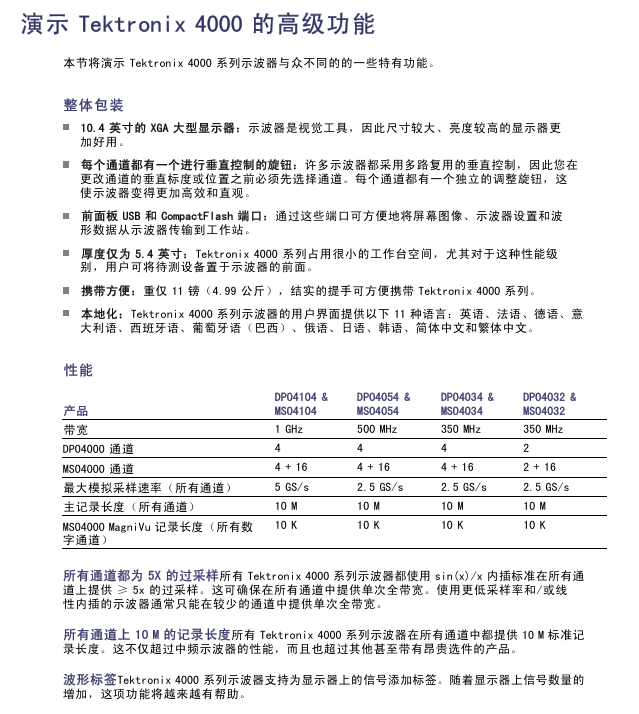
(1) Demo XVI: Setting up digital channels
Step: ① P6516 probe (D0-D6 → CNT OUT 0-6, D7 → CNT CLK, all grounded); ② Default Setup "→ Close channel 1; ③ Set the horizontal "scale" to 200 ns/grid; ④ Press the blue "D15-D0" button (display digital channel, green=high, blue=low); ⑤ Set "height" to "M" (medium); ⑥ Open D7-D0 "(or separately open D0-D7); ⑦ Select D7 from "Trigger Menu" → "Source" → "Menu Off"; ⑧ Channel grouping: Highlight the group marker (inverted triangle), rotate knob b to move the group waveform.
(2) Demo XVII: Threshold for each channel
Operation: Press the blue "D15-D0" button → follow the "Threshold" button below → use the multifunction knob a/b (group/individual setting of channel threshold voltage).
(3) Demo XVIII: Channel Labels
Step: ① Connect the USB keyboard to the oscilloscope; ② D15-D0 "→" Edit Label "; ③ Set labels (Count 0-6) for D0-D6, and use the preset label "CLOCK" for D7; ④ Menu Off.
(4) Demo XIX: Examining Parallel Buses
Step: ① Press B1 → "Bus" and select "Parallel"; ② Define input → Data bits=7 (D0=LSB, D6=MSB); ③ Set "timer data" to "yes", "clock edge"=rising edge, "clock"=D7; ④ "single" acquisition (clock rising edge decoding bus); ⑤ Event Table "(displays data values and timestamps when enabled, can export CSV).
(5) Demo XX: Parallel bus data value triggering
Steps: ① "Trigger Menu" → "Type" Select "Bus" → "Signal Source Bus" Select B1; ② "Data" Set 7F (hexadecimal, all 1s); ③ Menu Off "→" Run/Stop "; ④ Triggered when 7F occurs.
(6) Demo XXI: Searching for Parallel Bus Data Values
Step: ① Press "Search" → "Open"; ② Copy trigger settings to search "(using 7F from demonstration XX as a standard); ③ Change 'data' to 7X (X=any value, resulting in an increase in results); ④ Menu Off.
(7) Demo XXII: Discovery of multi-channel establishment and maintenance
Step: ① P6516 (D2 → Q OUTPUT, D1 → D INPUT, D0 → FF CLOCK, grounded); ② Default Setup "→ Close channel 1; ③ Open D0-D2, label D0="CLOCK"; ④ Set the horizontal "scale" to 1 ns/grid; ⑤ Select "Create&Maintain" from "Trigger Menu" ->"Type"; ⑥ Define input "(clock=D0, D1/D2=data, clock edge=rising edge); ⑦ Set the establishment time to 500 ps and the holding time to 1.5 ns for "time"; ⑧ "single" acquisition (display timing changes, gray fuzzy band=edge uncertainty); ⑨ MagniVu is enabled (to verify if it is a genuine violation).
(8) Demo XXIII: Magnify the white edge
Steps: ① P6139A (channel 1 → XTALK 1, connected to GND), P6516 (D0 → XTALK 1); ② Default Setup "→" Collection "→" Record Length "=1M points; ③ Press "D15-D0" → "Height" to set "L" (large); ④ Set "Auto Settings" → Horizontal "Scale" to 1 μ s; ⑤ Place channel 1 in the upper half and digital channel in the lower half; ⑥ Run/Stop "(observe the white vertical edge); ⑦ Pan/zoom to white edge → zoom in (view narrow pulse details).
Demo board operation and troubleshooting
1. Operation demonstration board
Serial Select button: Switch serial standards (RS232, I2C, SPI, CAN), corresponding LED lights up;
Random Errors button: Generate a random error signal (burr frequency 1-10 ns, duration 500 ns-50 μ s);
SINGLE/HOT ON/OFF button: Switch between single/continuous serial streams;
Single Shot trigger button: Activate 2 ns pulse and 512 MHz oscillator.
2. Troubleshooting of demonstration board
(1) Basic inspection
Power check: Check if the "USB POWER" LED is on. If it is not on, unplug and plug in the USB again;
Set up check: Confirm that the Serial Select LED is consistent with the expected serial standard.
(2) Reset operation
Normal reset: Press the "Reset" button on the demonstration board;
Overall reset: ① Press and hold "SINGLE/HOT ON/OFF"; ② Press and release 'Reset'; ③ Release after all 4 LEDs of Serial Select are fully lit; ④ Four LEDs flash several times, but only the I2C LED lights up (reset completed).
- YOKOGAWA
- Reliance
- ADVANCED
- SEW
- ProSoft
- WATLOW
- Kongsberg
- FANUC
- VSD
- DCS
- PLC
- man-machine
- Covid-19
- Energy and Gender
- Energy Access
- Renewable Integration
- Energy Subsidies
- Energy and Water
- Net zero emission
- Energy Security
- Critical Minerals
- A-B
- petroleum
- Mine scale
- Sewage treatment
- cement
- architecture
- Industrial information
- New energy
- Automobile market
- electricity
- Construction site
- HIMA
- ABB
- Rockwell
- Schneider Modicon
- Siemens
- xYCOM
- Yaskawa
- Woodward
- BOSCH Rexroth
- MOOG
- General Electric
- American NI
- Rolls-Royce
- CTI
- Honeywell
- EMERSON
- MAN
- GE
- TRICONEX
- Control Wave
- ALSTOM
- AMAT
- STUDER
- KONGSBERG
- MOTOROLA
- DANAHER MOTION
- Bentley
- Galil
- EATON
- MOLEX
- Triconex
- DEIF
- B&W
- ZYGO
- Aerotech
- DANFOSS
- KOLLMORGEN
- Beijer
- Endress+Hauser
- schneider
- Foxboro
- KB
- REXROTH
- YAMAHA
- Johnson
- Westinghouse
- WAGO
- TOSHIBA
- TEKTRONIX
- BENDER
- BMCM
- SMC
- HITACHI
- HIRSCHMANN
- XP POWER
- Baldor
- Meggitt
- SHINKAWA
- Other Brands
- UniOP
- KUKA
- IBA
- Beckhoff
-
ADLINK CPCI-6860A - 51-31310-OB10 industrial motherboard CompactPCI SBC
-
ADLINK AmITX-SL-G-H110 - 51-7A104-0A30 Mini-ITX Industrial Motherboard
-
ADLINK PXI-2005-003 - CPCI Industrial PC Data Acquisition Card Multi-Function DAQ
-
ADLINK DININ-814M - 51-14032-0A3D SCSI-100P cable connection Interface Terminal Board
-
ADLINK CPCI-3920NA/C2D15/M1G - 3U CompactPCI Intel Core 2 Duo Single Board Computer
-
ADLINK PCIE-8560 - 51-18014-0A20 Communication Card High Speed DAQ
-
ADLINK PCI-C154+ - Motion Control Card 4-axis Motion Controller Board
-
ADLINK PCI-RTV24 - image capture card Analog Video Frame Grabber
-
ADLINK NuPRO-842LV/P - 51-41360-0B30 Industrial Motherboard CPU Board
-
ADLINK cBP-3208/3208R - CPCI Board 3U 8-Slot CompactPCI Backplane
-
ADLINK PCI-8164 - 4-Axis Motion Controller PCI Card 51-12406-0A40
-
ADLINK PCIe-GIE64+ - 4-CH GigE Vision PoE+ Frame Grabber Video Capture Card
-
ADLINK CPCI-6860 / 6860A - CompactPCI Dual Xeon Single Board Computer
-
ADLINK IEC-915GV - REV 1.1 Industrial motherboard CPU Board
-
ADLINK ND-6520 - Technology RS-232 to RS-422RS-485 Converter NuDAM Module
-
ADLINK RTV-24 / PCI-MP4S - 51-12519-1C30 4-Channel Real Time Video Capture Board
-
ADLINK cPCI-6910 / cPCI-6910AM/M1G - cPCI-6910AM/DXL16/M1G/S80G(G)-3120 BOARD CompactPCI SBC
-
ADLINK NUPRO-A40H - Linghua 51-41807-1A30 Industrial Control Computer Motherboard
-
ADLINK USB-3488A - USB to GPIB INTERFACE USB-3488A(G) Controller Module
-
ADLINK PCI-8134A - motion control card 4-Axis Controller Card
-
ADLINK PCI-7432 - Board 32-Channel input / 32-output Isolated Digital I/O PCI Card
-
ADLINK PCI-8134A - 51-12421-0A10 motion controller card tested
-
ADLINK LPCIe-7230 - 32 CH Isolated Input/output Card 2 Interrupts Low Profile PCIe
-
ADLINK NuPRO-E340 - industrial computer motherboard 51-47807-0A30 PICMG 1.3 SHB
-
ADLINK PCI-7434 - High-speed Digital Acquisition Card 64-CH Isolated DO Card
-
ADLINK NuPRO-E330 - 51-41805-0A20 Indsutrial Board SHB Single Board Computer
-
ADLINK PCI-7248 - OPTO-22 48 CHANNEL DIO DIGITAL TTL/DTL I/O 51-12006-0A40 GP
-
ADLINK PCI-8134 - Motion control card 4-Axis Controller Card
-
ADLINK AMP-208C - Movimiento Control Tarjeta 51-12420-1A20 W/Expansión & Breakout
-
ADLINK PCI-8164 - 51-12406-0A40 PCB Board 4-Axis Motion Controller Card
-
ADLINK DIN-68Y-SGII / DIN-68M-J3A - Terminal Board Connector Interface Block
-
ADLINK PCIe-7432 - Technology 51-18402-0A10 PCIe Card With High Input Range
-
ADLINK PCI-8144 / PCI-8144N - Motion control card 4-Axis Stepper Controller Card
-
ADLINK HSL-HUB3/REPEATER - HIGH SPEED LINK EXTENSION MODULES Distributed Hub Module
-
ADLINK ND-6017 - Data Logging + Acquisition 8CH A/D input Mod NuDAM Module
-
ADLINK LPCIe-7250 - data acquisition card Low Profile 8-CH Relay Output Card
-
ADLINK PCI-7432 - I/O card 64-CH Isolated Digital Input Output PCI Card
-
ADLINK IMB-M43H - industrial control computer motherboard Q87 Chip Micro-ATX
-
ADLINK MP-C154 - Motion control Card 4-Axis Motion Controller Board
-
ADLINK PCI-RTV24 - image capture card Video Frame Grabber Card
-
ADLINK PCI-7250 - 8-CH Relay Output & 8-CH Isolated DI Card
-
ADLINK PCI-6308V - 8-CH 12-Bit Isolated Analog Output PCI Card PCB-I-E-1148=6EX2
-
ADLINK PCI-7248 - capture card 48-CH Opto-22 Compatible DIO Card
-
ADLINK HSL-AI16A02-M-VV - Analog Input Output Distributed Module
-
ADLINK NuPRO-A301 - Rev:1.4 NUPRO-A301 PICMG Full-Size Single Board Computer
-
ADLINK PCI-6208V-GL - 8-CH Voltage Analog Output PCI Card
-
ADLINK PCI-8134A - 51-12421-0A10 4-Axis Motion Controller Card
-
ADLINK MNET-S23 - TECHNOLOGY MNET S23 - SERVO DRIVER CONTROL MODULE
-
ADLINK M-342 - ATX I3 I5 I7 Q67 Industrial Motherboard
-
ADLINK NUPRO-780 - Industrial Motherboard CPU Board PICMG SBC
-
ADLINK MP-C154 / MP-C152 - 4-Axis Motion Control Card Pulse-Train Controller
-
ADLINK NuPRO-935A/LV10B0 - Motherboard 51-41802-0A10 GP w/RAM Industrial Control Board
-
ADLINK MP-C154 - Motion control card 4-Axis Motion Controller Mainboard
-
ADLINK PCI-7250 - PCI Acquisition Card 8-CH Relay Output Isolated DI Card
-
ADLINK ACL-7124 - Technology Inc.24 DIO Card Digital Input Output Card
-
ADLINK PCI-8554 A2 - Timer/Counter Data Acquisition Card
-
ADLINK DIN-825-GP4 - Terminal Block Interface Board Breakout Module
-
ADLINK NuPR0-761 - REV:1.1 Industrial motherboard Full-Size PICMG SBC
-
ADLINK MXE-1401/M8G (G) - Matrix Fanless Embedded Computer Industrial PC
-
ADLINK HSL-DI16DO16-UD-NN - Digital 16 Channel I/O Mod Distributed I/O Module
-
ADLINK ND6520 - NUDAM INTELLIGENT DA&C MODULE RS232-RS-422/RS485 CONVERTOR
-
ADLINK NUPRO-761 - REV:1.1 Industrial Motherboard CPU Board
-
ADLINK AMP-208C - Motion Control Card 51-12420-1A20 DSP-based 8-axis
-
ADLINK NuPRO-A301REV 1.4 - with packaging industrial computer motherboard PICMG SBC
-
ADLINK PCM-9112+ - 51-12300-0A2 industrial motherboard Multi-Function DAQ PC/104 Module
-
ADLINK PCM-7250+ - 8-CH Relay Outputs & 8-CH Isolated DI Module PC/104
-
ADLINK PCI-RTV24 - Image capture card Analog Video Frame Grabber
-
ADLINK PCI-8134 - Motion Controller PCI Card 4-Axis Controller Board
-
ADLINK PCI-7432 - Isolated Digital I/O PCI Card
-
ADLINK PCI-8554 A2 - acquisition card Timer/Counter Card
-
ADLINK PCI-8132 - Rev.A2 2-Axis Servo & Stepper Motion Controller Card
-
ADLINK PCI-8132 - Data Acquisition card 2-Axis Motion Controller Card
-
ADLINK EBP-13E4 - 51-46703-0A30 Industrial Backplane Board Passive Backplane
-
ADLINK PCI-800L - Electronic Card Interface Controller Card
-
ADLINK PCIe-GIE72 - 51-18531-0A10 PCB Board GigE Vision Frame Grabber
-
ADLINK DAQ-2010(G)-OOBO - Simultaneous-Sampling Multi-Function DAQ Card
-
ADLINK PCI-9112 - REV.B1 Multifunction DAQ Card Data Acquisition Card
-
ADLINK PCI-7230 - 51-12003-DA60 32-CH Isolated Digital I/O Card
-
ADLINK PCI-7432 - Data Acquisition Card Isolated Digital I/O PCI Card
-
ADLINK ETX-AT-N270-18/LXE - 51-71111-0A20 ETX CPU Module Motherboard
-
ADLINK HSL-DI32-UD-N - DIGITAL INPUT 32 POINTS MODULE Distributed I/O
-
ADLINK AMP-204C - Motion Control card DSP-Based 4-Axis Advanced Controller
-
ADLINK MNET-4XMOG-0050 - Four-axis Motion Controller Distributed Motion Module
-
ADLINK AMP-204C - Motion control card DSP-Based 4-Axis Pulse-Train Controller
-
ADLINK PCI-7442 - Switch card 64-Channel Datalogging & Acquisition Card
-
ADLINK M-302 - Industrial control motherboard ATX PC Board
-
ADLINK NUPRO-852 / NUPRO-852LV - Industrial motherboard Single Board Computer
-
ADLINK PCI-8134 - REV.B1. 4-Axis Motion Controller Card
-
ADLINK PCI-GIE62 + - 51-18502-0A20 2-CH GigE Vision Frame Grabber PoE Card
-
ADLINK PCI-MPG24 - 51-12523-0B20 MPEG4 Card Video Compression Hardware
-
ADLINK HSL-TB32-M-DIN - 32-CH I/O TERMINAL W/ HSL-AI16AO2-M-VV MODULE
-
ADLINK PCI-M114-GL - PCB Ver 2.1 Motion Controller Axis Card
-
ADLINK IMB-M40H - SYM76996H61 motherboard Industrial Computer Mainboard
-
ADLINK NUPRO-A40H - 51-41807-1A20 industrial control motherboard H61 Chip
-
ADLINK PCI-M114-GL - Axis Card Data Acquisition Card PCB VER2.2 Motion Controller
-
ADLINK PCI-8134 - Motion Controller PCI Card 4-Axis Controller Board
-
ADLINK PCI-8102 - Motion control card 2-Axis Servo & Stepper Controller
-
ADLINK NuPRO-841REV:3.0 - motherboard Industrial Control PC Board
-
ADLINK HSL-TB32-U-DIN REV A1 - Breakout Terminal Board Field I/O Module
-
ADLINK AMP-204C - Motion Control card DSP-Based 4-Axis Pulse-Train Controller
-
ADLINK NUPRO-A40H - 51-41807-1A20 industrial control motherboard H61 PC Board
-
ADLINK PCI-6308A / PCI-6308V - 51-12202-0A50 Isolated Analog Output Card
-
ADLINK AMP-204C - DSP-Based 4-Axis Advanced Pulse-Train Motion Controller
-
ADLINK PCI-7434 - Technology 64-Channel Isolated Digital I/O PCI Cards
-
ADLINK CPCI-6840 / CPCI-6840V / PM16/M1G-12G0 - CompactPCI Single Board Computer CPU Module
-
ADLINK PCIE-GIE74 - Motherboard Video Capture Card 51-18531-0A10 Frame Grabber
-
ADLINK NuPRO-E330 - industrial computer equipment motherboard Control Mainboard
-
ADLINK AMP-208C / 51-12420-1A20 - Motion Control Card W/ Expansion & Breakout Board
-
ADLINK HPCI-14S12U - industrial computer baseboard Passive Backplane 14 Slots
-
ADLINK PCI-8164 - 4-Axis Motion Controller PCI Card W/ 1x Cable, 1x Breakout Box
-
ADLINK PCIe-RTV24 - 51-18016-0A20 Image Acquisition Video Capture Card
-
ADLINK M-342 - 5 PCI ATX Motherboard Industrial PC Mainboard
-
ADLINK PCI-FIW64 - 4/2 Channel IEEE1394B Image Capture Card FireWire Frame Grabber
-
ADLINK PCI-7432 - digital IO card 64-CH Isolated Digital Input Output Card
-
ADLINK 51-12001-0C20 - Circuit Board PCI-7200 Data Acquisition Controller Card
-
ADLINK PXI-3920 - PXI 3U cPCI Industrial Controller Embedded System CPU Board
-
ADLINK NuPRO-841REV:2.0 - motherboard Industrial Control PC Board
-
ADLINK NuPro-E330 - 51-41805-0A20 PCB Industrial Control Computer Motherboard
-
ADLINK PCI-RTV24 - Image capture card Analog Video Frame Grabber
-
ADLINK PCI-7442 - Switch card 64-Channel Datalogging & Acquisition Card
-
ADLINK HPX-13S4 - device baseboard Passive Backplane Riser Card
-
ADLINK PCI-9112 REV A.1 - Multi Function DA&C Board Data Acquisition Card
-
ADLINK PCI-7248 - 51-12006-0A40 Card Control 48-CH Digital I/O Module
-
ADLINK CPCI-6860 / 6860A - motherboard CompactPCI Dual Xeon Single Board Computer
-
ADLINK DPAC-3020-11(G) - Embedded PC Automation Controller Machine Control Board
-
ADLINK NuPRO-841 REV:1.0 - industrial control motherboard CPU Board
-
ADLINK MNET-4XMOG-0050 - Four-axis Motion Controller MNET Motion Control Card
-
ADLINK ETX-AT-N270-18/LXE - 51-71111-0A20 ETX CPU Module Motherboard

K-JIANG

Add: Jimei North Road, Jimei District, Xiamen, Fujian, China
Tell:+86-15305925923