
K-WANG


YASKAWA U1000 series 24V power supply options (PS-U10L/PS-U10H)
YASKAWA U1000 series 24V power supply options (PS-U10L/PS-U10H)
Core Overview
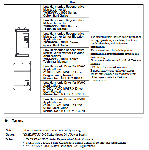
This document is the installation manual for the Yaskawa U1000 series 24V power supply option (model PS-U10L/PS-U10H), which mainly introduces the functions, driver adaptation, installation process, operation verification, and safety specifications of the option. It provides users with full process guidance from receiving inspection to after-sales support, and is suitable for professional installation and maintenance personnel.
Core parameters and adaptation range of options
1. Option model and function definition
Model identification: This option includes two models - PS-U10L and PS-U10H, with the name "24V Power Supply" clearly indicating its core function: to provide a separate 24V DC power supply for the control circuit when there is no power supply for the main circuit of the drive, only supporting power supply for the control circuit, and unable to supply power to the main circuit of the drive 🔶 2-5 🔶 2-8 🔶 2-89.
Core purpose: With this option, users can access network communication, navigate digital operators, read I/O data, and view fault/parameter data while the main power is disconnected; If parameters need to be modified, the driver parameter o2-19 (UV state parameter writing selection) must be set to "1 (enabled)", otherwise the parameters cannot be modified even if the control circuit is powered on 🔶 2-91.
2. Adapt to the driver model and software version
According to document table 1 (Compatible Drive Models), the compatibility relationship between options and drives is as follows:
Option Model Adaptation Driver Series Driver Model Identification (Key Characters) Remarks
PS-U10L U1000, U1000L, Z1000U models containing "2" (such as CIMR-U 2 , CIMR-Z 2 ) require the driver software version to meet the standard
PS-U10H U1000, U1000L, Z1000U models containing "4" (such as CIMR-U , CIMR-Z 4 ) require the driver software version to meet the standard
The specific software version requirements are: U1000 series requires S5171, S1017 and above; U1000 crane specific models require S6412 and above; U1000L series requires S6213 and above. If the driver version is not met, it may cause the option to not work properly 🔶 2-96.
3. Key specifications and certification of options
On page 42 of the document (Table 4 Option Specifications), specify the technical parameters of the options and indicate the safety certification standards they comply with:
Electrical parameters: Input working voltage 24Vdc ± 20% (range 19.2V-28.8V), input current 1.9A, power consumption 38W, output holding time exceeding 50ms after power failure;
Environmental parameters: Operating temperature -10 ℃~+50 ℃ (14 ℉~122 ℉), short-term transportation and storage temperature -20 ℃~+60 ℃ (-4 ℉~140 ℃), weight 0.2kg (0.4lbs.), installation environment needs to match the specifications of the drive environment 🔶 2-431;
Certification standards: Compliant with UL (USA/Canada) and CE (Europe) certifications, with UL certification based on UL508C standard and CE certification in accordance with the Low Voltage Directive (2006/95/EC) and EMC Directive (2004/108/EC), following harmonized standards such as IEC/EN 61800-5-1 and EN 61800-3 🔶 2-431 🔶 2-499.
Detailed explanation of the entire installation process (including preparation, steps, and requirements)
1. Receipt inspection and installation preparation
(1) Receiving inspection items
After receiving the option, the user needs to complete three core checks: 1 Check if the appearance of the option is damaged during transportation. If damaged, immediately contact the transportation company (Yaskawa warranty does not include transportation damage); 2. Check if the option model is consistent with the order (refer to Figure 3 in the document for the location of the model identification); 3. Confirm that the packaging contents are complete, and the specific list is as follows 🔶 2-103 🔶 2-104 🔶 2-105,:
Item name, quantity, and purpose
Signal/power transmission between one option connecting cable and the driver
M3 screws with 3 options for fixation (some installation methods require the use of screws)
The installation method of the six parts of the stud (such as C, D, E, F) includes option fixing
6 zip ties for organizing cables to avoid clutter or pressure
Installation Manual (TOBPC73060095. pdf) 2 copies of technical guidance (including both Chinese and English versions)
Option body (PS-U10L/PS-U10H) 1 core functional component
If you receive an incorrect model or option that does not work properly, you need to contact the supplier for assistance.
(2) Essential Tool List
The document clearly lists the required tools and specifications for installation. Missing or using non compliant tools may result in installation failures:
Cross screwdriver: M4 metric specification, or # 1, # 2 American standard specification, used for disassembling/installing drive cover screws;
One letter screwdriver: blade thickness 0.4mm, blade width 2.5mm, used for wiring operation of option terminal block TB1;
Wire stripping pliers: used to strip the insulation layer of cables to ensure good contact between the wiring terminals;
Wrench: Open end wrench, ring wrench or ratchet wrench (diameter 6mm), used to tighten bolts, the tightening torque should be controlled at 0.5-0.7N · m 🔶 2-109;
Attention: The document does not include cable pre-processing tools (such as crimping pliers), and users need to prepare them themselves.
2. Classification of installation methods and operating steps
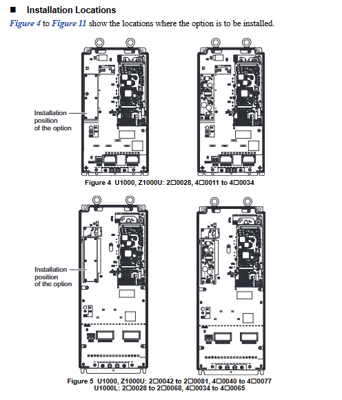
The document categorizes installation methods into six types, A-F, based on the differences in drive models. The core differences lie in the option fixing method (only screws/screws+studs), cable connection interface (CN1 direct connection/CN19 adapter), and installation position. The following are the key information and general steps for each type of method:
(1) Installation method classification and driver adaptation
Installation method: Adapt to driver model (example) Fixed method: Cable connection interface corresponds to document page number
A U1000 2 0028-2 0081, 4 0011-4 0077; U1000L 20028-20068; Z1000U 2 0028-2 0081 M3 screw option only, CN1 direct connection to driver reserved interface 22
B U1000 2 0104, 2 0130, 4 0096, 4 0124; U1000L 2 0081, 2 0104; Z1000U 2 0104, 2 0130 only M3 screw option CN1 direct connection to driver reserved interface 25
C U1000 2 0154, 2 0192, 4 0156, 4 0180; Z1000U 2 0154, 2 0192 screw+stud option CN1 connected to driver CN19 28 via cable A
D U1000 2 0248, 4 0216, 4 0240; Z1000U 2 0248, 4 0216 screw+stud options CN1 connected to driver CN19 31 via cable B
E U1000 40302-40414; Z1000U 4 0302-4 0414 screw+stud option CN1 connected to driver CN19 34 via cable C
F U1000 4A0477-4A0930; Z1000U 4A0477-4A0930 screw+stud option CN1 connected to driver CN19 37 via cable B
(2) General installation steps (taking method A as an example, differences in other methods have been marked)
Power off and discharge: Disconnect all power sources from the drive, wait for the internal capacitor to discharge (at least 5 minutes until the CHARGE indicator light on the drive goes out), confirm that there is no dangerous voltage, and then remove the digital operator (F), front cover (E), and terminal cover (G). The removal steps should refer to the manual provided with the drive;
Option fixing: Use the M3 screw inside the package to fix the option in the designated position of the driver (refer to Figure 4 in the document for the position), ensuring that it is firmly fixed and not loose;
Cable connection: Pull out the loose end of the reserved connection cable for the driver, insert it into the CN1 interface of the option, pay attention to the interface direction, and reverse insertion may damage the connector or driver;
Cover plate reset: Reinstall the driver front cover, terminal cover, and digital operator to ensure that the cables are not squeezed by the cover plate and to avoid insulation layer damage causing short circuits;
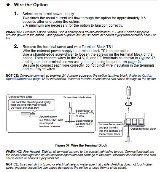
External power supply wiring: Go to the "Wire the Option" section on page 40 of the document and connect an external 24V power supply to the option terminal block TB1 (terminal definition: 24=+24VDC input, 0=0V, FE=ground). The wiring steps are as follows:
Loosen the TB1 terminal screw with a straight screwdriver;
Peel off the insulation layer of the cable (with a bare length of about 5.5mm, to avoid the wire ends from unraveling);
Insert the cable into the corresponding terminal and tighten the screw (torque 0.22-0.25N · m);
Wrap the cable shielding layer with heat shrink tubing or electrical tape to avoid short circuits caused by contact with other circuits 🔶 2-393;
(3) Special installation requirements (for C-F method)
Fixed difference: The C-F method requires the installation of screws (tighten with a 6mm wrench, torque 0.5-0.7N · m) first, and then fix the option with screws;
Cable differences: C method uses connection cable A, D/F method uses connection cable B, E method uses connection cable C, and the cables need to be sorted according to the document diagram (such as Figure 23, 27) and fixed with zip ties to avoid cable entanglement or compression.
3. Key wiring specifications
Power requirements: The external 24V power supply must be UL Listed Class 2 certified (or equivalent) to avoid the risk of electric shock or fire caused by the use of non certified power supplies. The power supply must be able to provide at least 3A current (the instantaneous current when the option is powered on is twice the conventional value, lasting for about 0.5 seconds);
Cable specifications: Shielded twisted pair cables are required for control cables, with a recommended wire diameter of 0.75mm ² (18AWG). The suitable wire diameter range for single strand cables is 0.25-1.5mm ² (24-16AWG), and the suitable wire diameter for crimping terminals is 0.25-0.5mm ² (24-20AWG);
Shielding treatment: The cable shielding layer needs to be grounded at one end (connected to the driver grounding terminal) to avoid circulating current caused by double ended grounding, and the grounding area should be as large as possible (refer to Figure 40 in the document);
Operation verification and troubleshooting
1. Run verification steps
After installation and wiring are completed, the following steps should be taken to verify whether the option functions properly:
Power on the main circuit of the driver and confirm that the external 24V power supply has been connected to the TB1 terminal of the option, and that the option is properly connected to the driver cable;
Disconnect the power supply of the main circuit of the drive, and the option should supply power to the control circuit of the drive;
Observe the red LED indicator light on the option. If it lights up, it indicates that the option is working properly;
When checking the digital operator of the drive, it should briefly display "Fdv" or "AUv" (undervoltage prompt) for about 10 seconds. This prompt is a normal phenomenon, indicating that the control circuit has been powered through the option 🔶 2-413;
2. Handling of abnormal situations
If the option LED does not light up: check if the external 24V power supply is normal (voltage range 19.2-28.8V), if the TB1 terminal wiring is loose or reversed, and if the option is in good contact with the driver cable;
If there is no "Fdv/AUv" prompt on the operator: first confirm that the wiring is correct, then check if the driver parameter o2-19 is set correctly. If it is still abnormal, it may be a problem with the option or driver, and contact Yaskawa after-sales service;
In addition, Table 3 (Power Supply and Control Circuit) of the document specifies the operation of the control circuit and driver under different power states, which can be used to assist in fault diagnosis:
Driver main circuit power options, power supply status, driver control circuit operation status, driver operation possibility
ON, ON, can run normally
ON/OFF can run
OFF/ON can access data (parameters/faults) but cannot run
OFF: Stop running and cannot run
Core Security Standards
(1) Electrical safety
Prohibited live operation: During installation, wiring, and maintenance, all power sources must be disconnected and the capacitor must be discharged (at least 5 minutes). The CHARGE light must be turned off before operation, otherwise it may cause electric shock death or serious injury 🔶 2-133;
Authorization operation requirements: Only authorized personnel who have received training are allowed to install and maintain. Unauthorized personnel operation may cause safety accidents;
Prohibited from modifying equipment: It is not allowed to modify the driver body or option circuit without authorization. Modifying will result in the expiration of the warranty, and Yaskawa will not be responsible for any damage caused by this;
(2) Fire prevention and equipment protection
Terminal torque requirements: All terminal screws must be tightened to the specified torque (such as TB1 terminal 0.22-0.25N · m, screw 0.5-0.7N · m). Too loose may cause poor contact, heat generation, and fire, while too tight may damage the terminals 🔶 2-149;
Static electricity protection: When in contact with options, drivers, or circuit boards, it is necessary to follow the ESD (electrostatic discharge) protection process (such as wearing an anti-static wristband) to avoid static electricity damaging the circuit;
Environmental restrictions: It is prohibited to expose options or drivers to halogen disinfectants, and they should not be stored in fumigated wooden packaging to avoid chemical damage to electrical components
- YOKOGAWA
- Reliance
- ADVANCED
- SEW
- ProSoft
- WATLOW
- Kongsberg
- FANUC
- VSD
- DCS
- PLC
- man-machine
- Covid-19
- Energy and Gender
- Energy Access
- Renewable Integration
- Energy Subsidies
- Energy and Water
- Net zero emission
- Energy Security
- Critical Minerals
- A-B
- petroleum
- Mine scale
- Sewage treatment
- cement
- architecture
- Industrial information
- New energy
- Automobile market
- electricity
- Construction site
- HIMA
- ABB
- Rockwell
- Schneider Modicon
- Siemens
- xYCOM
- Yaskawa
- Woodward
- BOSCH Rexroth
- MOOG
- General Electric
- American NI
- Rolls-Royce
- CTI
- Honeywell
- EMERSON
- MAN
- GE
- TRICONEX
- Control Wave
- ALSTOM
- AMAT
- STUDER
- KONGSBERG
- MOTOROLA
- DANAHER MOTION
- Bentley
- Galil
- EATON
- MOLEX
- Triconex
- DEIF
- B&W
- ZYGO
- Aerotech
- DANFOSS
- KOLLMORGEN
- Beijer
- Endress+Hauser
- schneider
- Foxboro
- KB
- REXROTH
- YAMAHA
- Johnson
- Westinghouse
- WAGO
- TOSHIBA
- TEKTRONIX
- BENDER
- BMCM
- SMC
- HITACHI
- HIRSCHMANN
- XP POWER
- Baldor
- Meggitt
- SHINKAWA
- Other Brands
- UniOP
- KUKA
- IBA
- Beckhoff
- ADLINK
-
Beckhoff CX1100-0910 - Power Supply Module
-
Beckhoff C5210-0010 - Communication Module C5210
-
BECKHOFF KL1352 - Bus Terminal SET OF 2 FREE FAST SHIP
-
Beckhoff EL3058 - 8 x analog input single ended 4...20mA 85惟 shunt 12bit
-
Beckoff CX1100-0920 - UPS Module 24VDC (US SELLER) * *
-
BECKHOFF C6920-0000 - C69200000 PLC Moudule
-
Beckhoff CX5120-0115 - CPU controller module CX5120-0115
-
Unknown 15F5C1E-Y50A - Of Frequency Converters
-
Beckhoff AX5118-0000-0200 - Servo Drive HTP0
-
BECKHOFF AX5106-0000-0200 - Servo Drive
-
Beckhoff CX5240-0175 - Module (free) #U2327D YG
-
Beckhoff CP6607-0001-0000 - Compact PC Panel Economy Installation Operator 5,7 "
-
Beckhoff EP3744-0041 - 2022 EP37440041 Module
-
Beckhoff CP6209-0001-0020 - 6.5" PC Touch Screen Control Panel 24VDC
-
Beckhoff CX9020-0111 - /U900 +8x+2xEL3121+1x EL9410+3xEL1008+1x EL2008 Set
-
Beckhoff C6525-1030-0050 - Industrial PC
-
Beckoff CX1100-0920 - UPS Module 24VDC (US SELLER)
-
Beckhoff CX5010-0120 - CX5010 Processor Intel Atom Z510 B24
-
Siemens 6FC5203-0AF04-1BA1 - Operation Panel
-
Beckhoff CX5230-0175 - / 000029724 Embedded PC / Industrial PC on Rail
-
Beckhoff CP3916-0000 - industrielles Anzeige- und Bedienterminal
-
BECKHOFF CX1500-M310 - CX1000-N000 CX1000-0011 CX1000-C00L CX1100-0002 PLC Module
-
Beckhoff EL1872 - 16-channel digital input terminal
-
BECKHOFF EP2318-0001 - module
-
Beckhoff CX9020-0110 - Basic CPU Module
-
Beckhoff EL2564 - EtherCAT Terminal, 4-channel LED output, 5鈥?8VDC, 4A, RGBW
-
Beckhoff CX5130-0155 - /000105637 Automation Embedded PC
-
B&R 400 - Power Control Panel Rev D0 24 VDC
-
Beckhoff CX2020-0155 - module
-
Beckhoff CX9020-0115 - PLC Module
-
BECKHOFF EL6695 - PLC EL 6695
-
BECKHOFF EL7047 - PLC Modules
-
Beckhoff CX1000-0012 - Control HW 2.2 + CX1500-M310 + CX1000-C00L + CX1100-0002+
-
Beckhoff C6920-1039-0030 - control cabinet industrial PC CPU Celeron 1.90 GHz, 2 cores
-
BECKHOFF CX1100-0910 - PLC Module#
-
Beckhoff IL2301-B318-0000 - Coupler Box 4 Channel Digital Input |
-
Beckhoff CX7080 - Module
-
Beckhoff C6930-0060 - Industrial PC
-
Beckhoff CP7902-1060-0000 - Touchscreen 15 " CP7902
-
beckhoff CX9020-0111 - Controller module or UPS
-
Beckhoff CX8091 - PLC Module CX8091
-
Beckhoff C6640-1008-0030 - Control Cabinet Industrial PC
-
BECKHOFF CX1100-0920 - module
-
Beckhoff C9900-M921 - see pictures
-
BECKHOFF CP6829-0001-0000 - Touch Panel
-
BECKHOFF C6930-0060 - Industrial Computer
-
BECKHOFF CX8050 - PLC module
-
Beckhoff CP6202-0021-0020 - Touch Screen #
-
BECKHOFF AM3031-0C20-0000 - SERVO MOTOR
-
Unknown BCH1302N11A1C - Servo motor
-
Beckhoff EL2502 - 2-channel pulse width output terminal
-
Beckhoff EL6731 - Profibus Master / *Rev: 0025
-
Beckhoff CP3918-0010 - Control Panel
-
BECKHOFF CP2915-0010 - [24 MONTH WARRANTY] Control Panel
-
Beckhoff AX5203-0000-0202 - Servo Drive
-
Schneider TSXDSY64T2K - PLC OUTPUT MODULE
-
Beckhoff EP4174-0002 - Module-
-
Beckhoff IL2302-B318-0000 - Profibus Box
-
Beckhoff CP6709-0001-0000 - Touchpanel
-
BECKHOFF CX2030-0123 - Controller
-
Beckhoff CX9020-0111 - Processor Module
-
Beckhoff CX1020-0000 - CX Basic CPU Module
-
Beckhoff AX2003-AS - Servo Drive HTP0
-
Beckhoff C6240-1052-0040 - 4-086-06-3073 Industrial Computer CB1052-0003
-
Beckhoff EL1918 - 8 xTwinSAFE Input
-
Beckhoff AM8072-0R20-0000 - Servomotor
-
BECKHOFF AM8021-1B21-0000 - servo motor #T882 YS
-
Beckhoff EL6224 - 4 X Terminal IO-LINK
-
Beckhoff CX5140-0135 - embedded PC with Intel Atom processor 4 GB HW 3.6
-
Beckhoff CP7201-1000-0000 - Panel PC #
-
Beckhoff CX5130-0121 - Embedded-PC 4GB CPU Module HW 2.5 Industrial PC
-
Beckhoff AM8022-0D41-1002 - Servomotor
-
BECKHOFF CX2030-0130 - Module
-
BECKHOFF EL1872 - 16-channel digital input terminal
-
Unknown GXMMW.A203P33 - 1pc encoder
-
Beckhoff EL6631-0000 - EtherCAT Terminal 2-Port EL 6631
-
BECKHOFF C6925-0030 - Industrial Computer
-
Beckhoff CX8190 - A Module
-
BECKHOFF CX2040-0135 - CX2040-0135/000000927 CPU BASE MODULE i7 2715QE 2.1GHz --
-
BECKHOFF KL6023-0000 - Wireless adapter
-
Saia Burgess PCD7.F700 - PCD7F700 Communication Module
-
Beckhoff CX5130-0112 - CPU Module
-
BECKHOFF CX1020-N010 - CX1020-N000 CX1020-0111 CX1100-0004 EL2008 EL3064 EL4004
-
Beckhoff EP1819-0021 - A Module
-
Beckhoff CX2030-0120 - / 4gb with CX2100 0004
-
B&R X20-XC-0292 - Automation Powerlink Ethernet Bus Controller Module
-
Beckhoff BK3110 - One PLC Module
-
BECKHOFF KL3222 - PLC Module
-
BECKHOFF CX1500-M310 - CX1000-N000 CX1000-0011 CX1000-C00L CX1100-0002 PLC MODULE
-
Beckhoff CP3918-0010 - Control Panel
-
Beckhoff CX2030-0100-1002 - /4GB + CX2100 + CX2550 + CX2500-0060 + SSD
-
Beckhoff EP1816-0008 - PLC Module
-
Beckhoff CX5130-0112 - Module
-
Beckhoff Cx1500-m750 - CPU Hw: 1.4
-
BECKHOFF AX5112-0000-0200 - AX511200000200 Servo Driver
-
Beckhoff EL3751 - EtherCAT Terminal 1 Channel Analog Input Multifunction 24 Bit
-
Beckhoff CX1100-0002 - Power Supply Module
-
Beckhoff CP3916-1016-0010 - Control Panel
-
BECKHOFF CX9001-1101 - #NAME?
-
Beckhoff EP3174-0002 - EtherCAT Box Module
-
Beckhoff C6030-0070 - servo drive
-
Beckhoff CX2020-0120 - /4GB CPU, CX2100-0904, 3x EL6900, EL1904, 16GB Memory
-
BECKHOFF C6110 - BOX-PC 113608
-
BECKHOFF EK1914 - module #P
-
Beckhoff C6140 - Ipox IP-4GVI63 + CH7009A_DVI_TV + SIEMENS A5E00369843 + WD800AAJB
-
Beckhoff CX5020-0111 - controller Good quality
-
BECKHOFF C6015-0010 - / 6559380 ULTRA-COMPACT INDUSTRIAL PC ()
-
Beckhoff AX5203-0000-0200 - PLC module
-
Beckhoff EL2872 - 16-channel digital output terminal
-
BECKHOFF C3640-0000 - Panel Industrial PC 100/240VAC 128MB E0122L
-
Beckhoff CX8031 - Module
-
Beckhoff CX5020-0120-1002 - PLC module#
-
Beckhoff C6140 - M845B + SIEMENS A5E00369843 + C9900_A159_1 + AUTOMATA CAN PCI 1N
-
BECKHOFF AX5112-0000-0200 - Servo Drive*ie
-
B&R ECPA42-01 - Analog Output Module 4-Channel, +/- 10V Output Signal, 20mA Max
-
Beckhoff EL6631-0010 - PLC Module
-
BECKHOFF C6930-0070 - CONTROL CABINET INDUSTRIAL PC
-
BECKHOFF AX5112-0000-0200 - AX511200000200 Servo Driver
-
BECKHOFF EK9000 - Programmable Logic Controller Module EK9000 EK9000
-
BECKHOFF C6920-1028-0000 - Industrial computer
-
Beckhoff CX2030-0120 - controller Module
-
Beckhoff BX8000-0000 - Bus Terminal Controller HW 4.4
-
B&R 3NC154.60-2 - Positioning Module#
-
BECKHOFF CX1020-0122 - PLC module
-
Beckhoff AM3032-0D40-0000 - Servo Motor
-
BECKHOFF CX5020-0111 - CPU Module CX5020-0111
-
Beckhoff CB1051 - G5 Motherboard
-
BECKHOFF KL2641 - 1-channel relay output terminal

K-JIANG

Add: Jimei North Road, Jimei District, Xiamen, Fujian, China
Tell:+86-15305925923