
K-WANG


YASKAWA AC Drive G7 Series (Model CIMR-G7U)
YASKAWA AC Drive G7 Series (Model CIMR-G7U)
Basic Information and Security Core Guidelines
1. Positioning
The core technical document of the G7 series communication drive (model CIMR-G7U) covers the entire lifecycle of product safety specifications, model specifications, installation and wiring, operation modes, parameter settings, trial operation and maintenance, troubleshooting, etc. The target audience is trained authorized personnel (installers, maintenance engineers, etc.) who must strictly follow the manual guidance to ensure the safe and stable operation of the equipment.
2. Core security standards that cannot be violated
(1) Electrical safety
The iron rule for power-off operation: Before wiring, removing the cover plate (terminal cover, front cover), and touching the circuit board, all power sources must be disconnected, and the internal capacitor must be discharged (at least 5 minutes until the CHARGE indicator light goes out). After the discharge is completed, the DC bus voltage (below 50Vdc) must be measured to confirm safety and avoid electric shock.
Prohibited live operation: It is strictly prohibited to connect/disconnect wires, plug and unplug digital operators with live power, and it is forbidden to remove the protective cover when the power is turned on, otherwise it may cause electric shock or equipment short circuit.
Power matching requirements: Before powering on, it is necessary to confirm that the rated voltage of the driver is consistent with the input power supply (200-240V level/380-480V level), otherwise it may cause a fire or equipment burnout.
(2) Equipment protection and operation restrictions
Prohibition of modification and withstand voltage testing: It is not allowed to modify the driver body or circuit without authorization (modification will directly result in warranty failure), and no component shall be subjected to withstand voltage testing - the equipment contains sensitive semiconductor devices, and high voltage can cause irreversible damage.
Output terminal limitation: The output terminals (U/T1, V/T2, W/T3) must not be connected to AC power, phase-shifting capacitors, LC/RC noise filters, or electromagnetic contactors (closing the contactor during operation will generate surge current, triggering overcurrent protection) 、 .
Static electricity protection: When in contact with the control board or CMOS IC, it is necessary to follow the ESD (electrostatic discharge) process (such as wearing an anti-static wristband) to avoid static electricity damaging the circuit.
Product Model and Receipt Confirmation
1. Model system and specification classification
The G7 series drivers are divided by voltage level and protection type, covering different power requirements. The core parameters are as follows:
Classification dimension specific specification remarks
Voltage level 200-240V (3-phase): maximum motor capacity 0.4kW-110kW; 380-480V (3-phase): 0.4kW-300kW. In the model, "2" represents the 200-240V level, and "4" represents the 380-480V level (such as CIMR-G7U20P4 which has a 200V level of 0.4kW)
Protection type open enclosure (IEC IP00): to be installed inside the control cabinet; Enclosed wall mounted (IEC IP20/NEMA 1): can be directly wall mounted. Enclosed type requires the installation of a top protective cover to meet IP20 requirements
Output capacity of 200V level: 1.2kVA (0.4kW) -160kVA (110kW); 480V level: 1.4kVA (0.4kW) -460kVA (300kW) requires matching motor rated capacity (recommended 50% -100% driver capacity)
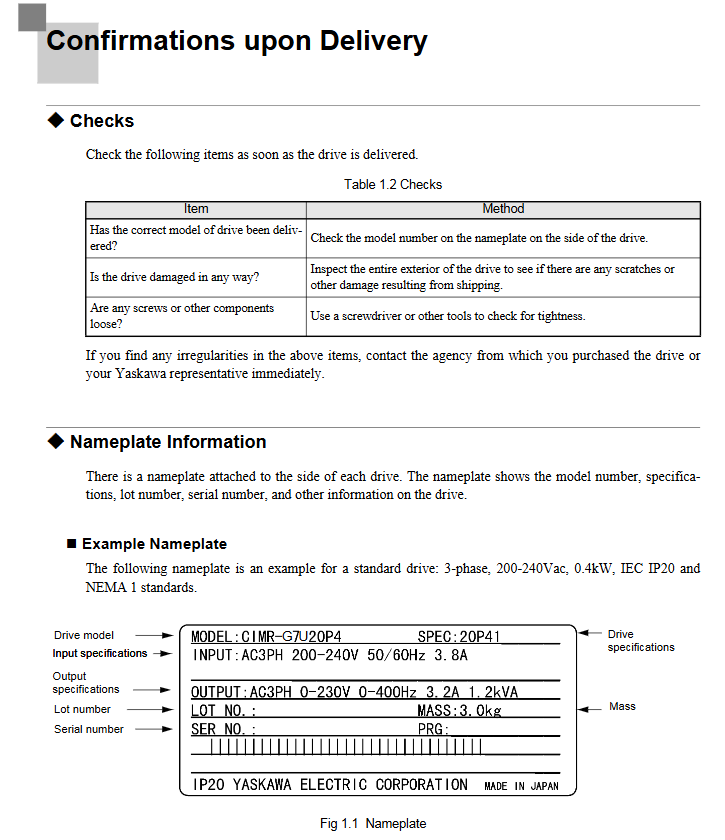
2. Receipt inspection and preparation
(1) Must check items
Model and appearance: Verify that the packaging label model matches the order, check that the drive housing is free of collisions or scratches, that the terminals are not deformed, and that the digital operator is not damaged.
Component integrity: Confirm that the packaging contains the driver body, digital operator, terminal cover, fixing screws (M3/M3.5, etc.), and installation manual (1 copy in both Chinese and English). If missing or damaged, immediately contact the supplier.
(2) Preparation before installation
Tool list: Cross screwdriver (M4/# 1/# 2), straight screwdriver (blade thickness 0.4mm/blade width 2.5mm), wire stripping pliers, 6mm wrench (tightening torque of 0.5-0.7N · m for bolts), wire crimping pliers (for crimping terminals).
Environmental confirmation: The installation surface should be made of non combustible materials such as metal, kept away from oil mist, dust, radioactive substances, and corrosive gases. The environmental temperature/humidity should meet the requirements (open type: -10~+45 ℃, ≤ 95% RH; closed type: -10~+40 ℃, ≤ 95% RH).
Full process specification for installation and wiring
1. Key installation requirements
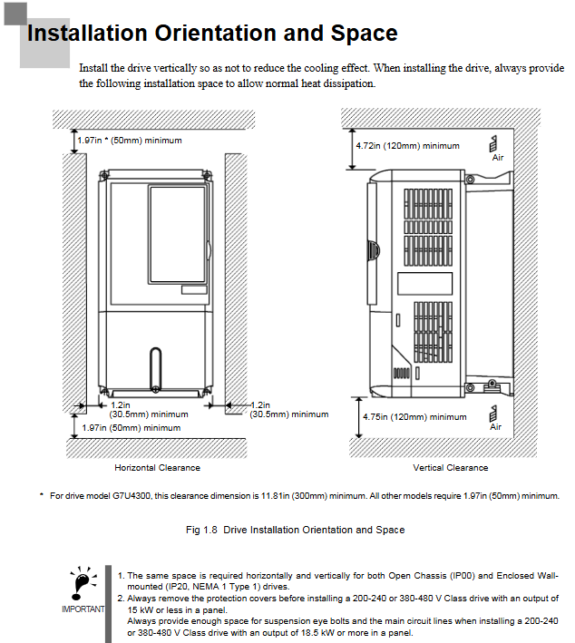
(1) Installation location and space
Installation direction: It must be installed vertically to avoid horizontal or inclined installation (which will reduce heat dissipation efficiency and cause overheating).
Cooling space: A minimum space of 50mm in the horizontal direction and 120mm in the vertical direction should be reserved for single installation. When multiple units are installed side by side, if the spacing is insufficient, a cooling fan or air conditioner should be installed in the control cabinet to ensure that the inlet air temperature is ≤ 45 ℃.
Special note: For models of 18.5kW and above, space for eyebolts and main circuit cables must be reserved. For enclosed installations of 15kW and below, top/bottom protective covers must be removed to meet heat dissipation requirements.
(2) Dismantling and resetting of cover plate
Terminal cover disassembly: Low power models (20P4-2015/40P4-4015): Loosen the bottom screws, press both sides and lift them up 30 ° before removing them; High power model (2018-2110/4018-4300): Loosen the top left and right screws, pull out and lift up.
Disassembly of digital manipulator: Press the side buckle of the manipulator and lift it up to remove it. When installing, the front cover should be installed first before installing the manipulator to avoid poor contact and malfunction.
2. Wiring specifications (main circuit+control circuit)
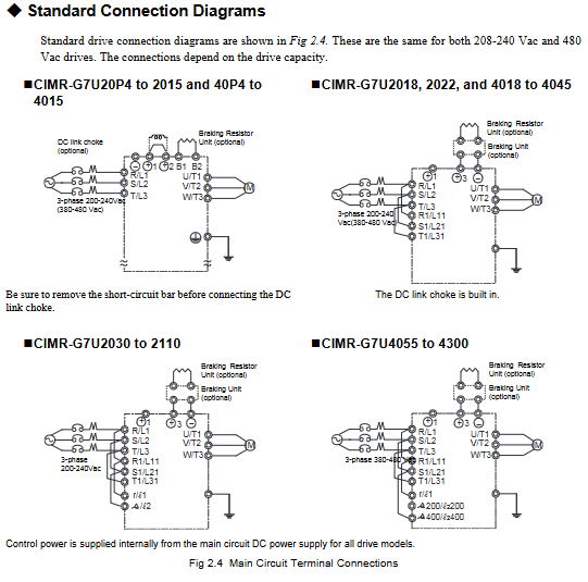
(1) Main circuit wiring
Cable specifications: Select the appropriate cable according to the model (for example, 2mm ² (14AWG) cable is recommended for the main circuit of the 200V level 0.4kW model, and 325mm ² cable is required for the 480V level 300kW model), using UL certified copper wire (75 ℃ temperature resistance).
Terminal torque: The torque of different terminal screws varies, such as M4 screws with a torque of 1.2-1.5N · m and M8 screws with a torque of 9.0-10.0N · m. Loosening can easily cause heating and fire, while tightening can easily damage the terminals.
Grounding requirements: The grounding resistance for 200V level should be ≤ 100 Ω, and for 480V level it should be ≤ 10 Ω. The grounding cable should be independent (not shared with welding machines or power tools) and the length should be as short as possible. Multiple drivers should be grounded to avoid forming loops.
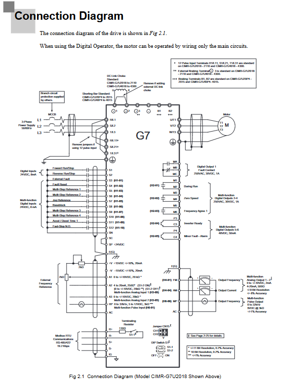
(2) Control circuit wiring
Cable requirements: Use shielded twisted pair cables (recommended 0.75mm ²/18AWG), separate them from the main circuit cables (spacing ≥ 30cm), and connect the shielding layer to the driver grounding terminal (E (G)).
Terminal function: The digital input terminals (S1-S12) are 24Vdc/8mA optocoupler isolated and used for forward and reverse rotation, fault reset, etc; Analog input terminals (A1-A3) support 0- ± 10V/4-20mA signals; The capacity of relay output terminals (MA/MB/MC, etc.) is 250VAC/30VDC/1A.
Wiring inspection: After completion, it is necessary to confirm that there are no broken wires touching other terminals, no foreign objects remaining, and screws tightened. It is prohibited to use a buzzer to detect the control circuit.
Operation mode and digital manipulator
1. Core operating mode
The drive includes 5 core modes, covering requirements such as parameter settings, operation monitoring, and self-tuning:
Mode Name Core Function Operation Scenario
Drive mode monitors operational data (frequency, current, voltage), checks fault information, performs start stop operations, daily operation monitoring, and troubleshooting
Quick programming mode (Quick) sets basic parameters (control mode, frequency reference source, acceleration and deceleration time, motor rated parameters) for the first trial run, quickly configuring core parameters
Advanced Programming Mode (Adv) for viewing/modifying all parameters (PID, torque compensation, carrier frequency, etc.) in complex application scenarios (such as PID control, multi-stage operation) that require fine tuning of parameters
Verify mode only displays parameters that are different from the factory default values to confirm the modification results and avoid missing them
Before vector control, ensure that the driver matches the motor characteristics (by disconnecting the motor load) in the self-tuning mode (A. Tune) for automatic calibration of motor parameters (rotation self-tuning/static self-tuning)
2. Use of digital manipulators
(1) Key function
The core buttons include: LOCAL/REMOTE (switch local/remote control), MENU (mode selection), ESC (return to previous level), JOG (jog operation), FWD/REV (forward/reverse selection), RUN/STOP (start/stop), DATA/ENTER (confirm input).
Fault reset: When the drive reports a fault, press the Shift/RESET key to reset (the cause of the fault needs to be confirmed first).
(2) Meaning of indicator lights
FWD/REV: lit up indicates that the current command is forward/reverse; ALARM: Constant illumination indicates a fault, while flashing indicates an alarm; RUN: Constant light indicates running, flashing indicates decelerating; STOP: Constant light indicates a stop, while flashing indicates a frequency lower than the minimum output frequency.
Core content of parameter settings
1. Required basic parameters
First use requires priority configuration of the following parameters to ensure the normal operation of the device:
Parameter number, parameter name, function description, factory default value (200V level 0.4kW)
A1-02 Control mode selection: 0=V/f control, 2=open-loop vector control 1 (default), 3=flux vector control 2
B1-01 frequency reference source selection 0=digital operator, 1=control terminal (analog input) 1
B1-02 Run Command Source Selection 0=Digital Operator, 1=Control Terminal (Contact Signal) 1
C1-01 Acceleration Time 1 Acceleration time from 0 to maximum frequency (seconds) 10.0s
C1-02 Deceleration time 1 Deceleration time from maximum frequency to 0 (seconds) 10.0s
E1-01 Input Voltage Setting Driver Rated Input Voltage (200V for 200V level, 400V for 480V level) 200V
E2-01 motor rated current The rated current on the motor nameplate (ampere) is 1.90A
L1-01 motor overload protection selection 1=standard fan cooling motor protection (default), 3=vector motor protection 1
2. Key Explanation of Functional Parameters
Self tuning parameters (T1 series): Set T1-01 to 0=rotational self-tuning (motor no-load operation calibration), 1=static self-tuning (motor does not rotate, only partial parameters are measured), and input the motor nameplate parameters (power, voltage, frequency, number of poles).
PID control parameters (b5 series): b5-01 set 1=PID enable, b5-02=proportional gain (default 1.00), b5-03=integration time (default 1.0s), used for closed-loop control of pressure, flow, etc.
Torque compensation parameter (C4 series): C4-01=torque compensation gain (default 1.00), increases when low load vibration occurs, and increases when low-speed torque is insufficient.
Trial operation and maintenance
1. Trial operation process
(1) No load trial operation
After confirming that the wiring is correct, turn on the power and check that the digital operator displays normally (without any fault codes);
Switch to LOCAL mode, set the low frequency (such as 5Hz), press the RUN button, and confirm that the motor rotates correctly (if reversed, swap any two output terminals U/T1, V/T2);
Gradually increase the frequency to the rated value, monitor the output current (there should be no abnormal fluctuations), and press the STOP button to confirm that the deceleration is normal.
(2) Load trial operation
Connect the motor and load after power failure to ensure that the mechanical system is unobstructed;
Starting from low frequency (10% rated frequency), check the stability of the load operation and ensure there are no abnormal noises or vibrations;
Gradually increase to the operating frequency and confirm that the output current is ≤ the rated current of the motor. If overcurrent/overload occurs, adjust the acceleration/deceleration time or check the load.
2. Maintenance and upkeep
(1) Daily inspection
Check the drive for any abnormal noise or odor, and ensure that the cooling fan is running normally;
Confirm that the digital operator displays normally without any fault/alarm codes;
Check that the terminal screws are not loose and the cables are not aged or damaged.
(2) Regular maintenance (every 6 months to 1 year)
Clean the dust inside the drive (using compressed air, pressure ≤ 0.3MPa);
Check the wear of the cooling fan bearings (replace if there is any abnormal noise);
Measure the capacitance of the main circuit (if it is lower than 80% of the initial value, it needs to be replaced).
Common fault handling
Fault code, fault cause, and solution measures
OC output short circuit, motor overload, short acceleration time. Check whether the output cable is short circuited, reduce the load, and extend the acceleration time (C1-01)
The UV input voltage is too low, the capacitor discharge is incomplete, and the power supply fluctuation confirms that the input voltage meets the requirements. Wait for the capacitor to fully discharge (≥ 5 minutes) and install a voltage regulator device
OL1 motor overload (exceeding thermal protection time), reduce load, check motor heat dissipation, adjust L1-02 (overload protection time)
PGO PG (encoder) disconnection, wiring error check PG cable connection, confirm PG model matches parameter F1-01 (PG pulse number)
- YOKOGAWA
- Reliance
- ADVANCED
- SEW
- ProSoft
- WATLOW
- Kongsberg
- FANUC
- VSD
- DCS
- PLC
- man-machine
- Covid-19
- Energy and Gender
- Energy Access
- Renewable Integration
- Energy Subsidies
- Energy and Water
- Net zero emission
- Energy Security
- Critical Minerals
- A-B
- petroleum
- Mine scale
- Sewage treatment
- cement
- architecture
- Industrial information
- New energy
- Automobile market
- electricity
- Construction site
- HIMA
- ABB
- Rockwell
- Schneider Modicon
- Siemens
- xYCOM
- Yaskawa
- Woodward
- BOSCH Rexroth
- MOOG
- General Electric
- American NI
- Rolls-Royce
- CTI
- Honeywell
- EMERSON
- MAN
- GE
- TRICONEX
- Control Wave
- ALSTOM
- AMAT
- STUDER
- KONGSBERG
- MOTOROLA
- DANAHER MOTION
- Bentley
- Galil
- EATON
- MOLEX
- Triconex
- DEIF
- B&W
- ZYGO
- Aerotech
- DANFOSS
- KOLLMORGEN
- Beijer
- Endress+Hauser
- schneider
- Foxboro
- KB
- REXROTH
- YAMAHA
- Johnson
- Westinghouse
- WAGO
- TOSHIBA
- TEKTRONIX
- BENDER
- BMCM
- SMC
- HITACHI
- HIRSCHMANN
- XP POWER
- Baldor
- Meggitt
- SHINKAWA
- Other Brands
- UniOP
- KUKA
- IBA
- Beckhoff
- ADLINK
-
Beckhoff CX1100-0910 - Power Supply Module
-
Beckhoff C5210-0010 - Communication Module C5210
-
BECKHOFF KL1352 - Bus Terminal SET OF 2 FREE FAST SHIP
-
Beckhoff EL3058 - 8 x analog input single ended 4...20mA 85惟 shunt 12bit
-
Beckoff CX1100-0920 - UPS Module 24VDC (US SELLER) * *
-
BECKHOFF C6920-0000 - C69200000 PLC Moudule
-
Beckhoff CX5120-0115 - CPU controller module CX5120-0115
-
Unknown 15F5C1E-Y50A - Of Frequency Converters
-
Beckhoff AX5118-0000-0200 - Servo Drive HTP0
-
BECKHOFF AX5106-0000-0200 - Servo Drive
-
Beckhoff CX5240-0175 - Module (free) #U2327D YG
-
Beckhoff CP6607-0001-0000 - Compact PC Panel Economy Installation Operator 5,7 "
-
Beckhoff EP3744-0041 - 2022 EP37440041 Module
-
Beckhoff CP6209-0001-0020 - 6.5" PC Touch Screen Control Panel 24VDC
-
Beckhoff CX9020-0111 - /U900 +8x+2xEL3121+1x EL9410+3xEL1008+1x EL2008 Set
-
Beckhoff C6525-1030-0050 - Industrial PC
-
Beckoff CX1100-0920 - UPS Module 24VDC (US SELLER)
-
Beckhoff CX5010-0120 - CX5010 Processor Intel Atom Z510 B24
-
Siemens 6FC5203-0AF04-1BA1 - Operation Panel
-
Beckhoff CX5230-0175 - / 000029724 Embedded PC / Industrial PC on Rail
-
Beckhoff CP3916-0000 - industrielles Anzeige- und Bedienterminal
-
BECKHOFF CX1500-M310 - CX1000-N000 CX1000-0011 CX1000-C00L CX1100-0002 PLC Module
-
Beckhoff EL1872 - 16-channel digital input terminal
-
BECKHOFF EP2318-0001 - module
-
Beckhoff CX9020-0110 - Basic CPU Module
-
Beckhoff EL2564 - EtherCAT Terminal, 4-channel LED output, 5鈥?8VDC, 4A, RGBW
-
Beckhoff CX5130-0155 - /000105637 Automation Embedded PC
-
B&R 400 - Power Control Panel Rev D0 24 VDC
-
Beckhoff CX2020-0155 - module
-
Beckhoff CX9020-0115 - PLC Module
-
BECKHOFF EL6695 - PLC EL 6695
-
BECKHOFF EL7047 - PLC Modules
-
Beckhoff CX1000-0012 - Control HW 2.2 + CX1500-M310 + CX1000-C00L + CX1100-0002+
-
Beckhoff C6920-1039-0030 - control cabinet industrial PC CPU Celeron 1.90 GHz, 2 cores
-
BECKHOFF CX1100-0910 - PLC Module#
-
Beckhoff IL2301-B318-0000 - Coupler Box 4 Channel Digital Input |
-
Beckhoff CX7080 - Module
-
Beckhoff C6930-0060 - Industrial PC
-
Beckhoff CP7902-1060-0000 - Touchscreen 15 " CP7902
-
beckhoff CX9020-0111 - Controller module or UPS
-
Beckhoff CX8091 - PLC Module CX8091
-
Beckhoff C6640-1008-0030 - Control Cabinet Industrial PC
-
BECKHOFF CX1100-0920 - module
-
Beckhoff C9900-M921 - see pictures
-
BECKHOFF CP6829-0001-0000 - Touch Panel
-
BECKHOFF C6930-0060 - Industrial Computer
-
BECKHOFF CX8050 - PLC module
-
Beckhoff CP6202-0021-0020 - Touch Screen #
-
BECKHOFF AM3031-0C20-0000 - SERVO MOTOR
-
Unknown BCH1302N11A1C - Servo motor
-
Beckhoff EL2502 - 2-channel pulse width output terminal
-
Beckhoff EL6731 - Profibus Master / *Rev: 0025
-
Beckhoff CP3918-0010 - Control Panel
-
BECKHOFF CP2915-0010 - [24 MONTH WARRANTY] Control Panel
-
Beckhoff AX5203-0000-0202 - Servo Drive
-
Schneider TSXDSY64T2K - PLC OUTPUT MODULE
-
Beckhoff EP4174-0002 - Module-
-
Beckhoff IL2302-B318-0000 - Profibus Box
-
Beckhoff CP6709-0001-0000 - Touchpanel
-
BECKHOFF CX2030-0123 - Controller
-
Beckhoff CX9020-0111 - Processor Module
-
Beckhoff CX1020-0000 - CX Basic CPU Module
-
Beckhoff AX2003-AS - Servo Drive HTP0
-
Beckhoff C6240-1052-0040 - 4-086-06-3073 Industrial Computer CB1052-0003
-
Beckhoff EL1918 - 8 xTwinSAFE Input
-
Beckhoff AM8072-0R20-0000 - Servomotor
-
BECKHOFF AM8021-1B21-0000 - servo motor #T882 YS
-
Beckhoff EL6224 - 4 X Terminal IO-LINK
-
Beckhoff CX5140-0135 - embedded PC with Intel Atom processor 4 GB HW 3.6
-
Beckhoff CP7201-1000-0000 - Panel PC #
-
Beckhoff CX5130-0121 - Embedded-PC 4GB CPU Module HW 2.5 Industrial PC
-
Beckhoff AM8022-0D41-1002 - Servomotor
-
BECKHOFF CX2030-0130 - Module
-
BECKHOFF EL1872 - 16-channel digital input terminal
-
Unknown GXMMW.A203P33 - 1pc encoder
-
Beckhoff EL6631-0000 - EtherCAT Terminal 2-Port EL 6631
-
BECKHOFF C6925-0030 - Industrial Computer
-
Beckhoff CX8190 - A Module
-
BECKHOFF CX2040-0135 - CX2040-0135/000000927 CPU BASE MODULE i7 2715QE 2.1GHz --
-
BECKHOFF KL6023-0000 - Wireless adapter
-
Saia Burgess PCD7.F700 - PCD7F700 Communication Module
-
Beckhoff CX5130-0112 - CPU Module
-
BECKHOFF CX1020-N010 - CX1020-N000 CX1020-0111 CX1100-0004 EL2008 EL3064 EL4004
-
Beckhoff EP1819-0021 - A Module
-
Beckhoff CX2030-0120 - / 4gb with CX2100 0004
-
B&R X20-XC-0292 - Automation Powerlink Ethernet Bus Controller Module
-
Beckhoff BK3110 - One PLC Module
-
BECKHOFF KL3222 - PLC Module
-
BECKHOFF CX1500-M310 - CX1000-N000 CX1000-0011 CX1000-C00L CX1100-0002 PLC MODULE
-
Beckhoff CP3918-0010 - Control Panel
-
Beckhoff CX2030-0100-1002 - /4GB + CX2100 + CX2550 + CX2500-0060 + SSD
-
Beckhoff EP1816-0008 - PLC Module
-
Beckhoff CX5130-0112 - Module
-
Beckhoff Cx1500-m750 - CPU Hw: 1.4
-
BECKHOFF AX5112-0000-0200 - AX511200000200 Servo Driver
-
Beckhoff EL3751 - EtherCAT Terminal 1 Channel Analog Input Multifunction 24 Bit
-
Beckhoff CX1100-0002 - Power Supply Module
-
Beckhoff CP3916-1016-0010 - Control Panel
-
BECKHOFF CX9001-1101 - #NAME?
-
Beckhoff EP3174-0002 - EtherCAT Box Module
-
Beckhoff C6030-0070 - servo drive
-
Beckhoff CX2020-0120 - /4GB CPU, CX2100-0904, 3x EL6900, EL1904, 16GB Memory
-
BECKHOFF C6110 - BOX-PC 113608
-
BECKHOFF EK1914 - module #P
-
Beckhoff C6140 - Ipox IP-4GVI63 + CH7009A_DVI_TV + SIEMENS A5E00369843 + WD800AAJB
-
Beckhoff CX5020-0111 - controller Good quality
-
BECKHOFF C6015-0010 - / 6559380 ULTRA-COMPACT INDUSTRIAL PC ()
-
Beckhoff AX5203-0000-0200 - PLC module
-
Beckhoff EL2872 - 16-channel digital output terminal
-
BECKHOFF C3640-0000 - Panel Industrial PC 100/240VAC 128MB E0122L
-
Beckhoff CX8031 - Module
-
Beckhoff CX5020-0120-1002 - PLC module#
-
Beckhoff C6140 - M845B + SIEMENS A5E00369843 + C9900_A159_1 + AUTOMATA CAN PCI 1N
-
BECKHOFF AX5112-0000-0200 - Servo Drive*ie
-
B&R ECPA42-01 - Analog Output Module 4-Channel, +/- 10V Output Signal, 20mA Max
-
Beckhoff EL6631-0010 - PLC Module
-
BECKHOFF C6930-0070 - CONTROL CABINET INDUSTRIAL PC
-
BECKHOFF AX5112-0000-0200 - AX511200000200 Servo Driver
-
BECKHOFF EK9000 - Programmable Logic Controller Module EK9000 EK9000
-
BECKHOFF C6920-1028-0000 - Industrial computer
-
Beckhoff CX2030-0120 - controller Module
-
Beckhoff BX8000-0000 - Bus Terminal Controller HW 4.4
-
B&R 3NC154.60-2 - Positioning Module#
-
BECKHOFF CX1020-0122 - PLC module
-
Beckhoff AM3032-0D40-0000 - Servo Motor
-
BECKHOFF CX5020-0111 - CPU Module CX5020-0111
-
Beckhoff CB1051 - G5 Motherboard
-
BECKHOFF KL2641 - 1-channel relay output terminal

K-JIANG

Add: Jimei North Road, Jimei District, Xiamen, Fujian, China
Tell:+86-15305925923