
K-WANG


UniOP Universal Operation Panel Installation Guide
UniOP Universal Operation Panel Installation Guide
Core technical specifications of the product
(1) Universal specifications (universal for all models/mainstream parameters)
Key parameter notes for the project
Supply voltage DC 18-30V Industrial DC power supply
Backup battery 3V 270mA lithium manganese battery (CR2430) is non rechargeable and has a lifespan of approximately 1 year. Users can replace it
Fuse 2A T-type partial models (such as ePAD, eTOP series) are overcurrent protection devices without fuses
The protection level IP65 (front panel) must strictly comply with the installation environment requirements to ensure compliance
Working temperature 0~+50 ℃ A6 suffix model 0~+60 ℃, A7 suffix -20~+60 ℃, ePAD/eTOP series 0~+45 ℃
Storage temperature -20~+70 ℃ in accordance with EN 60068-2-14 standard
Humidity requirement 5~85% RH (non condensing) in accordance with EN 60068-2-30 standard
Electromagnetic compatibility emission interference Class A (EN 55011), anti RF/electrostatic/transient interference in accordance with EN 61000 series standards
Key/touch screen lifespan: Key>3 million times, resistive touch screen>1 million times, industrial grade durability
Programming software Designer version 6 is based on Windows system and needs to be compatible with panel firmware
(2) Port General Parameters
PLC Port: Supports RS232/RS422/RS485/20mA current loop, D-15 male, baud rate 300-38400, as the core communication port, can be connected to PLC/controller or used as a UniNET network port.
PC/Printer Port: RS232 protocol, D-15 female header, baud rate 300-38400, can be connected to computer programming or serial printer.
AUX Port: D-9 female head, communication module needs to be selected to achieve industrial network communication. Pin definitions can be found in the module manual.
Foreign key port: Some models support it and can be connected to ET-F/AT-F external keyboards.
(3) Example of Key Parameters for Core Models (excerpt)
table
Model Display Type User Memory 24VDC Maximum Power Consumption (mA) Size (WxHxD, mm) Weight (Kg)
ECT-16 16x40 STN color screen 512KB 500 216x168x82 1.4
ePAD30 30x80 TFT 8MB 700 311x276x100 2.7
eTOP50 48x128 XGA TFT 8MB 1200 392x307x104 3.85
BKDC-16 16x40 STN color screen 512KB 500 216x168x82 1.4
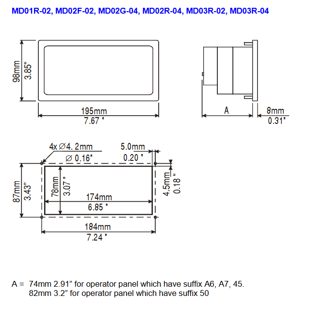
Product installation specifications
Physical dimension requirements: All installation dimensions are in millimeters, with a tolerance of * * ± 0.5mm * *. The cutting dimensions and panel thickness vary for different models/suffixes (45/50/A6/A7), such as the maximum panel thickness of 8mm for ECT-16 and 9mm for ECT-VGA.
Preparation before installation: Remove the red battery protection strip from the panel, prepare the matching fixed bracket and sealing gasket (rectangular/linear, shipped with model).
Installation of sealing gasket
Rectangular sealing gasket: applied around the cutting edge, without tension, replaced after each disassembly and assembly.
Linear sealing gasket (thin+thick strip): The thin strip fits the cut, and the thick strip is attached to the panel frame, starting from the midpoint/1/3 of the lower side, with no overlap at both ends.
Fixing method: Place the four fixing brackets in the long corners of the panel, tighten the fixing screws until the panel frame contacts the installation surface.
Power supply and grounding (core requirements)
Protective earth (PE) must be connected, which can be grounded through the screw/quick terminal next to the power terminal. Power terminal 3 also needs to be grounded.
The power supply needs to have dual/reinforced insulation, and the power supply circuit can be floating or grounded. The floating circuit is connected to the power supply ground through a 1M Ω resistor and a 10nF capacitor.
Ensure that the power supply meets the power consumption requirements of the panel, and all electronic devices of the control system must be grounded in a standardized manner.
Interface connection and module installation
Port wiring: The layout of ports varies among different models. The location of the core ports (POWER/PLC/PC/AUX) can be found in the corresponding model diagram. The PLC port pins are defined as the core (such as 1-pin chassis ground, 2-pin RXD, 3-pin TXD, 5-pin GND, etc.).
AUX module installation steps
Turn off the panel power; 2) Loosen the two screws on the back cover; 3) Remove the back cover (eTOP/ePAD series pry open from the side slot); 4) Insert the communication module into the red interface and lock it; 5) Reinstall the back cover and tighten the screws; 6) Paste module function labels in the designated area.
No PC/Printer Port model: This type of model uses PLC Port as a PLC/PC composite port, and requires CA2/CA114 cable in conjunction with a gender converter for programming.
Programming cable: The core is CA2/CA114, used for connecting the panel to the computer, with corresponding cross pins (such as panel RXD connected to computer TXD).
Daily maintenance and component operation
(1) Battery replacement
Battery function: Maintain real-time hardware clock, event list, and recipe data. When the battery is low, there are three prompts: FAULT/FLT LED flashes, the system menu displays Battery LOW, and the S6 bit value of RDA changes.
Replacement steps: 1) Power off; 2) Loosen the 4 screws of the battery compartment; 3) Remove the battery compartment; 4) Replace the CR2430 battery; 5) Reinstall the battery compartment and tighten the screws; 6) Power on verification status.
Attention: Battery replacement may result in loss of backup data. It is strictly prohibited to mix battery models. Waste batteries should be disposed of according to regulations to avoid explosion risks.
(2) Other component operations
Dismantling of nameplate: Pinch the exposed part of the nameplate and slide it downwards to remove it. When replacing, use a nameplate of the same thickness and do not thicken it.
Memory card operation: Some models use SSFDC memory cards, and anti-static measures should be taken during operation: clean the gold fingers (soft tissue), avoid finger contact, and place them in an anti-static box after disassembly. Do not wipe with synthetic cloth.
Panel cleaning: Use only a soft cloth and neutral soap to wipe, do not use solvents.
Basic usage and key commands
Operation mode: The core is divided into configuration mode (programming/calibration) and operation mode (normal operation), which can be switched through buttons/touch screen.
Programming requirements
Software: Designer V6 (Windows application, requires separate system installation).
Communication parameters: baud rate 9600 (up to 38400 for PC port models), no parity check, 1 stop bit, software default adaptation.
Connection: Panel cut configuration mode, connect the computer COM1/COM2 port with CA2/CA114 cable.
Button commands: divided into page mode, alarm mode, data entry mode, password mode, etc., with different button functions in different modes; Models without physical buttons (such as ECT-16) use touch screens to implement virtual buttons; Some models do not have CLEAR keys, and functions can be achieved through combination keys. Long pressing the key for 2 seconds can activate special functions (such as ENTER 2s to enter data entry).
Touchscreen model: Comes with default virtual buttons (CLEAR/ENTER), which automatically pop up a numeric keypad when entering data.
Troubleshooting and Calibration
(1) Enter configuration mode
There are button models: Power off → Press and hold any 3 buttons → Power on and hold until the screen displays the configuration mode.
Keyless touchscreen models (ECT-16/ELT-16/RT-16): Power off → Left hand touches the middle left side of the screen → Power on → Right hand touches the middle right side of the screen once per second until configuration mode is displayed.
(2) Touch screen calibration
Standard calibration: Enter configuration mode → touch the CLEAR key on the screen until a small circular mark appears in the upper right corner → long press the mark to the lower left corner → follow the prompts to touch the designated key/ENTER key in sequence until switching back to operation mode.
Emergency calibration: suitable for situations where standard calibration cannot be entered, power off → power on → touch the middle of the screen once per second until entering calibration mode → execute standard calibration steps.
(3) Fault diagnosis of indicator light (core LED)
LED name, color, status, meaning
Fault/FLT red out with no hardware malfunction, battery is normal
Flashing battery low battery
Constant hardware malfunction
RUN green out hardware malfunction
The constantly lit panel is operating normally
COM green flashing communication error (some models)
Always on, communication is normal
ALARM red out with no alarm
Flashing alarm requires confirmation
Constant light alarm activation
Safety and Usage Guidelines
Applicable standards: Following EN 60204-1 (Industrial Control System Safety), EN 61000-6-4 (Emission Interference), EN 61000-6-2 (Anti Interference), the product comes with CE certification.
Operation taboos
It is prohibited to directly control motors, valves, and other actuators without safety protection using panels to avoid danger caused by malfunctions.
It is prohibited to remove the panel back cover when it is powered on. Before operating the live panel, electrostatic discharge treatment must be carried out first.
Do not use tools such as screwdrivers to operate buttons/touch screens to avoid damage.
Environmental taboos: Avoid long-term exposure of panels to direct sunlight (accelerating panel film aging), and prohibit installation in environments that come into contact with corrosive chemicals.

- YOKOGAWA
- Reliance
- ADVANCED
- SEW
- ProSoft
- WATLOW
- Kongsberg
- FANUC
- VSD
- DCS
- PLC
- man-machine
- Covid-19
- Energy and Gender
- Energy Access
- Renewable Integration
- Energy Subsidies
- Energy and Water
- Net zero emission
- Energy Security
- Critical Minerals
- A-B
- petroleum
- Mine scale
- Sewage treatment
- cement
- architecture
- Industrial information
- New energy
- Automobile market
- electricity
- Construction site
- HIMA
- ABB
- Rockwell
- Schneider Modicon
- Siemens
- xYCOM
- Yaskawa
- Woodward
- BOSCH Rexroth
- MOOG
- General Electric
- American NI
- Rolls-Royce
- CTI
- Honeywell
- EMERSON
- MAN
- GE
- TRICONEX
- Control Wave
- ALSTOM
- AMAT
- STUDER
- KONGSBERG
- MOTOROLA
- DANAHER MOTION
- Bentley
- Galil
- EATON
- MOLEX
- Triconex
- DEIF
- B&W
- ZYGO
- Aerotech
- DANFOSS
- KOLLMORGEN
- Beijer
- Endress+Hauser
- schneider
- Foxboro
- KB
- REXROTH
- YAMAHA
- Johnson
- Westinghouse
- WAGO
- TOSHIBA
- TEKTRONIX
- BENDER
- BMCM
- SMC
- HITACHI
- HIRSCHMANN
- XP POWER
- Baldor
- Meggitt
- SHINKAWA
- Other Brands
- UniOP
- KUKA
- IBA
- Beckhoff
- ADLINK
-
Beckhoff CP6500-1012-0060 - Control Cabinet PC Interface Unit
-
Beckhoff FC5202-0000 - 2-Channel DeviceNet Master PCI Interface Card
-
Beckhoff CP6606-0001-0020 - 7-Inch Economy Panel PC Touch
-
Beckhoff CP2921-0010 - Multi-Touch Integrated Control Panel Display
-
Beckhoff CP7802-0001-0010 - 15-Inch Touch Screen Control Panel HMI
-
Beckhoff C6920-0050 - Control Cabinet Industrial PC
-
Beckhoff BK9105 - EtherNet/IP Bus Coupler Network Interface
-
Beckhoff 31 Modules - Bus Terminal Slice I/O Lot Assortment
-
Beckhoff CX2020-0120 - Embedded PC Basic CPU Module 8GB CFast Card
-
Beckhoff CP7001-0000 - HMI Control Panel Touch Screen
-
B&R 7EX484.50-1 - System 2005 Controller Base Module Slots
-
Beckhoff EK1322 - 2-Port EtherCAT P Extension Feed-In Terminal
-
Beckhoff CP6606-0001-0020 - 7-Inch Single-Touch Economy Panel PC
-
Beckhoff CP6607-0001-0000 - Economy Installation Operator Panel PC 5.7-Inch
-
Beckhoff AX5103-0000-0200 - Digital Compact Servo Driver 3 Phase
-
Beckhoff CP7802-0001-0010 - 15-Inch Touch Screen Control Panel
-
Beckhoff AX8620 - Power Supply Module Axis System
-
Beckhoff CX2030-0121 - Embedded PC Controller Module
-
Beckhoff CP6606-0001-0020 - 7-Inch Economy Panel PC Touch Screen
-
Beckhoff CX2030-0121 - Embedded PC CPU Module Windows Standard 7
-
Beckhoff BX3100-0000 - PROFIBUS DP Bus Terminal Controller
-
Beckhoff CX1020-0000 - Controller Set with Power Supply Unit
-
Beckhoff EK1100 - EtherCAT Coupler Terminal Module Set
-
Beckhoff CP7002-1043-0010 - HMI Display Panel with Control Panel Bracket
-
Beckhoff AM8031-0D10-0000 - Synchronous Servo Motor
-
Beckhoff CX5130-0175 - Embedded PC 4GB RAM Controller
-
Beckhoff CX5130-0155 - Embedded PC Automation Controller
-
Beckhoff C6930-0010 - Control Cabinet Industrial PC Core Duo
-
Beckhoff CP3924-0000 - Multi-Touch Control Panel Display
-
Beckhoff AM8023-0F20-0000 - Synchronous Servo Motor
-
B&R KL3362 - Bus Terminal Thermocouple Input Module
-
Beckhoff AL2006-0000-0000 - Linear Servo Motor Three Phase
-
Beckhoff CX5140-0155 - Embedded PC CPU Controller Module
-
Beckhoff FC9002 - Ethernet PCI Network Interface Card
-
Beckhoff CP7203-0021-0040 - Built-In Panel PC 19-Inch Touch Screen
-
Beckhoff C6930-0020 - Control Cabinet Industrial PC HDD CF Card
-
Beckhoff CX2900-0033 - Memory Card CFast Storage
-
Beckhoff CP6201-0001-0020 - Built-In Panel PC Display
-
b+m surface systems C6930-1121-0060 - Industrial PC Beckhoff Core i7
-
Beckhoff CP2221-0010 - Multi-Touch Built-In Panel PC
-
Beckhoff C6017-0010 - Ultra-Compact Industrial PC
-
Beckhoff FC5102-0000 - 2-Channel CANopen PCI Interface Card
-
Beckhoff CP7021-0000-0000 - HMI Control Panel Interface
-
Beckhoff CP2216-0020 - Multi-Touch Built-In Panel PC
-
Beckhoff C6140 - Industrial PC Tower System Pentium 4
-
Beckhoff AM3033-1E40 - Servo Motor with Gearbox Assembly
-
Beckhoff CX9020-0115 - Embedded PC CPU Controller Module
-
Beckhoff CP6809-0001-0000 - Built-In Control Panel HMI Terminal
-
Beckhoff CP3919-0000 - Multi-Touch Control Panel Touchscreen Monitor
-
Beckhoff AM8053-0LHB-0000 - Synchronous Servo Motor
-
Beckhoff C6920-1028-0000 - Control Cabinet Industrial Computer PC
-
Beckhoff CX1100-0014 - Power Supply Unit for CX1030
-
Beckhoff CX9001-0101 - Embedded PC CPU Controller Module
-
Beckhoff CP3916-1428-0000 - Control Panel Multi-Touch Monitor
-
Beckhoff CP7037-1027-0010 - HMI Built-In Control Panel PC
-
Beckhoff CX1020-0120 - CPU Module DVI USB Windows Standard
-
Beckhoff CX5020-0121 - Embedded PC Controller Module
-
Beckhoff EL5042 - 2-Channel Encoder Interface BiSS C EtherCAT Terminal
-
Beckhoff CP7201-0021-0040 - Built-In Panel PC Touch Monitor
-
B&R X20-RT-8401 - reACTION Technology Module I/O Block
-
Beckhoff CP2915-0010 - HMI Control Panel Display Touch Screen
-
Beckhoff EL7221 - Servomotor Cyber Terminal EtherCAT Module
-
Beckhoff CX5140-0175 - Embedded PC CPU Module
-
Beckhoff C6017-0010 - Ultra-Compact Industrial PC
-
Beckhoff CX2020-0130 - Embedded PC Basic CPU Module
-
Beckhoff CX1030-0011 - Basic CPU Module Windows CE 6.0
-
Beckhoff AM8043-1E00-0000 - Synchronous Servo Motor
-
Beckhoff CX1020-0110 - CPU Module Controller Interface Bundle
-
Beckhoff C6930-1069-0030 - Control Cabinet Industrial PC Mainboard CB3054-0001
-
Beckhoff KL9528 - Power Supply Terminal Module
-
Beckhoff AM8053-0K20-0000 - Synchronous Servo Motor
-
Beckhoff CX5020-1111 - Embedded PC Controller Module
-
Beckhoff CX5130-0175 - Embedded PC CPU Module Intel Atom
-
Beckhoff CP6401-1024-0040 - Husky Display Control Panel HMI Terminal
-
Beckhoff CP2616-0000 - Multi-Touch Display Automation Panel PC
-
Beckhoff CP7921-1075-0000 - 12-Inch HMI Control Panel ELO Touch
-
Beckhoff C6930-0060 - Control Cabinet Industrial PC SSD
-
Beckhoff AX5112-0000 - Digital Compact Servo Drive 3 Phase
-
Beckhoff C6930-0040 - Control Cabinet Industrial PC Intel Core i5
-
Beckhoff CP2616-0000 - Multi-Touch Display Automation Panel PC
-
Beckhoff KL1414 - 4-Channel Digital Input Bus Terminal
-
Beckhoff CX1020-0000 - Basic CPU Module Controller
-
Beckhoff CP6201-1008-0000 - 12-Inch Built-In Panel PC
-
Beckhoff CP7021-0000 - HMI Control Panel Display Screen
-
Beckhoff AX5106-0000 - Digital Compact Servo Drive
-
Beckhoff BX3100-0000 - Profibus DP Bus Terminal Controller
-
Beckhoff CP2916-0000 - Multi-Touch Built-In Control Panel
-
Beckhoff C6925-0030 - Fanless Control Cabinet Industrial PC
-
Beckhoff C6330 - Industrial PC Motherboard Boser HS6237 Celeron
-
Beckhoff AM3033-0C00-0000 - Synchronous Servo Motor
-
Beckhoff CP7232-0001-0030 - Control Panel PC HMI
-
Beckhoff CX5020-0122 - Embedded PC CPU Module
-
Beckhoff AM8043-0H10-0000 - Rotary Synchronous Servo Motor
-
Beckhoff CP3924-0010 - Multitouch Control Panel HMI
-
Beckhoff CX9020-0110-1005 - Embedded PC Basic CPU Module
-
Beckhoff BK9105 - EtherNet/IP Bus Coupler
-
Beckhoff CX1500-M310 - Profibus Master Fieldbus Extension Module
-
Beckhoff CX1500-M510 - PROFIBUS Master Fieldbus Extension Module
-
Beckhoff CP9922.0 - TTL-TX Display Transmitter Card
-
Beckhoff CP9010_1 - ISA Slot Interface Card
-
Beckhoff NRL75-DC30S15B - LCD Inverter Board
-
Beckhoff LTD121C30S - Toshiba LCD Display Panel
-
Beckhoff CP7732-1207-0030 - Operating Terminal Panel PC HMI
-
Beckhoff C5102-0010 - Rackmount Industrial Computer PC5000
-
Beckhoff C6015-0010 - Ultra-Compact Industrial PC
-
Beckhoff CB1056-0001 - Industrial PC Motherboard Mainboard
-
Beckhoff AX5103 - Digital Compact Servo Amplifier 1 Axis
-
Beckhoff AM8052-0J00-9000 - Rotary Synchronous Servo Motor
-
Beckhoff CP7932-0002-0000 - Control Panel HMI Display
-
Beckhoff CB1061-0001 - Industrial PC Motherboard Mainboard
-
Beckhoff C5102-0060 - 19-inch Rackmount Industrial PC
-
Beckhoff EL7342 - 2 Channel DC Motor Motion Interface EtherCAT Terminal
-
Beckhoff CX5120-0135 - Embedded PC CPU Module Intel Atom
-
Beckhoff CB1061-G4 - Industrial PC Motherboard Mainboard
-
Beckhoff CX50100121 - Embedded PC CPU Module
-
Beckhoff CX1030-0013-1002 - Basic CPU Module Intel Pentium M
-
Beckhoff CP7802-1075-0010 - Control Panel Touch Screen HMI
-
Beckhoff AM8023-0E20-0000 - Rotary Synchronous Servo Motor
-
Beckhoff EL5032 - 2 Channel Encoder Interface EnDAT EtherCAT Terminal
-
Beckhoff CX5130-0175 - Embedded PC CPU Module Intel Atom
-
Beckhoff CA4040-0000 - PCI Ethernet Network Board
-
Beckhoff C3340 - Panel PC Industrial Workstation
-
Beckhoff EL3068 - 8 Channel Analog Input EtherCAT Terminal 0-10V
-
Beckhoff EL1889 - 16 Channel Digital Input EtherCAT Terminal
-
Beckhoff C6640-0050 - Control Cabinet Industrial PC Intel Core i7
-
Beckhoff PC MIC 3230 TP - Industrial Panel PC Touch Screen
-
Beckhoff CX2040-0135 - Embedded PC Industrial CPU Module
-
Beckhoff CP6202-1020-0010 - Built-in Panel PC HMI

K-JIANG

Add: Jimei North Road, Jimei District, Xiamen, Fujian, China
Tell:+86-15305925923