
K-WANG


Union Special XF500 series sewing machine
Union Special XF500 series sewing machine
Basic Information
Applicable models: covering more than 20 models in the three sub series of XF500 series, classified by needle count:
Single needle models: XF511 series (such as XF511B100MF, XF511H100MG, etc.), suitable for light to medium fabrics;
Double needle models: XF512 series (such as XF512E100HB, XF512E100MP), featuring medium and heavy-duty fabric seams;
Three needle models: XF513 series (such as XF513E100HJ, XF513E100HR), suitable for heavy-duty fabrics (such as denim, workwear).
Core positioning: High speed flat bed double lock sewing machine, designed for factory/industrial sewing scenarios, with industrial grade configurations such as fully enclosed drive mechanism and forced lubrication, balancing sewing efficiency and durability.
Core configuration and key parameters of the product
(1) Core configuration
The role of key characteristics in configuration categories
The drive mechanism is fully enclosed and equipped with a curved needle drive to prevent dust and dirt, extending its service life
The lubrication system is fully automatic with forced lubrication, equipped with replaceable oil filters to continuously lubricate key components and reduce wear
The protective device independently drives the needle guard and safety guard to ensure safe operation and prevent suture entanglement
Heat dissipation design for some models (XF511H series) with built-in oil cooler suitable for high-speed and long-term operation
Special Function Power "AIR-KLIPP" Chain Cutting Machine, Puller Puller for Automatic Wire Cutting, Ensuring Straight Line of Long Seam
(2) Key technical parameters
Parameter Category Core Value Remarks
Sewing speed 6500-9000 R.P.M. XF511H100MF maximum 9000 R.P.M
Needle spacing range 7-14 S.P.I. Single needle models 7-10 S.P.I., some models 10-14 S.P.I
Suitable for needles with 108 GHS, 128 GAS, and 128 GBS sizes of 70/027 (fine) -170/067 (thick)
The working voltage is not clearly indicated, and the lubrication system of the industrial sewing power supply relies on machine power drive
Low inertia presser foot, narrow edge feeding presser foot, etc. are suitable for different fabrics and sewing needs
Lubricating oil Saybolt viscosity 90-125 (100 ° F) Mineral oil meets Union Special specification 175
Installation and lubrication specifications
(1) Installation requirements
The machine needs to be placed on a horizontal workbench, and protective components such as battery protection strips and fixed brackets used during transportation should be removed before installation;
Ensure good ventilation in the work area, reserve sufficient operating space, and install protective covers and safety shields in place;
Check the fastening status of all connecting components (such as needle bars, bent needles, and feeding teeth), and tighten the screws according to the torque requirements in the manual.
(2) Lubrication operation (core maintenance item)
Oil specification: Union Special specification 175 mineral oil with Saybolt viscosity of 90-125 (100 ° F) must be used, and mixing with other types of oil is prohibited;
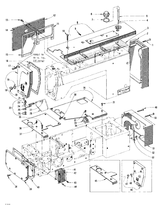
Refueling steps: Remove the refueling cap (A in Figure 1), refuel to the TOP line of the oil level gauge (B in Figure 1), and tighten the refueling cap;
Operation after new machine/long-term shutdown: Run at low speed (300 R.P.M.) for 5 minutes, observe whether the oil flow indicator rises steadily, and confirm that the oil circulation is normal;
Oil change and filter replacement:
Oil change cycle: no more than 1 year, with 2 drain plugs in the oil pan;
Oil filter replacement: It must be replaced every time the oil is changed. Remove the 4 screws (C in Figure 1) and cover plate (D in Figure 1), take out the old oil filter, move the bypass valve from the old oil filter to the new oil filter, and assemble it in reverse.
Key component adjustment process
(1) Needle bar adjustment
Height adjustment: When the curved needle tip is aligned with the left side of the right needle, the top of the pinhole should be 1/64 inch (. 4mm) lower than the lower surface of the curved needle blade;
Alignment adjustment (dual/three needle models): The top of the needle bar is approximately 1 7/8 inches (47.6mm) from the top of the upper needle bar bushing, ensuring that the needle is centered in the needle plate hole. Torque requirements: 10-12 in lbs for early models and 16-18 in lbs for later models;
Taboo: The needle bar has a special coating and must not be pried with tools to avoid damage.
(2) Bending needle adjustment
Single needle model: When the bent needle is at the far right end, the distance from the needle centerline is 5/32 inch (4.0mm), and the maximum gap between the bent needle and the needle during operation is. 002 inch (. 051mm);
Double/Three Needle Models: The distance between the centerline of the right curved needle and the right needle varies depending on the model, and is 1/8 inch (3.2mm) or 5/32 inch (4.0mm), requiring the use of a specialized gauge (such as 21225-5/32);
Synchronous adjustment: Ensure that the distance between the needle and the curved needle is consistent when the machine rotates in both directions, with a deviation of no more than one scale.
(3) Adjustment of fabric delivery system
Feeding tooth height: At the highest position, the tooth tip is 3/64 inches (1.2mm) higher than the needle plate;
Front back/left to right alignment: The feeding teeth should be at the center of the needle plate groove, with even gaps on both sides, which can be fine tuned by adjusting the screws of the needle plate bracket;
Adjustment of fabric feeding height: Loosen the adjusting screw (A in Figure 19), rotate the adjusting disc (B in Figure 19), and turn it towards the operator to increase the fabric feeding height.
(4) Foot pressure and suture tension adjustment
Low inertia presser foot: When the needle bar is at its lowest point, there is a gap of 1/32 inch (. 8mm) between the top of the presser foot screw and the top of the slot. When the presser foot lever is lifted and released, the gap between the connecting rod and the presser bar guide plate is 1/16 inch (1.6mm);
Suture tension:
Needle stitch tension: Adjust to the minimum needle loop that can be pulled up to form a tight needle stitch;
Bending needle and thread tension: Maintain a slight tension to avoid the thread being too tight;
Tension release: When the presser foot is lifted to 1/8 inch (3.2mm), the tension disc begins to release and is fully released when fully lifted.
Special device operation instructions
(1) Power "AIR-KLIPP" chain cutting machine
Adjust parameters:
Cross cutting distance: The distance between the lower blade and the front end of the upper blade is 1/32 inch (. 8mm);
Shear angle: The gap between the lower blade and the upper blade is 0.003 inches (0.076mm);
Pressure regulation: The air motor operates at a pressure of 20-22 p.s.i. (1.5 bar), and the suction pressure is based on the non cutting fabric;
Replace blade: Remove 2 screws from the upper blade, and first remove the upper blade, back cover, and wire inlet from the lower blade. Ensure that the tension spring is inserted into the lower blade hole during installation.
(2) Puller (Belt/Roller type)
Tension adjustment: The deflection of the traction drive belt when pressed is about 1/8 inch (3.2mm), which is adjusted by an eccentric wheel;
Needle spacing combination: With 9 different combinations of sprockets, 59 needle spacings can be achieved, with a default needle spacing of approximately 9.2 S.P.I. for the model;
Timing adjustment: The intermittent feeding of fabric by the tractor needs to be stopped before the needle enters the fabric, by adjusting the position of the sprocket on the shaft.
Preventive Maintenance and Safety Rules
(1) Preventive Maintenance Schedule
table
Core tasks of maintenance cycle
Daily check of oil level (between red lines), pump operation status, cleaning of machine lint, and inspection of protective covers
Replace the oil filter and oil after the first month
Clean the oil cooler and motor air duct monthly
Check the clutch/motor V-belt tension and clutch/brake every 3 months
Change the engine oil and check the internal timing belt tension every 6 months
Annual comprehensive inspection of timing belt wear and component fastening status
(2) Safety operation rules
threading、 Before refueling, adjusting or replacing parts, all power sources must be turned off;
Safety goggles must be worn during operation, and all protective covers and shields must be installed in place. Tampering with safety devices is prohibited;
It is prohibited to directly control actuators without safety protection using machines to avoid danger caused by malfunctions;
When operating with electricity, operators need to first perform electrostatic discharge treatment to prevent static electricity from damaging components.
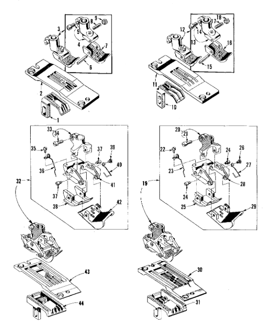
Parts and accessories information
Parts diagram and index: The document includes exploded diagrams of all components such as lubrication system, needle drive, feeding mechanism, presser foot, special device, etc., with part numbers, names, and quantities marked, such as lubrication system parts (C50093 series) and needle assembly (C50055 series);
List of vulnerable parts: needles, suture tension discs, feeding teeth, presser feet, seals (O-rings), oil filters, etc;
Special accessories:
Tools: Needle spacing adjustment wrench (21205B), screwdriver (21207B), tweezers (660-240);
Functional category: Knee control component (29480ADL), single/double/three pin dedicated wire holder (21101W series);
Lubrication: 32 oz (946ml) specialized oil, tubing (C50094 series), oil filter (C50093CA).
- YOKOGAWA
- Reliance
- ADVANCED
- SEW
- ProSoft
- WATLOW
- Kongsberg
- FANUC
- VSD
- DCS
- PLC
- man-machine
- Covid-19
- Energy and Gender
- Energy Access
- Renewable Integration
- Energy Subsidies
- Energy and Water
- Net zero emission
- Energy Security
- Critical Minerals
- A-B
- petroleum
- Mine scale
- Sewage treatment
- cement
- architecture
- Industrial information
- New energy
- Automobile market
- electricity
- Construction site
- HIMA
- ABB
- Rockwell
- Schneider Modicon
- Siemens
- xYCOM
- Yaskawa
- Woodward
- BOSCH Rexroth
- MOOG
- General Electric
- American NI
- Rolls-Royce
- CTI
- Honeywell
- EMERSON
- MAN
- GE
- TRICONEX
- Control Wave
- ALSTOM
- AMAT
- STUDER
- KONGSBERG
- MOTOROLA
- DANAHER MOTION
- Bentley
- Galil
- EATON
- MOLEX
- Triconex
- DEIF
- B&W
- ZYGO
- Aerotech
- DANFOSS
- KOLLMORGEN
- Beijer
- Endress+Hauser
- schneider
- Foxboro
- KB
- REXROTH
- YAMAHA
- Johnson
- Westinghouse
- WAGO
- TOSHIBA
- TEKTRONIX
- BENDER
- BMCM
- SMC
- HITACHI
- HIRSCHMANN
- XP POWER
- Baldor
- Meggitt
- SHINKAWA
- Other Brands
- UniOP
- KUKA
- IBA
- Beckhoff
- ADLINK
-
Beckhoff CP6500-1012-0060 - Control Cabinet PC Interface Unit
-
Beckhoff FC5202-0000 - 2-Channel DeviceNet Master PCI Interface Card
-
Beckhoff CP6606-0001-0020 - 7-Inch Economy Panel PC Touch
-
Beckhoff CP2921-0010 - Multi-Touch Integrated Control Panel Display
-
Beckhoff CP7802-0001-0010 - 15-Inch Touch Screen Control Panel HMI
-
Beckhoff C6920-0050 - Control Cabinet Industrial PC
-
Beckhoff BK9105 - EtherNet/IP Bus Coupler Network Interface
-
Beckhoff 31 Modules - Bus Terminal Slice I/O Lot Assortment
-
Beckhoff CX2020-0120 - Embedded PC Basic CPU Module 8GB CFast Card
-
Beckhoff CP7001-0000 - HMI Control Panel Touch Screen
-
B&R 7EX484.50-1 - System 2005 Controller Base Module Slots
-
Beckhoff EK1322 - 2-Port EtherCAT P Extension Feed-In Terminal
-
Beckhoff CP6606-0001-0020 - 7-Inch Single-Touch Economy Panel PC
-
Beckhoff CP6607-0001-0000 - Economy Installation Operator Panel PC 5.7-Inch
-
Beckhoff AX5103-0000-0200 - Digital Compact Servo Driver 3 Phase
-
Beckhoff CP7802-0001-0010 - 15-Inch Touch Screen Control Panel
-
Beckhoff AX8620 - Power Supply Module Axis System
-
Beckhoff CX2030-0121 - Embedded PC Controller Module
-
Beckhoff CP6606-0001-0020 - 7-Inch Economy Panel PC Touch Screen
-
Beckhoff CX2030-0121 - Embedded PC CPU Module Windows Standard 7
-
Beckhoff BX3100-0000 - PROFIBUS DP Bus Terminal Controller
-
Beckhoff CX1020-0000 - Controller Set with Power Supply Unit
-
Beckhoff EK1100 - EtherCAT Coupler Terminal Module Set
-
Beckhoff CP7002-1043-0010 - HMI Display Panel with Control Panel Bracket
-
Beckhoff AM8031-0D10-0000 - Synchronous Servo Motor
-
Beckhoff CX5130-0175 - Embedded PC 4GB RAM Controller
-
Beckhoff CX5130-0155 - Embedded PC Automation Controller
-
Beckhoff C6930-0010 - Control Cabinet Industrial PC Core Duo
-
Beckhoff CP3924-0000 - Multi-Touch Control Panel Display
-
Beckhoff AM8023-0F20-0000 - Synchronous Servo Motor
-
B&R KL3362 - Bus Terminal Thermocouple Input Module
-
Beckhoff AL2006-0000-0000 - Linear Servo Motor Three Phase
-
Beckhoff CX5140-0155 - Embedded PC CPU Controller Module
-
Beckhoff FC9002 - Ethernet PCI Network Interface Card
-
Beckhoff CP7203-0021-0040 - Built-In Panel PC 19-Inch Touch Screen
-
Beckhoff C6930-0020 - Control Cabinet Industrial PC HDD CF Card
-
Beckhoff CX2900-0033 - Memory Card CFast Storage
-
Beckhoff CP6201-0001-0020 - Built-In Panel PC Display
-
b+m surface systems C6930-1121-0060 - Industrial PC Beckhoff Core i7
-
Beckhoff CP2221-0010 - Multi-Touch Built-In Panel PC
-
Beckhoff C6017-0010 - Ultra-Compact Industrial PC
-
Beckhoff FC5102-0000 - 2-Channel CANopen PCI Interface Card
-
Beckhoff CP7021-0000-0000 - HMI Control Panel Interface
-
Beckhoff CP2216-0020 - Multi-Touch Built-In Panel PC
-
Beckhoff C6140 - Industrial PC Tower System Pentium 4
-
Beckhoff AM3033-1E40 - Servo Motor with Gearbox Assembly
-
Beckhoff CX9020-0115 - Embedded PC CPU Controller Module
-
Beckhoff CP6809-0001-0000 - Built-In Control Panel HMI Terminal
-
Beckhoff CP3919-0000 - Multi-Touch Control Panel Touchscreen Monitor
-
Beckhoff AM8053-0LHB-0000 - Synchronous Servo Motor
-
Beckhoff C6920-1028-0000 - Control Cabinet Industrial Computer PC
-
Beckhoff CX1100-0014 - Power Supply Unit for CX1030
-
Beckhoff CX9001-0101 - Embedded PC CPU Controller Module
-
Beckhoff CP3916-1428-0000 - Control Panel Multi-Touch Monitor
-
Beckhoff CP7037-1027-0010 - HMI Built-In Control Panel PC
-
Beckhoff CX1020-0120 - CPU Module DVI USB Windows Standard
-
Beckhoff CX5020-0121 - Embedded PC Controller Module
-
Beckhoff EL5042 - 2-Channel Encoder Interface BiSS C EtherCAT Terminal
-
Beckhoff CP7201-0021-0040 - Built-In Panel PC Touch Monitor
-
B&R X20-RT-8401 - reACTION Technology Module I/O Block
-
Beckhoff CP2915-0010 - HMI Control Panel Display Touch Screen
-
Beckhoff EL7221 - Servomotor Cyber Terminal EtherCAT Module
-
Beckhoff CX5140-0175 - Embedded PC CPU Module
-
Beckhoff C6017-0010 - Ultra-Compact Industrial PC
-
Beckhoff CX2020-0130 - Embedded PC Basic CPU Module
-
Beckhoff CX1030-0011 - Basic CPU Module Windows CE 6.0
-
Beckhoff AM8043-1E00-0000 - Synchronous Servo Motor
-
Beckhoff CX1020-0110 - CPU Module Controller Interface Bundle
-
Beckhoff C6930-1069-0030 - Control Cabinet Industrial PC Mainboard CB3054-0001
-
Beckhoff KL9528 - Power Supply Terminal Module
-
Beckhoff AM8053-0K20-0000 - Synchronous Servo Motor
-
Beckhoff CX5020-1111 - Embedded PC Controller Module
-
Beckhoff CX5130-0175 - Embedded PC CPU Module Intel Atom
-
Beckhoff CP6401-1024-0040 - Husky Display Control Panel HMI Terminal
-
Beckhoff CP2616-0000 - Multi-Touch Display Automation Panel PC
-
Beckhoff CP7921-1075-0000 - 12-Inch HMI Control Panel ELO Touch
-
Beckhoff C6930-0060 - Control Cabinet Industrial PC SSD
-
Beckhoff AX5112-0000 - Digital Compact Servo Drive 3 Phase
-
Beckhoff C6930-0040 - Control Cabinet Industrial PC Intel Core i5
-
Beckhoff CP2616-0000 - Multi-Touch Display Automation Panel PC
-
Beckhoff KL1414 - 4-Channel Digital Input Bus Terminal
-
Beckhoff CX1020-0000 - Basic CPU Module Controller
-
Beckhoff CP6201-1008-0000 - 12-Inch Built-In Panel PC
-
Beckhoff CP7021-0000 - HMI Control Panel Display Screen
-
Beckhoff AX5106-0000 - Digital Compact Servo Drive
-
Beckhoff BX3100-0000 - Profibus DP Bus Terminal Controller
-
Beckhoff CP2916-0000 - Multi-Touch Built-In Control Panel
-
Beckhoff C6925-0030 - Fanless Control Cabinet Industrial PC
-
Beckhoff C6330 - Industrial PC Motherboard Boser HS6237 Celeron
-
Beckhoff AM3033-0C00-0000 - Synchronous Servo Motor
-
Beckhoff CP7232-0001-0030 - Control Panel PC HMI
-
Beckhoff CX5020-0122 - Embedded PC CPU Module
-
Beckhoff AM8043-0H10-0000 - Rotary Synchronous Servo Motor
-
Beckhoff CP3924-0010 - Multitouch Control Panel HMI
-
Beckhoff CX9020-0110-1005 - Embedded PC Basic CPU Module
-
Beckhoff BK9105 - EtherNet/IP Bus Coupler
-
Beckhoff CX1500-M310 - Profibus Master Fieldbus Extension Module
-
Beckhoff CX1500-M510 - PROFIBUS Master Fieldbus Extension Module
-
Beckhoff CP9922.0 - TTL-TX Display Transmitter Card
-
Beckhoff CP9010_1 - ISA Slot Interface Card
-
Beckhoff NRL75-DC30S15B - LCD Inverter Board
-
Beckhoff LTD121C30S - Toshiba LCD Display Panel
-
Beckhoff CP7732-1207-0030 - Operating Terminal Panel PC HMI
-
Beckhoff C5102-0010 - Rackmount Industrial Computer PC5000
-
Beckhoff C6015-0010 - Ultra-Compact Industrial PC
-
Beckhoff CB1056-0001 - Industrial PC Motherboard Mainboard
-
Beckhoff AX5103 - Digital Compact Servo Amplifier 1 Axis
-
Beckhoff AM8052-0J00-9000 - Rotary Synchronous Servo Motor
-
Beckhoff CP7932-0002-0000 - Control Panel HMI Display
-
Beckhoff CB1061-0001 - Industrial PC Motherboard Mainboard
-
Beckhoff C5102-0060 - 19-inch Rackmount Industrial PC
-
Beckhoff EL7342 - 2 Channel DC Motor Motion Interface EtherCAT Terminal
-
Beckhoff CX5120-0135 - Embedded PC CPU Module Intel Atom
-
Beckhoff CB1061-G4 - Industrial PC Motherboard Mainboard
-
Beckhoff CX50100121 - Embedded PC CPU Module
-
Beckhoff CX1030-0013-1002 - Basic CPU Module Intel Pentium M
-
Beckhoff CP7802-1075-0010 - Control Panel Touch Screen HMI
-
Beckhoff AM8023-0E20-0000 - Rotary Synchronous Servo Motor
-
Beckhoff EL5032 - 2 Channel Encoder Interface EnDAT EtherCAT Terminal
-
Beckhoff CX5130-0175 - Embedded PC CPU Module Intel Atom
-
Beckhoff CA4040-0000 - PCI Ethernet Network Board
-
Beckhoff C3340 - Panel PC Industrial Workstation
-
Beckhoff EL3068 - 8 Channel Analog Input EtherCAT Terminal 0-10V
-
Beckhoff EL1889 - 16 Channel Digital Input EtherCAT Terminal
-
Beckhoff C6640-0050 - Control Cabinet Industrial PC Intel Core i7
-
Beckhoff PC MIC 3230 TP - Industrial Panel PC Touch Screen
-
Beckhoff CX2040-0135 - Embedded PC Industrial CPU Module
-
Beckhoff CP6202-1020-0010 - Built-in Panel PC HMI

K-JIANG

Add: Jimei North Road, Jimei District, Xiamen, Fujian, China
Tell:+86-15305925923