
K-WANG


UniOP Universal Operation Panel Installation Guide
UniOP Universal Operation Panel Installation Guide
Core General Technical Specifications
This guide specifies the general technical parameters of the entire series of panels, with some models having exclusive customized specifications. The core general parameters are shown in the table below, and special model differences are marked separately:
Specification Category Key Parameters Special Model Description
Power supply DC 18-30V; 2A T-type users can replace fuses CP10G-04, ePAD03-06/33C, eTOP03-50c, etc. as overcurrent protection devices without fuses
The mainstream backup battery is a 3V 270mA lithium manganese battery (CR2430), which is non rechargeable and has a lifespan of about 1 year. Users can replace the eTOP04C with a 3V 50mA lithium battery (VL2330), which is rechargeable and non user replaceable
Environmental parameters Operating temperature: 0~+50 ℃; Storage temperature: -20~+70 ℃
Humidity: 5~85% RH (without condensation)
Vibration/Shock: Compliant with EN60068-2-6/27 B7 suffix model, operating temperature -20~+60 ℃; ETOP/ePAD series operating temperature 0~+45 ℃
Protection and Durability: The front panel has a protection level of IP65 (installation requirements must be strictly followed)
Button reliability>3 million times
Resistive touch screens with IP65 protection for over 1 million cycles must be equipped with sealing gaskets as required to ensure the size of the cutting edge, otherwise they will fail
Electromagnetic compatibility emission interference: EN55011 Class A
Anti interference: electrostatic 8KV air/4KV contact, surge ± 2KV power supply, etc., in compliance with EN61000 series standards, fully adaptable to industrial electromagnetic environments, resistant to RF, transient, and conducted interference
Core port parameters PLC port: 300-38400 baud rate, supports RS232/422/485/20mA current loop
PC/printer port: 300-38400 baud rate, only RS232 baud rate may vary slightly depending on the model, some basic models only support 9600
Programming related standard programming software Designer version 6 (Windows application)
Communication parameters: 9600 baud rate, no parity check, 1 stop bit. Models with PC/printer ports support 19200/38400 baud rate
Exclusive parameters for core models of each series (excerpt)
The display, memory, power consumption, and size of the core models are key to installation and adaptation. The following is a list of representative model parameters for key series:
Model Series Representative Model Display Type/Size User Memory 24VDC Maximum Power Consumption (mA) Installation Opening (mm) Weight (Kg)
EPAD series ePAD03 4x20 LCD/2.8 "512KB 250 149x109 1
ePAD33C 30x80 TFT/10.4” 32MB 1200 311x276 -
ETOP series eTOP04C TFT/4.3 "2MB 400 149x109 1
eTOP05 TFT/5.7” 32MB 600 187x147 1.4
eTOP50C XGA TFT/15” 64MB 1500 392x307 3.8
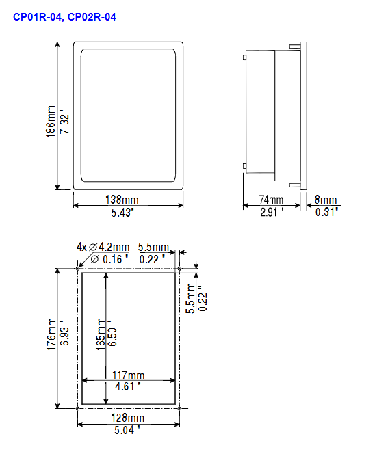
CP series CP01R-04 4x20 LCD 512KB 250 138x186 1.1
CP10G-04 4x20 LCD/2.8” 512KB 300 141x176 1.1
MKDR series MKDR-16 16x40 LCD/5.6 "512KB 500 311x220 2.5
Classic Series BKDC-46 16x40 STN Color Screen/5.6 "32MB 600 275x220 1.9
ETT-VGA 30x80 TFT/9.6” 512KB 700 311x220 2.7
Product installation specifications
Physical size requirements
All installation dimensions are in millimeters, with a uniform tolerance of * * ± 0.5mm * *. The cutting edges, panel thickness, and installation depth of different models/suffixes (45/50/A6/A7) vary, such as eTOP05 opening 187x147mm and eTOP50C opening 392x307mm.
The red battery protection strip must be removed before installation, otherwise it will affect the normal operation of the battery.
Sealing gasket installation (IP65 protective core)
Two types of sealing gaskets, rectangular and linear, are available for panel delivery. They are compatible with the model and must be replaced after disassembly and assembly. The installation requirements are as follows:
Rectangular sealing gasket: applied around the cutting edge of the equipment, tension-free fit, avoiding wrinkles;
Linear sealing gasket: divided into thin and thick strips, with the thin strip fitting the cut (starting from the lower midpoint) and the thick strip sticking to the panel frame (starting from the lower 1/3), with no overlap at both ends.
fixation method
Install 4 fixed brackets on the long edge of the panel near the corner, tighten the fixing screws until the plastic/aluminum frame of the panel is completely in contact with the installation surface to avoid loosening.
Power supply and grounding (mandatory requirement)
The panel must be reliably grounded to protective earth (PE), which can be grounded through screws/quick terminals next to the power terminal. Power terminal 3 also needs to be grounded separately, with a yellow label indicating the grounding position;
The power supply needs to have double/reinforced insulation, and the power supply circuit can be floating or grounded; The floating circuit is connected to the power supply ground through a 1M Ω resistor and a 4.7nF capacitor inside;
It is necessary to ensure that the power supply meets the power consumption requirements of the panel, and all electronic devices in the control system must be grounded in a standardized manner.
Interface configuration and connection
The panel interface is divided into standard core interface, expansion interface, and special function interface. The configuration of different models of interfaces varies greatly. The core interfaces and functions are as follows:
PLC Port: D-15 male, core communication port, used to connect PLC/controller or as UniNET client network port, supports RS232/422/485/20mA current loop, must use corresponding cables, otherwise communication cannot be achieved. Pin 1 is the chassis ground, pin 2 is RXD, and pin 3 is TXD as the core pin.
PC/Printer Port: D-15 female header, only supports RS232, functions vary with panel mode: configuration mode is programming port, UniNET server mode is network port, normal operation mode is serial printer port, programming requires CA2/CA114 cable.
AUX Port: D-9 female head, industrial network expansion port, function determined by optional communication module, pin definition in module manual; Module installation requires power-off operation, and after reinstallation, paste function labels in the designated area.
Ethernet/USB Port: Only equipped with mid to high end eTOP models (eTOP04C/06C/20C/33C/40C/50C), Ethernet is 10/100Mbit, used for device communication, programming, and data transmission; USB has a 1.1 host port and can be connected to a USB flash drive to upgrade firmware/copy data.
Other ports: Some models come with external keyboard ports (connected to ET-F/AT-F keyboards) and DX video ports (eTOP40C/50C); Models without PC/Printer Port use PLC Port as a PLC/PC composite port, and programming requires a gender converter.
Daily maintenance and component operation
(1) Battery replacement
Battery function: Maintaining real-time hardware clock, event list, and recipe data is the core of panel data backup.
Low battery warning: Triple signal - FAULT/FLT LED flashing, system menu displaying Battery LOW, RDA S6 bit value changes, need to be replaced in a timely manner.
Replacement steps: Power off → Loosen the 4 screws of the battery compartment → Remove the battery compartment → Replace with a battery of the same model → Reinstall and tighten → Power on for verification; Replacing will result in the loss of all backup data. Mixing battery models is strictly prohibited, and waste batteries should be disposed of according to regulations to avoid the risk of explosion.
(2) Other maintenance operations
Dismantling of nameplate: Pinch the exposed part of the nameplate and slide it downwards to remove it. When replacing, a nameplate of the same thickness must be used. Thickened nameplates are prohibited to avoid affecting the panel seal.
SSFDC memory card operation: Some models are equipped with strict anti-static measures - clean the gold fingers with soft tissue, prohibit fingers/synthetic cloth from contacting the gold fingers, and place them in an anti-static box after disassembly to avoid contact with oil stains/corrosive substances.
Panel cleaning: Only use a soft cloth and neutral soap to wipe. Do not use any solvents to avoid corroding the panel film and touch screen.
Programming and operational instructions
Programming requirements
Software: Designer version 6, Windows exclusive application, requires separate system installation, supports computer COM1/COM2 ports;
Connection: Switch the panel to configuration mode and connect the computer to the panel using CA2/CA114 cable. The software defaults to communication parameters (9600 baud rate, no parity check, 1 stop bit);
Compatibility: The software version needs to match the panel firmware version, otherwise it cannot be programmed properly.
Operation mode and key commands
Core modes: configuration mode (programming/touch screen calibration), operation mode (normal operation, including sub modes such as data entry, password, alarm, event, etc.);
Key rules: Some models do not have CLEAR keys, which can be achieved through combination keys; Long press the button for 2 seconds to activate special functions (such as ENTER for 2 seconds to enter data entry); Touchscreen models come with CLEAR/ENTER virtual buttons, which automatically pop up a numeric keypad when entering data;
External keyboard support: Some models can be connected to ET-F/AT-F external keyboards, and commands are compatible with the standard keyboard.
Troubleshooting and Touch Screen Calibration
(1) Forced entry into configuration mode
When the panel starts abnormally and cannot switch configuration modes normally, perform the following steps: power off → hold down any 3 buttons → power on and hold the button → until the screen displays configuration mode.
(2) Touch screen calibration
Divided into standard calibration and emergency calibration, emergency calibration is suitable for scenarios where standard calibration cannot be accessed:
Standard calibration: Enter configuration mode → touch the CLEAR button on the screen until a small circular mark appears in the upper right corner → long press the mark to the lower left corner → follow the prompts to touch the designated button/ENTER key in sequence → switch back to operation mode;
Emergency calibration: Power off → Power on → Touch the middle of the screen once per second → Until entering calibration mode → Perform standard calibration steps.
(3) LED fault diagnosis
The panel is equipped with specialized LEDs such as FAULT/DL/RUN/COM/ALARM, which are the core basis for troubleshooting. The status of the core LEDs means:
table
LED name, color, flashing, always on
Fault/FLT red: No hardware failure, battery is normal, battery is low, hardware failure
RUN green hardware failure - panel running normally
COM Green - Communication Error Communication Normal
ALARM red no alarm alarm, alarm activation needs to be confirmed
Safety and Usage Guidelines
Applicable safety standards: Following the EN 60204-1 industrial control system safety standard, it is prohibited to directly control motors, valves, and other actuators without safety protection using panels to avoid personal/equipment hazards caused by malfunctions.
Operation taboos
It is strictly prohibited to remove the panel back cover while powered on to prevent electric shock and equipment damage;
Before operating the live panel, service personnel must perform electrostatic discharge treatment to avoid electrostatic breakdown of components;
Do not use any tools such as screwdrivers or wrenches to operate buttons and touch screens to avoid physical damage.
Environmental taboos
Avoid prolonged exposure of the panel to direct sunlight, which can accelerate the aging of the panel film and affect display and protection;
It is prohibited to install in environments that come into contact with corrosive chemicals. Before installation, the panel film must be tested for its resistance to on-site chemicals.

- YOKOGAWA
- Reliance
- ADVANCED
- SEW
- ProSoft
- WATLOW
- Kongsberg
- FANUC
- VSD
- DCS
- PLC
- man-machine
- Covid-19
- Energy and Gender
- Energy Access
- Renewable Integration
- Energy Subsidies
- Energy and Water
- Net zero emission
- Energy Security
- Critical Minerals
- A-B
- petroleum
- Mine scale
- Sewage treatment
- cement
- architecture
- Industrial information
- New energy
- Automobile market
- electricity
- Construction site
- HIMA
- ABB
- Rockwell
- Schneider Modicon
- Siemens
- xYCOM
- Yaskawa
- Woodward
- BOSCH Rexroth
- MOOG
- General Electric
- American NI
- Rolls-Royce
- CTI
- Honeywell
- EMERSON
- MAN
- GE
- TRICONEX
- Control Wave
- ALSTOM
- AMAT
- STUDER
- KONGSBERG
- MOTOROLA
- DANAHER MOTION
- Bentley
- Galil
- EATON
- MOLEX
- Triconex
- DEIF
- B&W
- ZYGO
- Aerotech
- DANFOSS
- KOLLMORGEN
- Beijer
- Endress+Hauser
- schneider
- Foxboro
- KB
- REXROTH
- YAMAHA
- Johnson
- Westinghouse
- WAGO
- TOSHIBA
- TEKTRONIX
- BENDER
- BMCM
- SMC
- HITACHI
- HIRSCHMANN
- XP POWER
- Baldor
- Meggitt
- SHINKAWA
- Other Brands
- UniOP
- KUKA
- IBA
- Beckhoff
- ADLINK
-
Beckhoff CP6500-1012-0060 - Control Cabinet PC Interface Unit
-
Beckhoff FC5202-0000 - 2-Channel DeviceNet Master PCI Interface Card
-
Beckhoff CP6606-0001-0020 - 7-Inch Economy Panel PC Touch
-
Beckhoff CP2921-0010 - Multi-Touch Integrated Control Panel Display
-
Beckhoff CP7802-0001-0010 - 15-Inch Touch Screen Control Panel HMI
-
Beckhoff C6920-0050 - Control Cabinet Industrial PC
-
Beckhoff BK9105 - EtherNet/IP Bus Coupler Network Interface
-
Beckhoff 31 Modules - Bus Terminal Slice I/O Lot Assortment
-
Beckhoff CX2020-0120 - Embedded PC Basic CPU Module 8GB CFast Card
-
Beckhoff CP7001-0000 - HMI Control Panel Touch Screen
-
B&R 7EX484.50-1 - System 2005 Controller Base Module Slots
-
Beckhoff EK1322 - 2-Port EtherCAT P Extension Feed-In Terminal
-
Beckhoff CP6606-0001-0020 - 7-Inch Single-Touch Economy Panel PC
-
Beckhoff CP6607-0001-0000 - Economy Installation Operator Panel PC 5.7-Inch
-
Beckhoff AX5103-0000-0200 - Digital Compact Servo Driver 3 Phase
-
Beckhoff CP7802-0001-0010 - 15-Inch Touch Screen Control Panel
-
Beckhoff AX8620 - Power Supply Module Axis System
-
Beckhoff CX2030-0121 - Embedded PC Controller Module
-
Beckhoff CP6606-0001-0020 - 7-Inch Economy Panel PC Touch Screen
-
Beckhoff CX2030-0121 - Embedded PC CPU Module Windows Standard 7
-
Beckhoff BX3100-0000 - PROFIBUS DP Bus Terminal Controller
-
Beckhoff CX1020-0000 - Controller Set with Power Supply Unit
-
Beckhoff EK1100 - EtherCAT Coupler Terminal Module Set
-
Beckhoff CP7002-1043-0010 - HMI Display Panel with Control Panel Bracket
-
Beckhoff AM8031-0D10-0000 - Synchronous Servo Motor
-
Beckhoff CX5130-0175 - Embedded PC 4GB RAM Controller
-
Beckhoff CX5130-0155 - Embedded PC Automation Controller
-
Beckhoff C6930-0010 - Control Cabinet Industrial PC Core Duo
-
Beckhoff CP3924-0000 - Multi-Touch Control Panel Display
-
Beckhoff AM8023-0F20-0000 - Synchronous Servo Motor
-
B&R KL3362 - Bus Terminal Thermocouple Input Module
-
Beckhoff AL2006-0000-0000 - Linear Servo Motor Three Phase
-
Beckhoff CX5140-0155 - Embedded PC CPU Controller Module
-
Beckhoff FC9002 - Ethernet PCI Network Interface Card
-
Beckhoff CP7203-0021-0040 - Built-In Panel PC 19-Inch Touch Screen
-
Beckhoff C6930-0020 - Control Cabinet Industrial PC HDD CF Card
-
Beckhoff CX2900-0033 - Memory Card CFast Storage
-
Beckhoff CP6201-0001-0020 - Built-In Panel PC Display
-
b+m surface systems C6930-1121-0060 - Industrial PC Beckhoff Core i7
-
Beckhoff CP2221-0010 - Multi-Touch Built-In Panel PC
-
Beckhoff C6017-0010 - Ultra-Compact Industrial PC
-
Beckhoff FC5102-0000 - 2-Channel CANopen PCI Interface Card
-
Beckhoff CP7021-0000-0000 - HMI Control Panel Interface
-
Beckhoff CP2216-0020 - Multi-Touch Built-In Panel PC
-
Beckhoff C6140 - Industrial PC Tower System Pentium 4
-
Beckhoff AM3033-1E40 - Servo Motor with Gearbox Assembly
-
Beckhoff CX9020-0115 - Embedded PC CPU Controller Module
-
Beckhoff CP6809-0001-0000 - Built-In Control Panel HMI Terminal
-
Beckhoff CP3919-0000 - Multi-Touch Control Panel Touchscreen Monitor
-
Beckhoff AM8053-0LHB-0000 - Synchronous Servo Motor
-
Beckhoff C6920-1028-0000 - Control Cabinet Industrial Computer PC
-
Beckhoff CX1100-0014 - Power Supply Unit for CX1030
-
Beckhoff CX9001-0101 - Embedded PC CPU Controller Module
-
Beckhoff CP3916-1428-0000 - Control Panel Multi-Touch Monitor
-
Beckhoff CP7037-1027-0010 - HMI Built-In Control Panel PC
-
Beckhoff CX1020-0120 - CPU Module DVI USB Windows Standard
-
Beckhoff CX5020-0121 - Embedded PC Controller Module
-
Beckhoff EL5042 - 2-Channel Encoder Interface BiSS C EtherCAT Terminal
-
Beckhoff CP7201-0021-0040 - Built-In Panel PC Touch Monitor
-
B&R X20-RT-8401 - reACTION Technology Module I/O Block
-
Beckhoff CP2915-0010 - HMI Control Panel Display Touch Screen
-
Beckhoff EL7221 - Servomotor Cyber Terminal EtherCAT Module
-
Beckhoff CX5140-0175 - Embedded PC CPU Module
-
Beckhoff C6017-0010 - Ultra-Compact Industrial PC
-
Beckhoff CX2020-0130 - Embedded PC Basic CPU Module
-
Beckhoff CX1030-0011 - Basic CPU Module Windows CE 6.0
-
Beckhoff AM8043-1E00-0000 - Synchronous Servo Motor
-
Beckhoff CX1020-0110 - CPU Module Controller Interface Bundle
-
Beckhoff C6930-1069-0030 - Control Cabinet Industrial PC Mainboard CB3054-0001
-
Beckhoff KL9528 - Power Supply Terminal Module
-
Beckhoff AM8053-0K20-0000 - Synchronous Servo Motor
-
Beckhoff CX5020-1111 - Embedded PC Controller Module
-
Beckhoff CX5130-0175 - Embedded PC CPU Module Intel Atom
-
Beckhoff CP6401-1024-0040 - Husky Display Control Panel HMI Terminal
-
Beckhoff CP2616-0000 - Multi-Touch Display Automation Panel PC
-
Beckhoff CP7921-1075-0000 - 12-Inch HMI Control Panel ELO Touch
-
Beckhoff C6930-0060 - Control Cabinet Industrial PC SSD
-
Beckhoff AX5112-0000 - Digital Compact Servo Drive 3 Phase
-
Beckhoff C6930-0040 - Control Cabinet Industrial PC Intel Core i5
-
Beckhoff CP2616-0000 - Multi-Touch Display Automation Panel PC
-
Beckhoff KL1414 - 4-Channel Digital Input Bus Terminal
-
Beckhoff CX1020-0000 - Basic CPU Module Controller
-
Beckhoff CP6201-1008-0000 - 12-Inch Built-In Panel PC
-
Beckhoff CP7021-0000 - HMI Control Panel Display Screen
-
Beckhoff AX5106-0000 - Digital Compact Servo Drive
-
Beckhoff BX3100-0000 - Profibus DP Bus Terminal Controller
-
Beckhoff CP2916-0000 - Multi-Touch Built-In Control Panel
-
Beckhoff C6925-0030 - Fanless Control Cabinet Industrial PC
-
Beckhoff C6330 - Industrial PC Motherboard Boser HS6237 Celeron
-
Beckhoff AM3033-0C00-0000 - Synchronous Servo Motor
-
Beckhoff CP7232-0001-0030 - Control Panel PC HMI
-
Beckhoff CX5020-0122 - Embedded PC CPU Module
-
Beckhoff AM8043-0H10-0000 - Rotary Synchronous Servo Motor
-
Beckhoff CP3924-0010 - Multitouch Control Panel HMI
-
Beckhoff CX9020-0110-1005 - Embedded PC Basic CPU Module
-
Beckhoff BK9105 - EtherNet/IP Bus Coupler
-
Beckhoff CX1500-M310 - Profibus Master Fieldbus Extension Module
-
Beckhoff CX1500-M510 - PROFIBUS Master Fieldbus Extension Module
-
Beckhoff CP9922.0 - TTL-TX Display Transmitter Card
-
Beckhoff CP9010_1 - ISA Slot Interface Card
-
Beckhoff NRL75-DC30S15B - LCD Inverter Board
-
Beckhoff LTD121C30S - Toshiba LCD Display Panel
-
Beckhoff CP7732-1207-0030 - Operating Terminal Panel PC HMI
-
Beckhoff C5102-0010 - Rackmount Industrial Computer PC5000
-
Beckhoff C6015-0010 - Ultra-Compact Industrial PC
-
Beckhoff CB1056-0001 - Industrial PC Motherboard Mainboard
-
Beckhoff AX5103 - Digital Compact Servo Amplifier 1 Axis
-
Beckhoff AM8052-0J00-9000 - Rotary Synchronous Servo Motor
-
Beckhoff CP7932-0002-0000 - Control Panel HMI Display
-
Beckhoff CB1061-0001 - Industrial PC Motherboard Mainboard
-
Beckhoff C5102-0060 - 19-inch Rackmount Industrial PC
-
Beckhoff EL7342 - 2 Channel DC Motor Motion Interface EtherCAT Terminal
-
Beckhoff CX5120-0135 - Embedded PC CPU Module Intel Atom
-
Beckhoff CB1061-G4 - Industrial PC Motherboard Mainboard
-
Beckhoff CX50100121 - Embedded PC CPU Module
-
Beckhoff CX1030-0013-1002 - Basic CPU Module Intel Pentium M
-
Beckhoff CP7802-1075-0010 - Control Panel Touch Screen HMI
-
Beckhoff AM8023-0E20-0000 - Rotary Synchronous Servo Motor
-
Beckhoff EL5032 - 2 Channel Encoder Interface EnDAT EtherCAT Terminal
-
Beckhoff CX5130-0175 - Embedded PC CPU Module Intel Atom
-
Beckhoff CA4040-0000 - PCI Ethernet Network Board
-
Beckhoff C3340 - Panel PC Industrial Workstation
-
Beckhoff EL3068 - 8 Channel Analog Input EtherCAT Terminal 0-10V
-
Beckhoff EL1889 - 16 Channel Digital Input EtherCAT Terminal
-
Beckhoff C6640-0050 - Control Cabinet Industrial PC Intel Core i7
-
Beckhoff PC MIC 3230 TP - Industrial Panel PC Touch Screen
-
Beckhoff CX2040-0135 - Embedded PC Industrial CPU Module
-
Beckhoff CP6202-1020-0010 - Built-in Panel PC HMI

K-JIANG

Add: Jimei North Road, Jimei District, Xiamen, Fujian, China
Tell:+86-15305925923