
K-WANG


TOSHIBA VF-AS3 inverter RS485 communication function
TOSHIBA VF-AS3 inverter RS485 communication function
Document Overview and Security Standards
Document positioning: Special description of the RS485 communication function of VF-AS3 frequency converter, which needs to be used in conjunction with the main manual (E6582062). The core goal is to achieve remote data exchange between the frequency converter and the controller (PLC/computer) or frequency converter.
Core safety requirements:
Specific safety requirements and risk warnings
Cable operation prohibits live plugging and unplugging of RS485 cables, which may cause equipment failure
Interface restrictions prohibit Ethernet from being connected to RS485 interface for abnormal communication or hardware damage
Storage life: EEPROM write times ≤ 100000 times, RAM unlimited EEPROM overload failure
Communication timeout parameters (F803/F823) must be set for timeout settings. The device cannot stop in case of communication failure
Hardware wiring and transmission specifications
1. RS485 interface definition
VF-AS3 provides 2 RS485 interfaces, and the pin functions are shown in the table below (key pins are bolded):
Interface Type Pin Signal Name Function Description Wiring Requirements
Connector1 (default 2-wire) 4 RXA+/TXA+non-polar transmission and reception data must be connected, shared by 2-wire/4-wire
5 RXB -/TXB - polarity transmission and reception data must be connected, shared by 2/4 wires
8 (3) SG signal ground must be connected to prevent interference
1/2/6- Prohibit connection to avoid short circuit
7 Power prohibits connection to prevent power conflicts
Connector2 (supports 2-wire/4-wire) 4 RXA+/TXA+2-wire transceiver/4-wire receiver [F829]=0 (2-wire) takes effect
5 RXB -/TXB -2-wire transceiver/4-wire receiver [F829] takes effect when=0 (2-wire)
Effective when TXA 4-wire system sends [F829]=1 (4-wire)
Effective when TXB 4-wire system sends [F829]=1 (4-wire)
8 SG signal ground must be connected
2. Wiring specifications
Cable selection: shielded twisted pair, conductor cross-sectional area ≥ AWG24 (0.22mm ²), characteristic impedance 100-120 Ω.
Required resistance:
Terminal resistance: 120 Ω/1/2W, only connected to devices at both ends of the bus.
Up and down resistance: 510 Ω/1/2W, each node needs to be connected to enhance signal stability.
Distance requirement: The distance between communication cables and main circuit cables should be ≥ 20cm to avoid interference; In the 4-wire system, the transmission (TXA/TXB) and reception (RXA/RXB) need to be twisted separately.
3. Transmission specifications
Project Specification Default Values Remarks
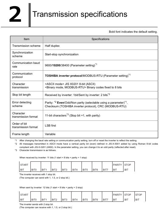
Transmission method half duplex - only receive/send at the same time
Synchronization start and end synchronization - identify the beginning and end of the frame by 3.5 bytes of blank time
Baud rate 9600/19200/38400bps. After changing 19200bps, power off reset is required to take effect
No/even/odd parity check. After the parity check is changed, it needs to be powered off and reset to take effect
Data bit ASCII: 8-bit (JIS X0201); Binary/MODBUS: 8-bit --
Stop bit reception: 1 bit; Send: 2 bits - compatible with devices with 1/1.5/2 stop bits
Error detection Toshiba protocol: checksum; MODBUS:CRC16 - -
Detailed Explanation of Communication Protocol
1. Toshiba inverter protocol (default, [F807]/[F827]=0)
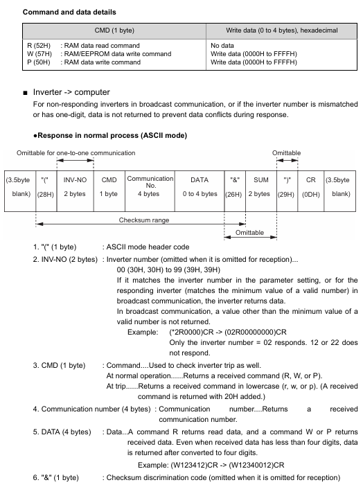
Supports ASCII, Binary, and block communication modes. The core is to access parameters through the "communication number", and commands include R (read), W (write RAM+EEPROM), P (write RAM), S (inter inverter), etc.
ASCII mode:
Format: (INV-NO CMD communication number DATA&SUM) CR (INV-NO: 2 bits, 00-99; SUM optional).
Example: Assuming a frequency of 60Hz (communication number FA01, 60Hz=1770H), the command is (00PFA011770) CR, and the response is (00PFA011770) CR.
Binary mode:
Format: INV-NO CMD communication number DATA SUM (header code "/", INV-NO: 1 bit, 00H-3FH; SUM must be selected.
Example: Read output frequency (communication signal FD00), command is 2F 52 FD 00 82, response is 2F 52 FD 00 17 70 05 (60Hz).
Block communication:
Function: Read and write multiple preset parameters in a single communication ([F870]/[F871] set write parameters, [F875] - [F879] set read parameters).
Format: The computer sends the X command, and the frequency converter sends the Y command back. It supports up to 2 write parameters and 5 read parameters.
2. MODBUS-RTU protocol ([F807]/[F827]=1)
Only partial instructions are supported, with binary data and frame synchronization relying on 3.5 bytes of blank time. The core instructions are shown in the table below:
Example of Applicable Scenarios for Instruction (Hex) Function (Read Output Frequency FD00)
03H reads 1/multiple parameters (indirect reading ≤ 5, direct reading ≤ 8). Computer sends: 01 03 FD 00 00 01 B5 A6; Inverter Return: 01 03 02 17 70 B6 50
06H single write data write 1 parameter write FA01=1770H (60Hz): 01 06 FA 01 17 70 E6 C6
10H block write data write multiple parameters (such as [F870]/[F871]) write FA00+C400 (forward rotation)+ FA01=1770H:01 10 18 70 00 02 04 C4 00 17 70 6D AF
Write and read data simultaneously at 17H+read and write FA00+read FD01/FD00:01 17 18 75 00 02 18 70 00 02 04 C4 00 17 70 XX XX
2BH reads model information, manufacturer/model/version, VFAS3-2037P: 01 2B 0E 01 00 70 77; Return to "TOSHIBA" "VFAS3-2037P" "0100"
CRC calculation: 16 bits, initial value FFFFH, polynomial A001H, with the lower bits first (e.g. the CRC for command 01 03 FD 00 00 01 is B5 A6).
Core function: Communication between frequency converters
Implementing master-slave control of multiple frequency converters through RS485 (without PLC), only supporting Toshiba protocol, core parameters [F806]/[F826] (master-slave mode).
1. Master slave setting
Role parameter setting (F806/F826) function
Main station 3 (sends frequency command)/4 (sends output frequency)/5 (sends torque command)/6 (sends output torque) continuously sends S command (normal)/s command (fault), no response
Receive master station commands from station 0 (0Hz in case of failure)/1 (continue operation in case of failure)/2 (emergency stop in case of failure), but do not respond
2. Speed proportional control
The sub station frequency is proportionally converted by the main station command and supports two-point correction ([F810] - [F814]):
No correction: Slave frequency (Hz)=(Master command (%) x Slave maximum frequency)/10000 (1%=100).
Two point correction: Slave station frequency=[(Point 2 frequency - Point 1 frequency)/(Point 2 command - Point 1 command)] × (Master station command - Point 1 command)+Point 1 frequency.
Example: The master station sends 50% (5000), the maximum frequency of the slave station is 90Hz, and without calibration, the slave station frequency=(5000 × 9000)/10000=45Hz.
Communication related parameters
The core parameters need to be set through the panel or communication, and some require power-off reset to take effect. The key parameters are shown in the table below:
Parameter number, parameter name, function adjustment range, default value, effective method
F800/F820 RS485 baud rate set communication rate 0=9600bps, 1=19200bps, 2=38400bps 1 power-off reset
F801/F821 RS485 verification setting verification method 0=none, 1=even, 2=odd 1 power-off reset
F802 frequency converter number set unique address 0-247 0 immediately
F803/F823 communication timeout setting timeout detection duration 0.0 (disabled), 0.1-100.0s 0.0 immediately
F804/F824 timeout operation timeout action 1=continue running, 4=trip immediately, 6=trip immediately after deceleration, 1=trip immediately
F807/F827 protocol selection: Toshiba/MODBUS 0=Toshiba, 1=MODBUS 0 power off reset
F829 RS485 (2) wiring 2-wire/4-wire switch 0=2 wire, 1=4 wire 0 immediately
Troubleshooting and Appendix
1. Common faults and solutions
Possible causes and solutions for the fault phenomenon
Communication unresponsive 1. Baud rate/checksum/protocol mismatch; 2. Wiring error; 3. Mismatch of frequency converter numbers. 1. Unified parameters (such as 19200bps+even parity+Toshiba protocol); 2. Check the A+/B -/SG wiring and connect the resistor; 3. Confirm that INV-NO is consistent with [F802]
Err5 tripped (communication timeout) 1. Cable disconnected; 2. The timeout period is too short; 3. The main station has no data transmission. 1. Check the cable; 2. Increase [F803]/[F823] (if set to 1.0s); 3. Confirm that the main station is sending commands normally
Write parameter error (N0000): 1. During operation, write prohibited parameters (such as maximum frequency); 2. Parameter locking ([F700]=2/4) 1. Write after shutdown; 2. Set [F700]=0 (unlock)
2. Appendix Information
Appendix 1 (Data Code Table): Provide JIS ASCII codes such as "41H=A" and "30H=0" for ASCII mode data parsing.
Appendix 2 (Response Time): The calculation method is "Data communication time (bytes x bits/baud rate)+frequency converter processing time (maximum 10ms)", for example: 19200bps, 8 bytes, 11 bits, communication time=(8 x 11)/19200 ≈ 4.6ms, total response time ≈ 14.6ms.
Appendix 3 (Model Table): Corresponding to the [FB05] parameter, for example, the FB05 value of VFAS3-2037P (200V/3.7kW) is 9 (decimal).
Key issues
Question 1: What hardware specifications must be followed when wiring RS485 communication for VF-AS3 frequency converter? What are the consequences of ignoring these regulations?
Answer: The hardware specifications that must be followed are as follows:
Cable selection: Use shielded twisted pair cables with a conductor cross-sectional area of ≥ AWG24 (0.22mm ²) and a characteristic impedance of 100-120 Ω. Avoid parallel connection with the main circuit cable (spacing ≥ 20cm) to prevent interference.
Resistance connection:
The devices at both ends of the bus must be connected to a 120 Ω/1/2W terminal resistor (to suppress signal reflection);
All nodes must be connected to 510 Ω/1/2W pull-up and pull-down resistors (to enhance signal driving capability).
Pin and wiring mode:
Connector1 only supports 2-wire system and must be connected to 4-pin (A+), 5-pin (B -), and 8-pin (SG). Connections to pins 1/2/6/7 are prohibited;
Connector2 supports 2-wire/4-wire (F829) switching): The 2-wire system is the same as Connector1, and the 4-wire system requires an additional 3-pin (TXA) and 6-pin (TXB) connection, with separate twisted transmission/reception wires.
Interface restrictions: Ethernet connection to RS485 interface is prohibited, and live plugging and unplugging of communication lines is also prohibited.
The consequences of ignoring norms:
No terminal resistance can cause signal reflection, resulting in communication packet loss or data errors;
No pull-down resistor can cause communication interruption in weak signal environments;
Cables that do not meet the requirements or are parallel to the main circuit can introduce electromagnetic interference, resulting in frequency/current monitoring deviations;
Live plugging or misconnection of Ethernet can damage the RS485 interface circuit and cause equipment failure.
Question 2: How to read the output frequency (communication signal FD00) of VF-AS3 frequency converter through the 03H instruction under the MODBUS-RTU protocol? It is necessary to clarify the instruction format, CRC calculation process, and response parsing.
Answer: Taking "inverter number 1 (01H), baud rate 19200bps, even parity" as an example, the steps are as follows:
1. Instruction format (computer → frequency converter)
The MODBUS-RTU read instruction (03H) is fixed at 8 bytes and follows the following format:
Example value of byte position content description (Hex)
Inverter number 0-247, 0 is broadcast (no response) 01
2 instruction code reading data fixed as 03H 03
The output frequency communication signal of the 3-4 channel signal (high bit → low bit) is FD00H FD 00
5-6 word count (high position → low position) Read 1 parameter fixed as 0001H 00 01
7-8 CRC16 (low bit → high bit) Calculate B5 A6 according to polynomial A001H
Final instruction: 01 03 FD 00 00 01 B5 A6.
2. CRC16 calculation process (taking the first 6 bytes of the instruction "01 03 FD 00 00 01" as an example)
Initial value: FFFFH;
XOR byte by byte:
FFFF XOR 01H = FFFEH;
FFFEH XOR 03H = FFFDH;
FFFDH XOR FD H = FF00H;
FF00H XOR 00H = FF00H;
FF00H XOR 00H = FF00H;
FF00H XOR 01H = FEFFH;
Left shift 8 times per byte, XOR A001H when encountering the lowest bit 1, and the final calculation result is B5A6H (low bit B5H comes first, high bit A6H comes back).
3. Response analysis (frequency converter → computer)
The normal response is 7 bytes, in the following format:
Byte position content description example value (Hex) parsing result
1. The frequency converter number is consistent with the instruction 01-
The instruction code is consistent with the instruction (03H) 03-
3 data bytes 1 parameter=2 bytes 02-
4-5 output frequency (high bit → low bit) unit 0.01Hz 17 70 1770H=6000 → 60.00Hz
CRC B6 50 for 6-7 CRC16 response data-
If the output frequency is 60Hz and the response is 01 03 02 17 70 B6 50, the actual frequency obtained by analysis is 6000 × 0.01=60.00Hz.
Question 3: What are the key requirements for parameter settings between the master and slave stations in VF-AS3 frequency converter communication (master-slave mode)? How to achieve a proportional change in the frequency of the slave station following the master station (for example: the master station sends a 50% command, and the slave station outputs 45Hz)?
Answer:
1. Key parameter settings for master and slave stations (both require Toshiba protocol, [F807]/[F827]=0)
Example of Key Parameter Setting Requirements for Roles (45Hz Output from the Slave Station)
The main station [F806]/[F826] is set to 3 (frequency command)/4 (output frequency), with only one main station [F826]=3 (frequency command)
The master station [F800]/[F820] is consistent with the slave station, with a default of 19200bps 1 (19200bps)
The master station [F801]/[F821] is consistent with the slave station, and defaults to even parity 1 (even parity)
Set station [F806]/[F826] to 0 (fault 0Hz)/1 (fault continues)/2 (fault emergency stop) [F826]=0
Set from station [F823] (timeout) to 0.1-100s (loss of control due to disconnection of defense cable) and 1.0s
Set 21 (Connector1)/22 (Connector2) 22 (using Connector2) from the FMOd (frequency command source)
Set the target maximum frequency from the slave station [FH] (maximum frequency), for example, 90Hz 90.0Hz (9000 × 0.01Hz)
2. Proportional control implementation (without two-point correction, [F810]=0)
Main station instruction calculation: The main station frequency instruction is in units of "%" (1%=100). If a slave station needs to output 45Hz, the main station instruction=(slave station target frequency x 10000)/slave station maximum frequency=(45 x 10000)/90=5000 (i.e. 50%).
Main station sends command: The main station sends S command (53H) through Binary mode, in the format of/INV-NO 53H signal DATA SUM, where:
INV-NO: FFH (broadcast, all received from slave stations);
Communication number: FA05 (Connector2 frequency command);
DATA:5000(50%,Hex=1388H);
Instruction example: 2F FF 53 FA 05 13 88 XX (XX is the SUM value).
Slave frequency conversion: After receiving instructions from the slave station, calculate the frequency according to the formula: Slave frequency (Hz)=(Master station instruction (%) x Slave station maximum frequency)/10000=(5000 × 9000)/10000=4500 → 45.00Hz, achieving proportional following.
- YOKOGAWA
- Reliance
- ADVANCED
- SEW
- ProSoft
- WATLOW
- Kongsberg
- FANUC
- VSD
- DCS
- PLC
- man-machine
- Covid-19
- Energy and Gender
- Energy Access
- Renewable Integration
- Energy Subsidies
- Energy and Water
- Net zero emission
- Energy Security
- Critical Minerals
- A-B
- petroleum
- Mine scale
- Sewage treatment
- cement
- architecture
- Industrial information
- New energy
- Automobile market
- electricity
- Construction site
- HIMA
- ABB
- Rockwell
- Schneider Modicon
- Siemens
- xYCOM
- Yaskawa
- Woodward
- BOSCH Rexroth
- MOOG
- General Electric
- American NI
- Rolls-Royce
- CTI
- Honeywell
- EMERSON
- MAN
- GE
- TRICONEX
- Control Wave
- ALSTOM
- AMAT
- STUDER
- KONGSBERG
- MOTOROLA
- DANAHER MOTION
- Bentley
- Galil
- EATON
- MOLEX
- Triconex
- DEIF
- B&W
- ZYGO
- Aerotech
- DANFOSS
- KOLLMORGEN
- Beijer
- Endress+Hauser
- schneider
- Foxboro
- KB
- REXROTH
- YAMAHA
- Johnson
- Westinghouse
- WAGO
- TOSHIBA
- TEKTRONIX
- BENDER
- BMCM
- SMC
- HITACHI
- HIRSCHMANN
- XP POWER
- Baldor
- Meggitt
- SHINKAWA
- Other Brands
- UniOP
- KUKA
- IBA
- Beckhoff
-
ADLINK CPCI-6860A - 51-31310-OB10 industrial motherboard CompactPCI SBC
-
ADLINK AmITX-SL-G-H110 - 51-7A104-0A30 Mini-ITX Industrial Motherboard
-
ADLINK PXI-2005-003 - CPCI Industrial PC Data Acquisition Card Multi-Function DAQ
-
ADLINK DININ-814M - 51-14032-0A3D SCSI-100P cable connection Interface Terminal Board
-
ADLINK CPCI-3920NA/C2D15/M1G - 3U CompactPCI Intel Core 2 Duo Single Board Computer
-
ADLINK PCIE-8560 - 51-18014-0A20 Communication Card High Speed DAQ
-
ADLINK PCI-C154+ - Motion Control Card 4-axis Motion Controller Board
-
ADLINK PCI-RTV24 - image capture card Analog Video Frame Grabber
-
ADLINK NuPRO-842LV/P - 51-41360-0B30 Industrial Motherboard CPU Board
-
ADLINK cBP-3208/3208R - CPCI Board 3U 8-Slot CompactPCI Backplane
-
ADLINK PCI-8164 - 4-Axis Motion Controller PCI Card 51-12406-0A40
-
ADLINK PCIe-GIE64+ - 4-CH GigE Vision PoE+ Frame Grabber Video Capture Card
-
ADLINK CPCI-6860 / 6860A - CompactPCI Dual Xeon Single Board Computer
-
ADLINK IEC-915GV - REV 1.1 Industrial motherboard CPU Board
-
ADLINK ND-6520 - Technology RS-232 to RS-422RS-485 Converter NuDAM Module
-
ADLINK RTV-24 / PCI-MP4S - 51-12519-1C30 4-Channel Real Time Video Capture Board
-
ADLINK cPCI-6910 / cPCI-6910AM/M1G - cPCI-6910AM/DXL16/M1G/S80G(G)-3120 BOARD CompactPCI SBC
-
ADLINK NUPRO-A40H - Linghua 51-41807-1A30 Industrial Control Computer Motherboard
-
ADLINK USB-3488A - USB to GPIB INTERFACE USB-3488A(G) Controller Module
-
ADLINK PCI-8134A - motion control card 4-Axis Controller Card
-
ADLINK PCI-7432 - Board 32-Channel input / 32-output Isolated Digital I/O PCI Card
-
ADLINK PCI-8134A - 51-12421-0A10 motion controller card tested
-
ADLINK LPCIe-7230 - 32 CH Isolated Input/output Card 2 Interrupts Low Profile PCIe
-
ADLINK NuPRO-E340 - industrial computer motherboard 51-47807-0A30 PICMG 1.3 SHB
-
ADLINK PCI-7434 - High-speed Digital Acquisition Card 64-CH Isolated DO Card
-
ADLINK NuPRO-E330 - 51-41805-0A20 Indsutrial Board SHB Single Board Computer
-
ADLINK PCI-7248 - OPTO-22 48 CHANNEL DIO DIGITAL TTL/DTL I/O 51-12006-0A40 GP
-
ADLINK PCI-8134 - Motion control card 4-Axis Controller Card
-
ADLINK AMP-208C - Movimiento Control Tarjeta 51-12420-1A20 W/Expansión & Breakout
-
ADLINK PCI-8164 - 51-12406-0A40 PCB Board 4-Axis Motion Controller Card
-
ADLINK DIN-68Y-SGII / DIN-68M-J3A - Terminal Board Connector Interface Block
-
ADLINK PCIe-7432 - Technology 51-18402-0A10 PCIe Card With High Input Range
-
ADLINK PCI-8144 / PCI-8144N - Motion control card 4-Axis Stepper Controller Card
-
ADLINK HSL-HUB3/REPEATER - HIGH SPEED LINK EXTENSION MODULES Distributed Hub Module
-
ADLINK ND-6017 - Data Logging + Acquisition 8CH A/D input Mod NuDAM Module
-
ADLINK LPCIe-7250 - data acquisition card Low Profile 8-CH Relay Output Card
-
ADLINK PCI-7432 - I/O card 64-CH Isolated Digital Input Output PCI Card
-
ADLINK IMB-M43H - industrial control computer motherboard Q87 Chip Micro-ATX
-
ADLINK MP-C154 - Motion control Card 4-Axis Motion Controller Board
-
ADLINK PCI-RTV24 - image capture card Video Frame Grabber Card
-
ADLINK PCI-7250 - 8-CH Relay Output & 8-CH Isolated DI Card
-
ADLINK PCI-6308V - 8-CH 12-Bit Isolated Analog Output PCI Card PCB-I-E-1148=6EX2
-
ADLINK PCI-7248 - capture card 48-CH Opto-22 Compatible DIO Card
-
ADLINK HSL-AI16A02-M-VV - Analog Input Output Distributed Module
-
ADLINK NuPRO-A301 - Rev:1.4 NUPRO-A301 PICMG Full-Size Single Board Computer
-
ADLINK PCI-6208V-GL - 8-CH Voltage Analog Output PCI Card
-
ADLINK PCI-8134A - 51-12421-0A10 4-Axis Motion Controller Card
-
ADLINK MNET-S23 - TECHNOLOGY MNET S23 - SERVO DRIVER CONTROL MODULE
-
ADLINK M-342 - ATX I3 I5 I7 Q67 Industrial Motherboard
-
ADLINK NUPRO-780 - Industrial Motherboard CPU Board PICMG SBC
-
ADLINK MP-C154 / MP-C152 - 4-Axis Motion Control Card Pulse-Train Controller
-
ADLINK NuPRO-935A/LV10B0 - Motherboard 51-41802-0A10 GP w/RAM Industrial Control Board
-
ADLINK MP-C154 - Motion control card 4-Axis Motion Controller Mainboard
-
ADLINK PCI-7250 - PCI Acquisition Card 8-CH Relay Output Isolated DI Card
-
ADLINK ACL-7124 - Technology Inc.24 DIO Card Digital Input Output Card
-
ADLINK PCI-8554 A2 - Timer/Counter Data Acquisition Card
-
ADLINK DIN-825-GP4 - Terminal Block Interface Board Breakout Module
-
ADLINK NuPR0-761 - REV:1.1 Industrial motherboard Full-Size PICMG SBC
-
ADLINK MXE-1401/M8G (G) - Matrix Fanless Embedded Computer Industrial PC
-
ADLINK HSL-DI16DO16-UD-NN - Digital 16 Channel I/O Mod Distributed I/O Module
-
ADLINK ND6520 - NUDAM INTELLIGENT DA&C MODULE RS232-RS-422/RS485 CONVERTOR
-
ADLINK NUPRO-761 - REV:1.1 Industrial Motherboard CPU Board
-
ADLINK AMP-208C - Motion Control Card 51-12420-1A20 DSP-based 8-axis
-
ADLINK NuPRO-A301REV 1.4 - with packaging industrial computer motherboard PICMG SBC
-
ADLINK PCM-9112+ - 51-12300-0A2 industrial motherboard Multi-Function DAQ PC/104 Module
-
ADLINK PCM-7250+ - 8-CH Relay Outputs & 8-CH Isolated DI Module PC/104
-
ADLINK PCI-RTV24 - Image capture card Analog Video Frame Grabber
-
ADLINK PCI-8134 - Motion Controller PCI Card 4-Axis Controller Board
-
ADLINK PCI-7432 - Isolated Digital I/O PCI Card
-
ADLINK PCI-8554 A2 - acquisition card Timer/Counter Card
-
ADLINK PCI-8132 - Rev.A2 2-Axis Servo & Stepper Motion Controller Card
-
ADLINK PCI-8132 - Data Acquisition card 2-Axis Motion Controller Card
-
ADLINK EBP-13E4 - 51-46703-0A30 Industrial Backplane Board Passive Backplane
-
ADLINK PCI-800L - Electronic Card Interface Controller Card
-
ADLINK PCIe-GIE72 - 51-18531-0A10 PCB Board GigE Vision Frame Grabber
-
ADLINK DAQ-2010(G)-OOBO - Simultaneous-Sampling Multi-Function DAQ Card
-
ADLINK PCI-9112 - REV.B1 Multifunction DAQ Card Data Acquisition Card
-
ADLINK PCI-7230 - 51-12003-DA60 32-CH Isolated Digital I/O Card
-
ADLINK PCI-7432 - Data Acquisition Card Isolated Digital I/O PCI Card
-
ADLINK ETX-AT-N270-18/LXE - 51-71111-0A20 ETX CPU Module Motherboard
-
ADLINK HSL-DI32-UD-N - DIGITAL INPUT 32 POINTS MODULE Distributed I/O
-
ADLINK AMP-204C - Motion Control card DSP-Based 4-Axis Advanced Controller
-
ADLINK MNET-4XMOG-0050 - Four-axis Motion Controller Distributed Motion Module
-
ADLINK AMP-204C - Motion control card DSP-Based 4-Axis Pulse-Train Controller
-
ADLINK PCI-7442 - Switch card 64-Channel Datalogging & Acquisition Card
-
ADLINK M-302 - Industrial control motherboard ATX PC Board
-
ADLINK NUPRO-852 / NUPRO-852LV - Industrial motherboard Single Board Computer
-
ADLINK PCI-8134 - REV.B1. 4-Axis Motion Controller Card
-
ADLINK PCI-GIE62 + - 51-18502-0A20 2-CH GigE Vision Frame Grabber PoE Card
-
ADLINK PCI-MPG24 - 51-12523-0B20 MPEG4 Card Video Compression Hardware
-
ADLINK HSL-TB32-M-DIN - 32-CH I/O TERMINAL W/ HSL-AI16AO2-M-VV MODULE
-
ADLINK PCI-M114-GL - PCB Ver 2.1 Motion Controller Axis Card
-
ADLINK IMB-M40H - SYM76996H61 motherboard Industrial Computer Mainboard
-
ADLINK NUPRO-A40H - 51-41807-1A20 industrial control motherboard H61 Chip
-
ADLINK PCI-M114-GL - Axis Card Data Acquisition Card PCB VER2.2 Motion Controller
-
ADLINK PCI-8134 - Motion Controller PCI Card 4-Axis Controller Board
-
ADLINK PCI-8102 - Motion control card 2-Axis Servo & Stepper Controller
-
ADLINK NuPRO-841REV:3.0 - motherboard Industrial Control PC Board
-
ADLINK HSL-TB32-U-DIN REV A1 - Breakout Terminal Board Field I/O Module
-
ADLINK AMP-204C - Motion Control card DSP-Based 4-Axis Pulse-Train Controller
-
ADLINK NUPRO-A40H - 51-41807-1A20 industrial control motherboard H61 PC Board
-
ADLINK PCI-6308A / PCI-6308V - 51-12202-0A50 Isolated Analog Output Card
-
ADLINK AMP-204C - DSP-Based 4-Axis Advanced Pulse-Train Motion Controller
-
ADLINK PCI-7434 - Technology 64-Channel Isolated Digital I/O PCI Cards
-
ADLINK CPCI-6840 / CPCI-6840V / PM16/M1G-12G0 - CompactPCI Single Board Computer CPU Module
-
ADLINK PCIE-GIE74 - Motherboard Video Capture Card 51-18531-0A10 Frame Grabber
-
ADLINK NuPRO-E330 - industrial computer equipment motherboard Control Mainboard
-
ADLINK AMP-208C / 51-12420-1A20 - Motion Control Card W/ Expansion & Breakout Board
-
ADLINK HPCI-14S12U - industrial computer baseboard Passive Backplane 14 Slots
-
ADLINK PCI-8164 - 4-Axis Motion Controller PCI Card W/ 1x Cable, 1x Breakout Box
-
ADLINK PCIe-RTV24 - 51-18016-0A20 Image Acquisition Video Capture Card
-
ADLINK M-342 - 5 PCI ATX Motherboard Industrial PC Mainboard
-
ADLINK PCI-FIW64 - 4/2 Channel IEEE1394B Image Capture Card FireWire Frame Grabber
-
ADLINK PCI-7432 - digital IO card 64-CH Isolated Digital Input Output Card
-
ADLINK 51-12001-0C20 - Circuit Board PCI-7200 Data Acquisition Controller Card
-
ADLINK PXI-3920 - PXI 3U cPCI Industrial Controller Embedded System CPU Board
-
ADLINK NuPRO-841REV:2.0 - motherboard Industrial Control PC Board
-
ADLINK NuPro-E330 - 51-41805-0A20 PCB Industrial Control Computer Motherboard
-
ADLINK PCI-RTV24 - Image capture card Analog Video Frame Grabber
-
ADLINK PCI-7442 - Switch card 64-Channel Datalogging & Acquisition Card
-
ADLINK HPX-13S4 - device baseboard Passive Backplane Riser Card
-
ADLINK PCI-9112 REV A.1 - Multi Function DA&C Board Data Acquisition Card
-
ADLINK PCI-7248 - 51-12006-0A40 Card Control 48-CH Digital I/O Module
-
ADLINK CPCI-6860 / 6860A - motherboard CompactPCI Dual Xeon Single Board Computer
-
ADLINK DPAC-3020-11(G) - Embedded PC Automation Controller Machine Control Board
-
ADLINK NuPRO-841 REV:1.0 - industrial control motherboard CPU Board
-
ADLINK MNET-4XMOG-0050 - Four-axis Motion Controller MNET Motion Control Card
-
ADLINK ETX-AT-N270-18/LXE - 51-71111-0A20 ETX CPU Module Motherboard

K-JIANG

Add: Jimei North Road, Jimei District, Xiamen, Fujian, China
Tell:+86-15305925923