
K-WANG


TOSHIBA TOSBERT VF-A3 frequency converter
Equipment specifications:
Voltage level, power range, core application scenarios
200V level 0.4-55kW small and medium-sized motor drive (such as conveyor, fan)
400V level 0.75-75kW medium and large motor drive (such as pumps and compressors)
TOSHIBA TOSBERT VF-A3 frequency converter
Overview and Basic Equipment Information
Positioning: The official user manual for Toshiba TOSBERT VF-A3 series high-performance frequency converters, used to guide users in installation, operation, maintenance, and troubleshooting.
Equipment specifications:
Voltage level, power range, core application scenarios
200V level 0.4-55kW small and medium-sized motor drive (such as conveyor, fan)
400V level 0.75-75kW medium and large motor drive (such as pumps and compressors)
Equipment features:
High reliability: Built in current limiting, retry, soft stop, and instantaneous power-off protection functions to reduce the probability of tripping.
Easy to operate: keyboard style operation panel, supports memory commands, basic settings do not require stopping the machine to consult the manual.
Compact design: The research body integrates multiple protection functions, saving installation space.
Model coding rules: Taking "VFA3-2150P" as an example, the meanings of each part are as follows:
VFA3: Series Code (VF-A3 Series)
2: Voltage level (2=200V level, 4=400V level)
15: Capacity (15kW)
0: Special configuration (0=Standard)
P: Panel configuration (P=equipped with operation panel)
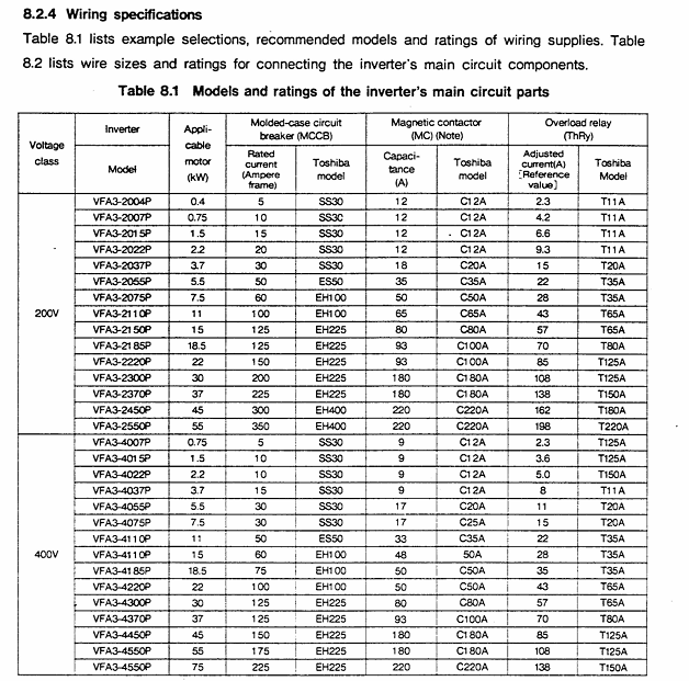
Installation and wiring specifications
1. Installation requirements
Installation method: Only supports vertical wall mounted installation. For non vertical installation, please consult a Toshiba representative.
Ventilation gap (Figure 1.1):
Top/bottom: minimum 10cm
Left and right sides: minimum 5cm
Environmental restrictions:
Temperature: -10 ℃~40 ℃ (up to 50 ℃ without casing)
Humidity: ≤ 90%, no condensation
Altitude: ≤ 1000m (3300ft)
Vibration: Acceleration ≤ 0.5G (20-50Hz), amplitude ≤ 0.1mm (50-100Hz)
Special note: Models with 3.7kW and below have a built-in regenerative discharge resistor on the back. Frequent start stop cycles can cause the exhaust temperature to reach 150 ℃. It is recommended to install it on a metal surface for heat dissipation.
2. Wiring process and specifications
Preparation before wiring:
Disconnect the main switch of the distribution panel and confirm that the "CHARGE" light of the frequency converter is off (to avoid electric shock).
Open the front cover: Pull forward and lift up (Figure 1.2).
Main circuit wiring (Figure 1.3):
Terminal Name Connection Object Precautions
L1/R, L2/S, L3/T 3-phase power input cannot be reversed to the motor end (T1/U, etc.), otherwise the equipment will be damaged
T1/U, T2/V, T3/W 3-phase motors require corresponding motor U, V, and W terminals
The grounding wire of the G/E system complies with Class 3 grounding specifications
R1/T1 (200V level), R38/R41 (400V level) control circuit power supply single-phase signal, ensuring independent power supply for the control circuit
Control circuit wiring:
Frequency setting signal: PP (10Vdc reference) RR(0-10Vdc/0-5Vdc)、IV(0-5Vdc/4-20mAdc), The type needs to be switched through JP1/JP2 jumper (Table 6.1).
Operation control signals: ST (preparation for operation), F (forward rotation), R (reverse rotation), JOG (jog), short circuit the corresponding terminal to CC to achieve the function.
Taboo:
Do not connect power factor compensation capacitors on the power side or motor end.
The control circuit (excluding FLA/FLB/FLC) needs to be insulated from the main circuit to avoid interference.

Operation process and core function settings
1. Operation panel and basic operations
Panel layout (Figure 2.1): including "PANEL CON" LED, MON (monitoring/setting switch), RUN/STOP (run/stop), frequency ± key, parameter setting key (WRT/READ/NEXT, etc.).
Simplify the operation process (trial run, recommended low-frequency startup):
Power ON: When the MCCB is closed, the monitor flashes "OFF" first and then displays "0.0".
Switch panel control: Press the "CTRL" key, and the "PANEL Control" LED will light up.
Set frequency:
Numerical keys: If set to 10Hz, press "1", "0", and "WRT" to display "10" and "FC" alternately.
± key: Long press "△" (increase)/"▽" (decrease), if set to 5.5Hz, press "WRT" to save.
Start/Stop: Press "RUN" to accelerate to the set frequency; Press' STOP 'to slow down and stop.
2. Core Function Settings
(1) Frequency and voltage characteristic settings
Maximum frequency (FH): 30-400Hz (1Hz step size), default 50Hz for 50Hz models and 60Hz for 60Hz models, cannot be modified during operation (requires shutdown).
Torque boost (ub): 0-30% (1% step size), default 3%, used to boost starting torque, excessive can cause overcurrent during startup.
Automatic torque boost (Rub): 0=off, 1=on, automatically adjusts voltage based on load current (Figure 3.4).
Fundamental frequency (uL): 25-400Hz (1Hz step size), set 50Hz for 50Hz motors and 60Hz for 60Hz motors (Table 3.1).
V/f mode (Pt.): 0=constant torque (conveyor), 1=variable torque (fan/pump, energy-saving) (Figure 3.6).
(2) Acceleration, deceleration, and braking control
Acceleration and deceleration time (ACC/DEC):
Range: 0.1-6000 seconds, supports 2 sets of time (ACC1/ACC2, DEC1/DEC2).
Mode: 0=linear, 1=non-linear 1 (slow acceleration at low torque), 2=non-linear 2 (slow acceleration at high speed) (Figure 3.8).
DC injection braking (dbF/dbu/dbt):
Starting frequency (dbF): 0-10Hz, braking voltage (dbu): 0-20%, braking time (dbt): 0-5 seconds, used for precise positioning (Figure 3.27).
Regenerative braking (Pb):
Applicable scenarios for Pb setting function
0 normal load without regenerative braking (or using regenerative discharge unit)
1. There is regenerative braking, no resistance overload detection, and moderate inertia load
2. There is regenerative braking and resistance overload detection for large inertia loads (such as centrifuges)
(3) Multi speed and special operation
Multi speed operation (S1-S7): 7 speeds are achieved through the combination of SS1/SS2/SS3 terminals, with a frequency range from the lower limit frequency (LL) to the upper limit frequency (UL), and can be controlled by panel or external signals (Table 3.7).
Jog operation (JOG): frequency 0-20Hz (0.1Hz step size), only starts when stopped, press the "RUN" button to run, release to stop (Figure 3.21).
Frequency jump (FJ1-FJ3): 3 jump points, set the jump frequency and width to avoid load resonance (Figure 3.24).
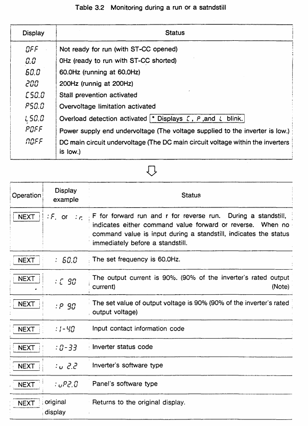
3. Status monitoring and fault reset
Operation/shutdown monitoring: Press the "NEXT" button to cycle through the status (Table 3.2), such as "60.0"=operating frequency 60Hz, "PSO. 0"=overvoltage limit activation, "OC"=overcurrent detection.
Fault monitoring: When tripping, press "NEXT" to check the fault status (such as frequency, current, voltage), and support tracing the last 4 faults (Table 3.4).
Fault reset:
Panel reset: Press "CLR"+"WRT".
External reset: Short circuit the RST-CC terminal (Figure 4.9).
Troubleshooting and Maintenance
1. Fault codes and solutions (Table 9.1)
Meaning of fault code and solution measures
OC1 acceleration overcurrent 1. Increase ACC time; 2. Reduce UB settings; 3. Check if there is a sudden change in the load
OH frequency converter overheating 1. Check the cooling fan; 2. Confirm that the ambient temperature is ≤ 40 ℃; 3. Clean the heat dissipation channel
EF load terminal grounding fault 1. Check the insulation of the motor and output circuit; 2. Check the grounding short circuit point
EEP EEPROM abnormality 1. Restart the power supply; 2. If ineffective, repair/replace EEPROM
2. Regular maintenance and storage
Regular inspection (every 3-6 months):
Terminal screws: Tighten loose screws to prevent poor contact.
Line inspection: Check if the wire crimping point is overheated (discolored) and if the insulation is damaged.
Dust removal: Use a vacuum cleaner to clean the ventilation openings and printed circuit board dust to avoid overheating.
Insulation test: Use a 500V megohmmeter to test the insulation of the main circuit. The motor needs to be tested after disconnecting the frequency converter.
Storage requirements:
Environment: Dry, dust-free, non corrosive gas, temperature -10-40 ℃.
Activation: Long term storage (>2 years) requires power on every 2 years; After removing the storage, the motor needs to be powered on for at least 5 hours before running.
Optional accessories and warranty terms
1. Optional accessories (Table 7.1/7.2)
Type Accessory Name Model Example Function
External installation of input reactor PFL2012-2100 improves power factor and suppresses harmonics
External installation of regenerative discharge resistor PBR3-2055 enhances braking effect, suitable for large inertia loads
Built in multi option printed circuit board VF3X-0888B supports RS-232C communication, BCD code input, etc
External installation of PANEL-KIT (1M/3M/5M) remote control panel, including 1/3/5 meter cable
2. Warranty terms
Warranty period: 12 months after delivery.
Warranty expiration situation:
Unauthorized maintenance/modification of equipment.
Damage caused by vibration/impact during transportation/installation.
Force majeure events such as fires, floods, lightning strikes, and abnormal power grid voltage.
Used for designated purposes of non industrial frequency converters.
Acceptance requirements: After opening the box, check that the equipment is undamaged and the model is consistent with the order. If there are any problems, immediately contact a Toshiba representative.
Key issues
Question 1: What are the space and environmental restrictions that must be followed when installing the TOSBERT VF-A3 frequency converter? What are the consequences of ignoring these restrictions?
Answer:
Restrictions that must be followed:
Installation method: Only supports vertical wall mounting, non vertical installation requires prior consultation with Toshiba representatives.
Ventilation gap: minimum 10cm at the top/bottom, and minimum 5cm on both sides to ensure smooth heat dissipation.
Environmental parameters: temperature -10 ℃~40 ℃ (≤ 50 ℃ without casing), humidity ≤ 90% (no condensation), altitude ≤ 1000m, vibration acceleration ≤ 0.5G (20-50Hz)/amplitude ≤ 0.1mm (50-100Hz).
Special models: Models with 3.7kW and below have regenerative discharge resistors on the back, and the exhaust temperature can reach 150 ℃. It is recommended to avoid installing on flammable surfaces and choose metal surfaces for heat dissipation.
The consequences of ignoring restrictions:
Insufficient ventilation can cause the frequency converter to overheat (fault code OH), triggering a protective shutdown and potentially damaging the power module in the long run.
Excessive humidity/condensation can cause a short circuit and ground fault (EF code) in the main circuit.
Excessive vibration may cause loose terminals, poor contact leading to overcurrent (OC code) or equipment shutdown.
Question 2: In the daily operation of VF-A3 frequency converter, how to set the "DC injection braking" function through the panel to achieve precise motor stop? It is necessary to clarify the setting range and default values of key parameters.
Answer: The steps and key parameters for setting "DC injection braking" through the panel are as follows:
Enter the second functional mode:
Press the "MON" button, and the display will show "no.0 →: t: JP"; Press the "2ND" key to switch to the "2nd" mode.
Select DC injection braking related parameters (function number 0, Table 3.1):
Parameter Name Function Setting Range Default Value Operation Instructions
When the DBF (DC injection braking start frequency) motor drops to this frequency, it triggers the braking 0-10Hz (0.1Hz step size) 0Hz. Press "READ" to read the current value, press "△/▽" or the numerical key to adjust, and press "WRT" to save
DBU (DC injection braking voltage) injects a DC voltage that accounts for 0-20% (1% step size) during braking. If the voltage is too high, it will cause the motor to overheat. It is recommended to adjust according to the inertia of the load (such as 10% -15%)
DBT (DC injection braking time) braking duration 0-5 seconds (0.1 second step) 0 seconds. It is necessary to ensure that the time is sufficient to stop the motor and avoid incomplete braking caused by too short a time
Confirm settings: Press the "MON" key to return to the original display (frequency/OFF), and the settings will take effect.
Attention: DC injection braking is only activated during deceleration and stopping process, and should be accompanied by appropriate deceleration time (DEC) to avoid triggering overcurrent protection due to excessive current during braking.
Question 3: What are the possible reasons when the VF-A3 frequency converter displays "OC1" (acceleration overcurrent) fault? What are the corresponding solutions? What safety precautions should be taken during troubleshooting?
Answer:
Reason for "OC1" fault: During acceleration, the main circuit current exceeds the protection threshold. Common reasons include:
The acceleration time (ACC) is set too short, and the motor speed cannot keep up with the frequency increase, resulting in excessive stalling current.
The torque boost (ub) is set too high, causing overcurrent due to high voltage during startup.
Sudden load changes in the motor (such as sudden blockage of the conveyor), and the load current exceeds the rated output of the frequency converter.
Poor wiring of the main circuit (such as loose wiring at the motor end) can cause current fluctuations.
Solution:
Extend acceleration time: Enter the first function ("MON" → select function number 2), adjust "ACC1/ACC2" to a longer time (such as changing from 1 second to 3 seconds), and press "WRT" to save.
Reduce torque boost: Enter the first function (function number 1), reduce the "ub" value (such as from 10% to 5%), and avoid starting overvoltage.
Check the load: Check if the mechanical load is stuck, clean up foreign objects or reduce the load to ensure that the load is within the rated range of the motor.
Check wiring: Disconnect the power supply (MCCB), confirm that the "CHARGE" light is off, tighten the terminal screws of the main circuit (L1/R, T1/U, etc.), and check the insulation of the circuit.
Check safety precautions:
Before checking all wiring, the main switch of the distribution panel must be disconnected and wait for the "CHARGE" light to turn off (to avoid electric shock caused by residual voltage of the capacitor).
When adjusting parameters, it is necessary to ensure that the frequency converter is in a stopped state. Modifying acceleration time/torque increase during operation may cause equipment instability.
If the fault still exists after multiple troubleshooting, it is necessary to check the motor insulation (using a 500V megohmmeter) to avoid overcurrent caused by internal short circuit of the motor.
- YOKOGAWA
- Reliance
- ADVANCED
- SEW
- ProSoft
- WATLOW
- Kongsberg
- FANUC
- VSD
- DCS
- PLC
- man-machine
- Covid-19
- Energy and Gender
- Energy Access
- Renewable Integration
- Energy Subsidies
- Energy and Water
- Net zero emission
- Energy Security
- Critical Minerals
- A-B
- petroleum
- Mine scale
- Sewage treatment
- cement
- architecture
- Industrial information
- New energy
- Automobile market
- electricity
- Construction site
- HIMA
- ABB
- Rockwell
- Schneider Modicon
- Siemens
- xYCOM
- Yaskawa
- Woodward
- BOSCH Rexroth
- MOOG
- General Electric
- American NI
- Rolls-Royce
- CTI
- Honeywell
- EMERSON
- MAN
- GE
- TRICONEX
- Control Wave
- ALSTOM
- AMAT
- STUDER
- KONGSBERG
- MOTOROLA
- DANAHER MOTION
- Bentley
- Galil
- EATON
- MOLEX
- Triconex
- DEIF
- B&W
- ZYGO
- Aerotech
- DANFOSS
- KOLLMORGEN
- Beijer
- Endress+Hauser
- schneider
- Foxboro
- KB
- REXROTH
- YAMAHA
- Johnson
- Westinghouse
- WAGO
- TOSHIBA
- TEKTRONIX
- BENDER
- BMCM
- SMC
- HITACHI
- HIRSCHMANN
- XP POWER
- Baldor
- Meggitt
- SHINKAWA
- Other Brands
- UniOP
- KUKA
- IBA
- Beckhoff
-
ADLINK CPCI-6860A - 51-31310-OB10 industrial motherboard CompactPCI SBC
-
ADLINK AmITX-SL-G-H110 - 51-7A104-0A30 Mini-ITX Industrial Motherboard
-
ADLINK PXI-2005-003 - CPCI Industrial PC Data Acquisition Card Multi-Function DAQ
-
ADLINK DININ-814M - 51-14032-0A3D SCSI-100P cable connection Interface Terminal Board
-
ADLINK CPCI-3920NA/C2D15/M1G - 3U CompactPCI Intel Core 2 Duo Single Board Computer
-
ADLINK PCIE-8560 - 51-18014-0A20 Communication Card High Speed DAQ
-
ADLINK PCI-C154+ - Motion Control Card 4-axis Motion Controller Board
-
ADLINK PCI-RTV24 - image capture card Analog Video Frame Grabber
-
ADLINK NuPRO-842LV/P - 51-41360-0B30 Industrial Motherboard CPU Board
-
ADLINK cBP-3208/3208R - CPCI Board 3U 8-Slot CompactPCI Backplane
-
ADLINK PCI-8164 - 4-Axis Motion Controller PCI Card 51-12406-0A40
-
ADLINK PCIe-GIE64+ - 4-CH GigE Vision PoE+ Frame Grabber Video Capture Card
-
ADLINK CPCI-6860 / 6860A - CompactPCI Dual Xeon Single Board Computer
-
ADLINK IEC-915GV - REV 1.1 Industrial motherboard CPU Board
-
ADLINK ND-6520 - Technology RS-232 to RS-422RS-485 Converter NuDAM Module
-
ADLINK RTV-24 / PCI-MP4S - 51-12519-1C30 4-Channel Real Time Video Capture Board
-
ADLINK cPCI-6910 / cPCI-6910AM/M1G - cPCI-6910AM/DXL16/M1G/S80G(G)-3120 BOARD CompactPCI SBC
-
ADLINK NUPRO-A40H - Linghua 51-41807-1A30 Industrial Control Computer Motherboard
-
ADLINK USB-3488A - USB to GPIB INTERFACE USB-3488A(G) Controller Module
-
ADLINK PCI-8134A - motion control card 4-Axis Controller Card
-
ADLINK PCI-7432 - Board 32-Channel input / 32-output Isolated Digital I/O PCI Card
-
ADLINK PCI-8134A - 51-12421-0A10 motion controller card tested
-
ADLINK LPCIe-7230 - 32 CH Isolated Input/output Card 2 Interrupts Low Profile PCIe
-
ADLINK NuPRO-E340 - industrial computer motherboard 51-47807-0A30 PICMG 1.3 SHB
-
ADLINK PCI-7434 - High-speed Digital Acquisition Card 64-CH Isolated DO Card
-
ADLINK NuPRO-E330 - 51-41805-0A20 Indsutrial Board SHB Single Board Computer
-
ADLINK PCI-7248 - OPTO-22 48 CHANNEL DIO DIGITAL TTL/DTL I/O 51-12006-0A40 GP
-
ADLINK PCI-8134 - Motion control card 4-Axis Controller Card
-
ADLINK AMP-208C - Movimiento Control Tarjeta 51-12420-1A20 W/Expansión & Breakout
-
ADLINK PCI-8164 - 51-12406-0A40 PCB Board 4-Axis Motion Controller Card
-
ADLINK DIN-68Y-SGII / DIN-68M-J3A - Terminal Board Connector Interface Block
-
ADLINK PCIe-7432 - Technology 51-18402-0A10 PCIe Card With High Input Range
-
ADLINK PCI-8144 / PCI-8144N - Motion control card 4-Axis Stepper Controller Card
-
ADLINK HSL-HUB3/REPEATER - HIGH SPEED LINK EXTENSION MODULES Distributed Hub Module
-
ADLINK ND-6017 - Data Logging + Acquisition 8CH A/D input Mod NuDAM Module
-
ADLINK LPCIe-7250 - data acquisition card Low Profile 8-CH Relay Output Card
-
ADLINK PCI-7432 - I/O card 64-CH Isolated Digital Input Output PCI Card
-
ADLINK IMB-M43H - industrial control computer motherboard Q87 Chip Micro-ATX
-
ADLINK MP-C154 - Motion control Card 4-Axis Motion Controller Board
-
ADLINK PCI-RTV24 - image capture card Video Frame Grabber Card
-
ADLINK PCI-7250 - 8-CH Relay Output & 8-CH Isolated DI Card
-
ADLINK PCI-6308V - 8-CH 12-Bit Isolated Analog Output PCI Card PCB-I-E-1148=6EX2
-
ADLINK PCI-7248 - capture card 48-CH Opto-22 Compatible DIO Card
-
ADLINK HSL-AI16A02-M-VV - Analog Input Output Distributed Module
-
ADLINK NuPRO-A301 - Rev:1.4 NUPRO-A301 PICMG Full-Size Single Board Computer
-
ADLINK PCI-6208V-GL - 8-CH Voltage Analog Output PCI Card
-
ADLINK PCI-8134A - 51-12421-0A10 4-Axis Motion Controller Card
-
ADLINK MNET-S23 - TECHNOLOGY MNET S23 - SERVO DRIVER CONTROL MODULE
-
ADLINK M-342 - ATX I3 I5 I7 Q67 Industrial Motherboard
-
ADLINK NUPRO-780 - Industrial Motherboard CPU Board PICMG SBC
-
ADLINK MP-C154 / MP-C152 - 4-Axis Motion Control Card Pulse-Train Controller
-
ADLINK NuPRO-935A/LV10B0 - Motherboard 51-41802-0A10 GP w/RAM Industrial Control Board
-
ADLINK MP-C154 - Motion control card 4-Axis Motion Controller Mainboard
-
ADLINK PCI-7250 - PCI Acquisition Card 8-CH Relay Output Isolated DI Card
-
ADLINK ACL-7124 - Technology Inc.24 DIO Card Digital Input Output Card
-
ADLINK PCI-8554 A2 - Timer/Counter Data Acquisition Card
-
ADLINK DIN-825-GP4 - Terminal Block Interface Board Breakout Module
-
ADLINK NuPR0-761 - REV:1.1 Industrial motherboard Full-Size PICMG SBC
-
ADLINK MXE-1401/M8G (G) - Matrix Fanless Embedded Computer Industrial PC
-
ADLINK HSL-DI16DO16-UD-NN - Digital 16 Channel I/O Mod Distributed I/O Module
-
ADLINK ND6520 - NUDAM INTELLIGENT DA&C MODULE RS232-RS-422/RS485 CONVERTOR
-
ADLINK NUPRO-761 - REV:1.1 Industrial Motherboard CPU Board
-
ADLINK AMP-208C - Motion Control Card 51-12420-1A20 DSP-based 8-axis
-
ADLINK NuPRO-A301REV 1.4 - with packaging industrial computer motherboard PICMG SBC
-
ADLINK PCM-9112+ - 51-12300-0A2 industrial motherboard Multi-Function DAQ PC/104 Module
-
ADLINK PCM-7250+ - 8-CH Relay Outputs & 8-CH Isolated DI Module PC/104
-
ADLINK PCI-RTV24 - Image capture card Analog Video Frame Grabber
-
ADLINK PCI-8134 - Motion Controller PCI Card 4-Axis Controller Board
-
ADLINK PCI-7432 - Isolated Digital I/O PCI Card
-
ADLINK PCI-8554 A2 - acquisition card Timer/Counter Card
-
ADLINK PCI-8132 - Rev.A2 2-Axis Servo & Stepper Motion Controller Card
-
ADLINK PCI-8132 - Data Acquisition card 2-Axis Motion Controller Card
-
ADLINK EBP-13E4 - 51-46703-0A30 Industrial Backplane Board Passive Backplane
-
ADLINK PCI-800L - Electronic Card Interface Controller Card
-
ADLINK PCIe-GIE72 - 51-18531-0A10 PCB Board GigE Vision Frame Grabber
-
ADLINK DAQ-2010(G)-OOBO - Simultaneous-Sampling Multi-Function DAQ Card
-
ADLINK PCI-9112 - REV.B1 Multifunction DAQ Card Data Acquisition Card
-
ADLINK PCI-7230 - 51-12003-DA60 32-CH Isolated Digital I/O Card
-
ADLINK PCI-7432 - Data Acquisition Card Isolated Digital I/O PCI Card
-
ADLINK ETX-AT-N270-18/LXE - 51-71111-0A20 ETX CPU Module Motherboard
-
ADLINK HSL-DI32-UD-N - DIGITAL INPUT 32 POINTS MODULE Distributed I/O
-
ADLINK AMP-204C - Motion Control card DSP-Based 4-Axis Advanced Controller
-
ADLINK MNET-4XMOG-0050 - Four-axis Motion Controller Distributed Motion Module
-
ADLINK AMP-204C - Motion control card DSP-Based 4-Axis Pulse-Train Controller
-
ADLINK PCI-7442 - Switch card 64-Channel Datalogging & Acquisition Card
-
ADLINK M-302 - Industrial control motherboard ATX PC Board
-
ADLINK NUPRO-852 / NUPRO-852LV - Industrial motherboard Single Board Computer
-
ADLINK PCI-8134 - REV.B1. 4-Axis Motion Controller Card
-
ADLINK PCI-GIE62 + - 51-18502-0A20 2-CH GigE Vision Frame Grabber PoE Card
-
ADLINK PCI-MPG24 - 51-12523-0B20 MPEG4 Card Video Compression Hardware
-
ADLINK HSL-TB32-M-DIN - 32-CH I/O TERMINAL W/ HSL-AI16AO2-M-VV MODULE
-
ADLINK PCI-M114-GL - PCB Ver 2.1 Motion Controller Axis Card
-
ADLINK IMB-M40H - SYM76996H61 motherboard Industrial Computer Mainboard
-
ADLINK NUPRO-A40H - 51-41807-1A20 industrial control motherboard H61 Chip
-
ADLINK PCI-M114-GL - Axis Card Data Acquisition Card PCB VER2.2 Motion Controller
-
ADLINK PCI-8134 - Motion Controller PCI Card 4-Axis Controller Board
-
ADLINK PCI-8102 - Motion control card 2-Axis Servo & Stepper Controller
-
ADLINK NuPRO-841REV:3.0 - motherboard Industrial Control PC Board
-
ADLINK HSL-TB32-U-DIN REV A1 - Breakout Terminal Board Field I/O Module
-
ADLINK AMP-204C - Motion Control card DSP-Based 4-Axis Pulse-Train Controller
-
ADLINK NUPRO-A40H - 51-41807-1A20 industrial control motherboard H61 PC Board
-
ADLINK PCI-6308A / PCI-6308V - 51-12202-0A50 Isolated Analog Output Card
-
ADLINK AMP-204C - DSP-Based 4-Axis Advanced Pulse-Train Motion Controller
-
ADLINK PCI-7434 - Technology 64-Channel Isolated Digital I/O PCI Cards
-
ADLINK CPCI-6840 / CPCI-6840V / PM16/M1G-12G0 - CompactPCI Single Board Computer CPU Module
-
ADLINK PCIE-GIE74 - Motherboard Video Capture Card 51-18531-0A10 Frame Grabber
-
ADLINK NuPRO-E330 - industrial computer equipment motherboard Control Mainboard
-
ADLINK AMP-208C / 51-12420-1A20 - Motion Control Card W/ Expansion & Breakout Board
-
ADLINK HPCI-14S12U - industrial computer baseboard Passive Backplane 14 Slots
-
ADLINK PCI-8164 - 4-Axis Motion Controller PCI Card W/ 1x Cable, 1x Breakout Box
-
ADLINK PCIe-RTV24 - 51-18016-0A20 Image Acquisition Video Capture Card
-
ADLINK M-342 - 5 PCI ATX Motherboard Industrial PC Mainboard
-
ADLINK PCI-FIW64 - 4/2 Channel IEEE1394B Image Capture Card FireWire Frame Grabber
-
ADLINK PCI-7432 - digital IO card 64-CH Isolated Digital Input Output Card
-
ADLINK 51-12001-0C20 - Circuit Board PCI-7200 Data Acquisition Controller Card
-
ADLINK PXI-3920 - PXI 3U cPCI Industrial Controller Embedded System CPU Board
-
ADLINK NuPRO-841REV:2.0 - motherboard Industrial Control PC Board
-
ADLINK NuPro-E330 - 51-41805-0A20 PCB Industrial Control Computer Motherboard
-
ADLINK PCI-RTV24 - Image capture card Analog Video Frame Grabber
-
ADLINK PCI-7442 - Switch card 64-Channel Datalogging & Acquisition Card
-
ADLINK HPX-13S4 - device baseboard Passive Backplane Riser Card
-
ADLINK PCI-9112 REV A.1 - Multi Function DA&C Board Data Acquisition Card
-
ADLINK PCI-7248 - 51-12006-0A40 Card Control 48-CH Digital I/O Module
-
ADLINK CPCI-6860 / 6860A - motherboard CompactPCI Dual Xeon Single Board Computer
-
ADLINK DPAC-3020-11(G) - Embedded PC Automation Controller Machine Control Board
-
ADLINK NuPRO-841 REV:1.0 - industrial control motherboard CPU Board
-
ADLINK MNET-4XMOG-0050 - Four-axis Motion Controller MNET Motion Control Card
-
ADLINK ETX-AT-N270-18/LXE - 51-71111-0A20 ETX CPU Module Motherboard

K-JIANG

Add: Jimei North Road, Jimei District, Xiamen, Fujian, China
Tell:+86-15305925923