
K-WANG


GE VMIVME-2540 24 channel intelligent counter/controller
Frequency measurement: The measurement range covers 0.0076Hz to 2.5MHz. In 16 bit counter mode, the maximum accuracy in the 0.007-76Hz frequency band is 0.015%. The error calculation formula for the 76Hz-2.5MHz frequency band is "100 × (frequency/5MHz)"; Supports 16 bit enhanced resolution mode (requires 2 16 bit counters), with a measurement range extended to 0.001Hz-1.25MHz, and has a 16 bit pre division function of ÷ 2-65536 (maximum clock rate of 2.5MHz).
GE VMIVME-2540 24 channel intelligent counter/controller
Core functions and features
(1) Multi dimensional measurement function
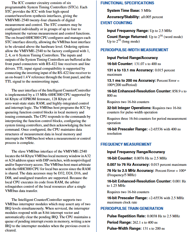
Event counting: Supports input frequencies up to 2.5MHz, with a counting range of up to 232 (approximately 4 billion events) in long mode and 216 in word mode, allowing for accurate counting of external event occurrences.
Frequency measurement: The measurement range covers 0.0076Hz to 2.5MHz. In 16 bit counter mode, the maximum accuracy in the 0.007-76Hz frequency band is 0.015%. The error calculation formula for the 76Hz-2.5MHz frequency band is "100 × (frequency/5MHz)"; Supports 16 bit enhanced resolution mode (requires 2 16 bit counters), with a measurement range extended to 0.001Hz-1.25MHz, and has a 16 bit pre division function of ÷ 2-65536 (maximum clock rate of 2.5MHz).
Cycle/pulse width measurement: In 16 bit counter mode, the cycle measurement range is 400ns-131.07s, with a maximum accuracy of 0.015% for 131s-13.1ms. The error calculation formula for 13.1s-200ns is "100 × (200ns/cycle)"; 16 bit enhanced resolution mode (requires 2 16 bit counters) with a periodic measurement range of 800ns-858.9s; In 32-bit integer operations, pulse width measurement requires 2 16 bit counters, cycle measurement requires 3 16 bit counters, and supports discrete or continuous measurement modes with low data transmission delay.
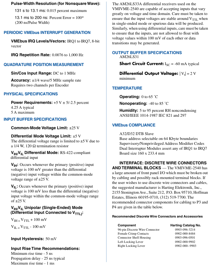
Orthogonal position measurement: Supports sin/cos signal input (frequency 0-1MHz), uses a 32-bit counter, has limit/modulus check function, measurement accuracy of ± 1/4 wave (5MHz sampling rate), requires 2 channels corresponding to 1 encoder, can accurately obtain rotational or linear position information.
(2) Flexible generation function
Square wave/pulse sequence generation: pulse repetition frequency of 0.0038Hz-2.5MHz, period range of 400ns-262.1s, pulse width range of 200ns-131s; In terms of non square wave pulse width accuracy, the maximum error calculation formula for the 131s-13.1ms frequency band is 0.015%, and the error calculation formula for the 13.1ms-200ns frequency band is "100 × (200ns/pulse width)", which supports N pulse sequence outputs with programmable duty cycles.
Timer/Periodic VMEbus Interrupt: Interrupt repetition frequency of 0.0076-1000Hz, capable of asserting any 2 interrupt levels in IRQ1-IRQ7, providing an 8-bit interrupt vector, automatically clearing pending requests after interrupt triggering, facilitating system timing control and event response.
Orthogonal position control output: Control resolution up to ± 1/4 wave, maximum step rate of 1.25MHz, maximum single instruction step count of ± 32767, can drive the actuator to achieve precise position adjustment.
(3) Hardware and interface advantages
Core processor and storage: Equipped with a 15MHz 68HC000 CPU, 64KB EPROM (firmware storage) and 128KB zero wait static RAM (for data buffering and command queues), it can autonomously complete measurement and control tasks, reducing the burden on the host CPU.
VMEbus compatibility: Complies with ANSI/IEEE 1014-1987 and IEC 821-297 standards, supports A32/A24 address space, D32/D16/D8 (EO) data access, and provides a 64KB VMEbus memory window; Support privileged/non privileged address modifiers, shared RAM requires host and onboard CPU to arbitrate access, and supports non aligned data transfer.
Signal interface: Adopting RS-422 differential interface, compatible with single ended TTL input (achieved by connecting the RS-422 inverting input terminal to a 1.4V reference); Provide 24 clock channels, 24 gate control channels, and 24 discrete outputs, with a total of 24 control/measurement interfaces. The front-end panel is connected to the signal through high-density connectors (such as 96 pin discrete wiring connectors). Differential signals are recommended to use 24AWG twisted pair cables (maximum transmission distance of 4000 feet), and TTL signals are recommended to use 30AWG ribbon cables (maximum transmission distance of 50 feet).
Self checking and data exchange: Supports continuous measurement mode, allowing for repeated data collection without the need for host intervention; The data exchange complies with the ANSI/IEEE 754-1985 32-bit floating-point arithmetic standard, and the integer mode supports signed and unsigned operations with complement codes. The onboard state monitoring circuit can provide feedback on the hardware operating status.
Key technical parameters
Parameter category specific specifications
System time base 5MHz, accuracy/stability ± 0.005%
Power requirement+5V DC (allowing ± 5%/-2.5% fluctuation), typical current 4.25A, maximum current 5A
Input buffer common mode voltage limit ± 25V, differential mode voltage limit ± 5V (due to 120 Ω/1/4W terminal resistance); RS-422 differential mode
V IH (positive terminal is 100mV higher than negative terminal), V IL (positive terminal is 100mV lower than negative terminal); Single ended mode V IH=V TTL+100mV, V IL=V TTL − 100mV; Input hysteresis of 50mV, minimum rise time of 5ns, typical propagation delay of 25ns, maximum rise time of 1ms
The output buffer adopts AM26LS31 driver, with a typical short-circuit current of -60mA and a minimum differential mode output voltage of 2V
Environmental parameters: working temperature 0-65 ℃, storage temperature -40-85 ℃, relative humidity 5% -95% (non condensing)
Physical size 6U Eurocard version, dimensions 160mm (depth) x 233.4mm (height), compatible with standard VMEbus chassis
The mean time between failures (MTBF) is not clearly labeled with specific values and meets industrial reliability standards
Ordering options and matching accessories
(1) Order Code Rules
The order model format is "VMIVME-2540-A C-D E F", and the core configuration options are as follows:
A (number of interfaces): 0=4 channels, 1=8 channels, in addition to supporting 16 channels and 24 channels (by configuring 1-6 system timing controllers STC, each STC provides 4 interfaces).
C/D/E/F: The specific functions are not clearly marked in the document, and it is speculated that they are reserved options (such as signal isolation, wide temperature design, etc.), which need to be confirmed with the manufacturer.
(2) Recommended accessories
Accessory name, model/specification
96 pin discrete wiring connectors Harting 0903-096-3214 (connector body), 0902-000-8484 (female crimping terminal), 0903-096-0501 (housing), 0902-000-9902 (left locking rod), 0902-000-9903 (right locking rod)
TTL signal ribbon cable connector ERNI 913.031 (96 pin female connector, compatible with 30AWG ribbon cable)
Signal transfer panel VMIAC-BT04 (19 inch rack mounted, transferring 2 96 pin DIN connector signals to standard terminal blocks, recommended with 3-foot long 96 core ribbon cable connection board)
Application scenarios
This intelligent counter/controller is suitable for multi domain scenarios that require high-precision digital measurement and control, mainly including:
Industrial automation: Rotating axis instrumentation (angular position, velocity, acceleration measurement), linear position measurement (distance, velocity, acceleration), compatible with machine tools, elevators, bridge cranes, X-Y workbenches, and automatic warehouse retrieval systems.
Automotive testing: brake system, gearbox performance testing, tachometer signal acquisition and simulation.
Special equipment and scientific research: robot motion control, telescope/observatory positioning system, medical/laboratory instruments (such as precision fluid control, sample stage drive).
- YOKOGAWA
- Reliance
- ADVANCED
- SEW
- ProSoft
- WATLOW
- Kongsberg
- FANUC
- VSD
- DCS
- PLC
- man-machine
- Covid-19
- Energy and Gender
- Energy Access
- Renewable Integration
- Energy Subsidies
- Energy and Water
- Net zero emission
- Energy Security
- Critical Minerals
- A-B
- petroleum
- Mine scale
- Sewage treatment
- cement
- architecture
- Industrial information
- New energy
- Automobile market
- electricity
- Construction site
- HIMA
- ABB
- Rockwell
- Schneider Modicon
- Siemens
- xYCOM
- Yaskawa
- Woodward
- BOSCH Rexroth
- MOOG
- General Electric
- American NI
- Rolls-Royce
- CTI
- Honeywell
- EMERSON
- MAN
- GE
- TRICONEX
- Control Wave
- ALSTOM
- AMAT
- STUDER
- KONGSBERG
- MOTOROLA
- DANAHER MOTION
- Bentley
- Galil
- EATON
- MOLEX
- Triconex
- DEIF
- B&W
- ZYGO
- Aerotech
- DANFOSS
- KOLLMORGEN
- Beijer
- Endress+Hauser
- schneider
- Foxboro
- KB
- REXROTH
- YAMAHA
- Johnson
- Westinghouse
- WAGO
- TOSHIBA
- TEKTRONIX
- BENDER
- BMCM
- SMC
- HITACHI
- HIRSCHMANN
- XP POWER
- Baldor
- Meggitt
- SHINKAWA
- Other Brands
- UniOP
- KUKA
- IBA
- Beckhoff
- ADLINK
-
Beckhoff EP9224-0037 - 4-Channel Power Distribution Box EtherCAT
-
Beckhoff CX2900-0026 - Solid State Flash Memory Card 20GB CFast
-
Beckhoff BK7500 - SERCOS Interface Fieldbus Bus Coupler Terminal
-
Beckhoff Ep2328-0002 - 4-Channel Input 4-Channel Output EtherCAT Box IP67
-
Beckhoff CX1020-0111 - Controller Kit Combo Interface Modules
-
B&R X20AI2237 - X20 System Analog Input Interface Module
-
Beckhoff CP2221-0010 - Multi-Touch Built-In Panel PC Touchscreen
-
Beckhoff CX1500-M310 - Fieldbus Master Interface Module 24V
-
Beckhoff CX2100-0904 - Power Charging Module Smart UPS Extension
-
Beckhoff CP3918-0000 - Multi-Touch Control Panel 18.5-Inch Monitor
-
Beckhoff CP2915-0000 - 15-Inch Multi-Touch Built-In Control Panel
-
Beckhoff CP7037-1027 - HMI Industrial Control Panel Built-In PC
-
Beckhoff EL3152 - 2-Channel Analog Input Terminal 4-20mA EtherCAT
-
Beckhoff CP6607-0000-0020 - 5.7-Inch Built-In Panel PC HMI Touch
-
Beckhoff EJ1809-0000 - 16-Channel Digital Input Pluggable Signal Level Terminal
-
Beckhoff AM8563-0N10-0000 - Synchronous Servo Motor
-
Beckhoff AX2006-S60600-520 - Compact Servo Drive Inverter
-
Beckhoff AM8053-0K20-0000 - Servo Motor with Planetary Gearbox AG3210
-
Beckhoff AM8042-0FH1-0000 - Synchronous Servo Motor
-
Rexroth R911338600 - IndraControl V HMI Terminal Beckhoff PCI Card FC9002
-
Beckhoff AX5125-0000 - 3 Phase Industrial Servo Drive 1000Hz
-
Beckhoff EP2328-0002 - 4-Channel Digital Input 4-Channel Output EtherCAT Box
-
B&R 7CP476-02 - System 2005 RTD CPU Module 3IF681.86 Interface
-
Beckhoff AX8620-0000-0000 - Power Supply Module Axis Drive System
-
Beckhoff CX1010-0111 - PLC Module CPU Controller 24V
-
Beckhoff AM8043-0H10-0000 - Synchronous Servo Motor
-
Beckhoff C6240-1009 - Control Cabinet Industrial PC Mainframe
-
Beckhoff BX8000-0000 - Bus Terminal Controller HW 4.4 Standalone
-
Beckhoff CP7721-1089-0020 - 12.1-Inch Touch Screen HMI Panel PC
-
Beckhoff CP7132-0001 - Industrial Built-In Panel PC Screen
-
Beckhoff CP2912-0010 - Multi-Touch Built-In Control Panel Display
-
Beckhoff CP2915-0000 - 15-Inch Multi-Touch Built-In Control Panel
-
Beckhoff AM8532-1EN0-0000 - Synchronous Servo Motor
-
Beckhoff AX5203-0000 - 2-Channel Digital Compact Servo Drive
-
Beckhoff CX2020-0141 - Embedded PC Core CPU Module
-
Beckhoff CP6832-0002-0010 - Built-In Industrial Control Panel Display
-
Beckhoff CX5020-0112 - Embedded PC CPU Control Module
-
Beckhoff CX5140-0175 - 4GB Embedded PC CPU Unit 24V
-
Beckhoff EL3681-0030 - Digital Multimeter Calibration Terminal EtherCAT
-
Beckhoff CP7201-1000-0000 - Industrial PC Touch Screen HMI Monitor
-
Beckhoff CP7232-1001-0000 - Industrial Panel PC Touch Screen
-
Beckhoff C6930-1032-0040 - Control Cabinet Industrial PC System
-
Beckhoff AX5125-0000 - 3 Phase Industrial Servo Drive 1000Hz
-
Beckhoff CP3916-1424-0000 - Multi-Touch Built-In Control Panel
-
B&R 1900071142 - Lemoine Fieldbus Communication Interface Module
-
Beckhoff EL2872 - 16-Channel Ribbon Cable Digital Output Terminal
-
Beckhoff CX2030-0120 - Embedded PC CPU Base Module Controller
-
Beckhoff CP3919-0000 - 19-Inch Multi-Touch Control Panel Touchscreen
-
Beckhoff AX5101-0000-0202 - Servo Driver Compact Intelligent Drive 180V
-
Beckhoff CX5130-0135 - Embedded PC Controller Module
-
Beckhoff CP3719-1061-0010 - Multi-Touch Panel PC Outer Housing Enclosure
-
Beckhoff CP3919-1033-0000 - 19-Inch Touch Industrial Panel Keyboard
-
Beckhoff CX5020-0111 - Embedded PC PLC CPU Module
-
Beckhoff FC5102-0000 - 2-Channel CANopen PCI Control Board Card
-
Beckhoff CX9001-1101 - Embedded PC CPU Network I/O System Module
-
Beckhoff CX1100-0920 - Smart Position Sensor Interface Module
-
B&R 4P3040.01-490 - Operator Panel PLC Interface Communication Module
-
Beckhoff CP2612-0000 - Dual-Touch Built-In Panel PC HMI
-
Beckhoff CP7002-1043-0010 - Touchscreen Display HMI Panel Terminal
-
Beckhoff CX9020-0115 - Embedded PC Controller Module
-
Beckhoff CX5140-0155 - 4GB Embedded PC CPU Module Die Industry
-
B&R 7DI435.7 - System 2005 Universal Digital Input Output Module
-
Bihl+Wiedemann BWU1568 - AS-i Master to Profibus Gateway Module
-
Beckhoff C6920-0070 - Control Cabinet Industrial PC 8GB Win 10
-
B&R X20AI2322 - 2-Channel Temperature Analog Input Module
-
Beckhoff CP2912-0000 - 12-Inch Touchscreen Display Monitor Screen
-
Beckhoff CP6022-1001-0010 - 15-Inch Built-In Control Panel
-
Beckhoff AM8031-0D10-0000 - Synchronous Servo Motor
-
Beckhoff CX5010-0111 - Embedded PC Controller CPU Module
-
Beckhoff CP7232-1000-0000 - Industrial Panel PC Touch Display Screen
-
Beckhoff CP7802-0011-0000 - 15-Inch Industrial Touchscreen Control Panel
-
Beckhoff C6320 - Control Cabinet Industrial PC
-
Beckhoff CX1030-0012 - Basic CPU Module Windows CE 6.0
-
Beckhoff CP2919-0000 - Installation Multi-Touch Control Panel
-
Beckhoff CX1020-0000 - Controller Set Stack System Pack
-
B&R 3DO480.6 - System 2005 Digital Output Module
-
Beckhoff EL3101 - 1-Channel Analog Input Terminal Differential +/-10V
-
Beckhoff AX8108-0200-0000 - Axis Feed Module Servo Drive
-
Beckhoff CP7802-1241-0010 - 15-Inch Industrial Touchscreen Control Panel
-
Beckhoff FC2002-0000 - 2-Channel Lightbus Data Acquisition PCI Card
-
Beckhoff CX5120-0155 - 2GB Embedded PC Intel Atom Controller
-
Beckhoff Cx9020-0111 - 1GB Basic CPU Module Embedded PC
-
Beckhoff CP6901-0001-0000 - 12-Inch Economy Built-In Control Panel
-
Beckhoff CX9020-0111 - Embedded PC CPU Basic Module
-
Beckhoff CX5130-0100 - 4GB Embedded PC CPU Module
-
Beckhoff CP2715-0010 - Multi-Touch Built-In Panel PC
-
Beckhoff CX2033-0175 - Embedded PC CPU Module Core i7
-
Beckhoff CP7201-1000-0000 - 12-Inch Touchscreen Panel PC AMAT Green Box
-
Beckhoff EL4038 - 8-Channel Analog Output Terminal 0-10V EtherCAT
-
Beckhoff CP6802-0000-0000 - Built-In Control Panel HMI Screen
-
Beckhoff CP6500-1012-0060 - Control Cabinet PC Interface Unit
-
Beckhoff FC5202-0000 - 2-Channel DeviceNet Master PCI Interface Card
-
Beckhoff CP6606-0001-0020 - 7-Inch Economy Panel PC Touch
-
Beckhoff CP2921-0010 - Multi-Touch Integrated Control Panel Display
-
Beckhoff CP7802-0001-0010 - 15-Inch Touch Screen Control Panel HMI
-
Beckhoff C6920-0050 - Control Cabinet Industrial PC
-
Beckhoff BK9105 - EtherNet/IP Bus Coupler Network Interface
-
Beckhoff 31 Modules - Bus Terminal Slice I/O Lot Assortment
-
Beckhoff CX2020-0120 - Embedded PC Basic CPU Module 8GB CFast Card
-
Beckhoff CP7001-0000 - HMI Control Panel Touch Screen
-
B&R 7EX484.50-1 - System 2005 Controller Base Module Slots
-
Beckhoff EK1322 - 2-Port EtherCAT P Extension Feed-In Terminal
-
Beckhoff CP6606-0001-0020 - 7-Inch Single-Touch Economy Panel PC
-
Beckhoff CP6607-0001-0000 - Economy Installation Operator Panel PC 5.7-Inch
-
Beckhoff AX5103-0000-0200 - Digital Compact Servo Driver 3 Phase
-
Beckhoff CP7802-0001-0010 - 15-Inch Touch Screen Control Panel
-
Beckhoff AX8620 - Power Supply Module Axis System
-
Beckhoff CX2030-0121 - Embedded PC Controller Module
-
Beckhoff CP6606-0001-0020 - 7-Inch Economy Panel PC Touch Screen
-
Beckhoff CX2030-0121 - Embedded PC CPU Module Windows Standard 7
-
Beckhoff BX3100-0000 - PROFIBUS DP Bus Terminal Controller
-
Beckhoff CX1020-0000 - Controller Set with Power Supply Unit
-
Beckhoff EK1100 - EtherCAT Coupler Terminal Module Set
-
Beckhoff CP7002-1043-0010 - HMI Display Panel with Control Panel Bracket
-
Beckhoff AM8031-0D10-0000 - Synchronous Servo Motor
-
Beckhoff CX5130-0175 - Embedded PC 4GB RAM Controller
-
Beckhoff CX5130-0155 - Embedded PC Automation Controller
-
Beckhoff C6930-0010 - Control Cabinet Industrial PC Core Duo
-
Beckhoff CP3924-0000 - Multi-Touch Control Panel Display
-
Beckhoff AM8023-0F20-0000 - Synchronous Servo Motor
-
B&R KL3362 - Bus Terminal Thermocouple Input Module
-
Beckhoff AL2006-0000-0000 - Linear Servo Motor Three Phase
-
Beckhoff CX5140-0155 - Embedded PC CPU Controller Module
-
Beckhoff FC9002 - Ethernet PCI Network Interface Card
-
Beckhoff CP7203-0021-0040 - Built-In Panel PC 19-Inch Touch Screen
-
Beckhoff C6930-0020 - Control Cabinet Industrial PC HDD CF Card
-
Beckhoff CX2900-0033 - Memory Card CFast Storage
-
Beckhoff CP6201-0001-0020 - Built-In Panel PC Display

K-JIANG

Add: Jimei North Road, Jimei District, Xiamen, Fujian, China
Tell:+86-15305925923