
K-WANG


GE VMIVME-3122 High Performance 16 Bit Analog to Digital Converter (ADC)
GE VMIVME-3122 High Performance 16 Bit Analog to Digital Converter (ADC)
Product Overview
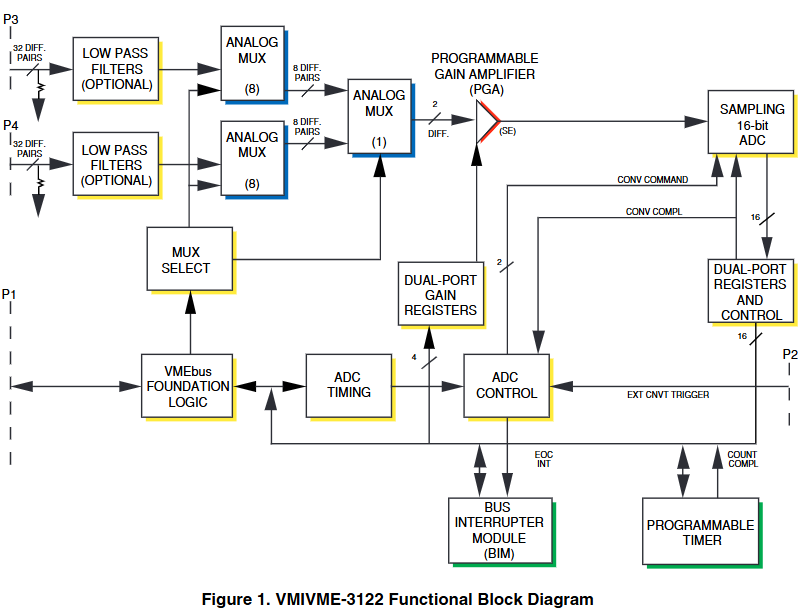
VMIVME-3122 is a high-performance 16 bit analog-to-digital converter that supports 64 differential or single ended wide range (± 250 mV to ± 10 V) analog inputs, suitable for fields such as factory automation and instrumentation, process control, laboratory instruments, machine monitoring, and data acquisition.
Core Features
Input and Conversion Performance
Supports 64, 32, or 16 differential or single ended inputs, depending on the selected option.
16 bit A/D conversion, software selectable conversion rate, high-performance option up to 100 kSPS, standard performance option up to 50 kSPS.
The software has programmable gains of 1 and 10, which can be fixed for all channels or individually programmed for each channel.
Jumper selectable A/D range: 0 to+5 V, 0 to+10 V, ± 2.5 V, ± 5 V, and ± 10 V.
Scanning and triggering mode
Scan modes: including AutoScan (default, continuously scans all active channels in order), Single Scan (starts a scan of all selected channels once triggered by trigger mode, stops waiting for the next trigger after completion), Random Access (selects, digitizes, and stores a single channel each time the trigger mode is enabled).
Trigger modes: There are Software Trigger (which starts the selected scanning mode by writing the software trigger address), External Trigger (which starts the selected scanning mode by receiving an external trigger through the P2 connector), and Interval Timer Trigger (which starts the selected scanning mode every time the programming time interval expires).
Data storage and access: 1024 word data buffer (16 word deep buffer x 64 channels), dual port register allows VMEbus to access and read the latest stored data at any time, buffer size and block size can be controlled through configuration control registers (CCR).
Other functions
Programmable VMEbus interrupt, which can generate interrupt requests at the end of buffer scanning or during the collection of a specific number of samples.
User programmable interval timer, with a timing interval of up to 687 seconds.
Optional low-pass filter, input with overvoltage protection.
When powered on, it starts in automatic scanning mode with a gain of 1.
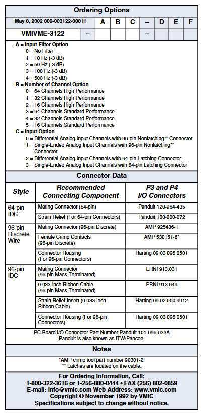
Ordering Options
Input filter options (A): 0 for no filter, 1 for 10 Hz (-3 dB), 2 for 50 Hz (-3 dB), 3 for 100 Hz (-3 dB), 4 for 500 Hz (-3 dB).
Channel quantity options (B): 0 is 64 channel high-performance, 1 is 32 channel high-performance, 2 is 16 channel high-performance, 3 is 64 channel standard performance, 4 is 32 channel standard performance, and 5 is 16 channel standard performance.
Input options (C): 0 is a differential analog input channel with a 96 pin non latch connector, 1 is a single ended analog input channel with a 96 pin non latch connector, 2 is a differential analog input channel with a 64 pin latch connector, and 3 is a single ended analog input channel with a 64 pin latch connector.
Functional feature details
VMEbus related
The address modifier response can be jumper selected as A32, A24, or A16 address space, as well as monitoring or user privileges, or both.
Compliant with VMEbus standard ANSI/IEEE STD 1014-1987 IEC 821 and 297.
Reset operation: When the system is reset or the software reset address is written, a board reset occurs. The reset operation automatically establishes default conditions, including automatic scanning mode, channel block size and data buffer determined by the selected option, gain of 1, and conversion rate of 100 kHz (the standard performance option needs to be set to 50 kSPS or lower after reset). After reset, the ADC will undergo a calibration cycle of 41 ms.
Panel indicator: The front panel LED controlled by the program lights up during the reset period and goes off through CSR.
Input characteristics
Accuracy: The maximum error is ± 0.005% reading ± 0.005% range ± 100 µ V.
Stability: Temperature drift is ± 10 PPM (ADC reading)+± 7.5 PPM (ADC range)+± 2.5 µ V, doubling the frequency in single ended applications.
Common mode/floating input protection: In the high-performance option, the low end of each input is grounded through a 22 M resistor; In the standard performance options, users must control the common mode voltage to prevent input fluctuations.
Input noise: (0.4+0.3/G) mV, where G is the PGA gain, noise is independent of filter options.
Other: The maximum input bias current is 40 nA (at zero input), and the minimum input impedance is 5 M Ω (parallel 50 pF).
Transmission characteristics
Resolution: 16 bits, no missing codes.
Channel crosstalk (DC to 1 kHz): The adjacent channels of the high-performance option (391 to 100 kSPS) are -88 dB, and the alternating channels are -110 dB; the adjacent channels of the standard performance option (50 kSPS) are -50 dB, and the alternating channels are -90 dB; the adjacent channels of the standard performance option (35 kSPS) are -90 dB, and the alternating channels are -96 dB.
Input transfer function:
E IN=E LO+E FSR × 65536N ADC, where E IN is the input voltage, E LO is the lower limit of the input range, E FSR is the full-scale input range, and N ADC is the reading of the A/D converter.
Common mode rejection: DC to 60 Hz (350 source imbalance), minimum 90 dB, typical 100 dB at gain 1; minimum 100 dB, typical 120 dB at gain 10; minimum 75 dB common mode rejection in the range of ± 2.5 V and 0 to+5 V, adjustable on-site to the same level as gain 1.
Overvoltage protection: continuous ± 35 V (power on/off), transient ± 80 V (maximum 1 second).
Integral nonlinearity: maximum ± 0.005% (compared to the optimal line), differential nonlinearity: ± 0.0015%.
Physical/Environmental Characteristics
Working temperature: 0 to+65 ° C (standard VME slot), storage temperature: -40 to+85 ° C.
Humidity: 0 to 80% relative humidity, no condensation.
Altitude: The working altitude can reach 3000 meters.
Cooling: forced air convection (standard VME slot).
Size: Double height European card (6U) board, 160 × 233.35mm.
Weight: Maximum 700 g.
Input connectors (P3, P4): can be ordered as 96 pin DIN non latch or 64 pin DIN latch.
Power requirement: Maximum 7.0 A at+5 VDC.
Mean Time Between Failures (MTBF): 135900 hours (217F).
UIOC ® Support and compatibility signal conditioning board
UIOC ® Support: Used as a monitoring device in UIOC, UIOC is programmed to scan all 64 channels and set to AutoScan mode during initialization. Users can use UCLIO ™ Language settings allow programmable channel gain and command UIOC to retrieve data from any or all channels, creating and storing channel gain and offset correction factors through a menu driven calibration process.
Compatible signal conditioning board
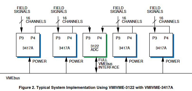
VMIVME-3417A: 16 channel isolated signal conditioning board with optional current loop termination, providing a full-scale input range of ± 5 mV to ± 10 V, and optional two pole low-pass input filter (cut-off frequency 4, 40, or 400 Hz).
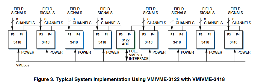
VMIVME-3418:8 channel strain gauge and RTD isolation signal conditioning board, providing a full-scale input range of ± 5 mV to ± 10 V, with optional low-pass input filter (cut-off frequency 4, 40, or 400 Hz).
VMIVME-3419:32 channel signal conditioning board, with programmable gain and built-in test (BIT), accepts a full range input range of ± 5 mV to ± 10 V according to the selected gain of the A/D board, optional low-pass filter (cut-off frequency 4, 40, 400 or 4 kHz) and current loop terminal input resistance.
- YOKOGAWA
- Reliance
- ADVANCED
- SEW
- ProSoft
- WATLOW
- Kongsberg
- FANUC
- VSD
- DCS
- PLC
- man-machine
- Covid-19
- Energy and Gender
- Energy Access
- Renewable Integration
- Energy Subsidies
- Energy and Water
- Net zero emission
- Energy Security
- Critical Minerals
- A-B
- petroleum
- Mine scale
- Sewage treatment
- cement
- architecture
- Industrial information
- New energy
- Automobile market
- electricity
- Construction site
- HIMA
- ABB
- Rockwell
- Schneider Modicon
- Siemens
- xYCOM
- Yaskawa
- Woodward
- BOSCH Rexroth
- MOOG
- General Electric
- American NI
- Rolls-Royce
- CTI
- Honeywell
- EMERSON
- MAN
- GE
- TRICONEX
- Control Wave
- ALSTOM
- AMAT
- STUDER
- KONGSBERG
- MOTOROLA
- DANAHER MOTION
- Bentley
- Galil
- EATON
- MOLEX
- Triconex
- DEIF
- B&W
- ZYGO
- Aerotech
- DANFOSS
- KOLLMORGEN
- Beijer
- Endress+Hauser
- schneider
- Foxboro
- KB
- REXROTH
- YAMAHA
- Johnson
- Westinghouse
- WAGO
- TOSHIBA
- TEKTRONIX
- BENDER
- BMCM
- SMC
- HITACHI
- HIRSCHMANN
- XP POWER
- Baldor
- Meggitt
- SHINKAWA
- Other Brands
- UniOP
- KUKA
- IBA
- Beckhoff
- ADLINK
-
Beckhoff CX1100-0910 - Power Supply Module
-
Beckhoff C5210-0010 - Communication Module C5210
-
BECKHOFF KL1352 - Bus Terminal SET OF 2 FREE FAST SHIP
-
Beckhoff EL3058 - 8 x analog input single ended 4...20mA 85惟 shunt 12bit
-
Beckoff CX1100-0920 - UPS Module 24VDC (US SELLER) * *
-
BECKHOFF C6920-0000 - C69200000 PLC Moudule
-
Beckhoff CX5120-0115 - CPU controller module CX5120-0115
-
Unknown 15F5C1E-Y50A - Of Frequency Converters
-
Beckhoff AX5118-0000-0200 - Servo Drive HTP0
-
BECKHOFF AX5106-0000-0200 - Servo Drive
-
Beckhoff CX5240-0175 - Module (free) #U2327D YG
-
Beckhoff CP6607-0001-0000 - Compact PC Panel Economy Installation Operator 5,7 "
-
Beckhoff EP3744-0041 - 2022 EP37440041 Module
-
Beckhoff CP6209-0001-0020 - 6.5" PC Touch Screen Control Panel 24VDC
-
Beckhoff CX9020-0111 - /U900 +8x+2xEL3121+1x EL9410+3xEL1008+1x EL2008 Set
-
Beckhoff C6525-1030-0050 - Industrial PC
-
Beckoff CX1100-0920 - UPS Module 24VDC (US SELLER)
-
Beckhoff CX5010-0120 - CX5010 Processor Intel Atom Z510 B24
-
Siemens 6FC5203-0AF04-1BA1 - Operation Panel
-
Beckhoff CX5230-0175 - / 000029724 Embedded PC / Industrial PC on Rail
-
Beckhoff CP3916-0000 - industrielles Anzeige- und Bedienterminal
-
BECKHOFF CX1500-M310 - CX1000-N000 CX1000-0011 CX1000-C00L CX1100-0002 PLC Module
-
Beckhoff EL1872 - 16-channel digital input terminal
-
BECKHOFF EP2318-0001 - module
-
Beckhoff CX9020-0110 - Basic CPU Module
-
Beckhoff EL2564 - EtherCAT Terminal, 4-channel LED output, 5鈥?8VDC, 4A, RGBW
-
Beckhoff CX5130-0155 - /000105637 Automation Embedded PC
-
B&R 400 - Power Control Panel Rev D0 24 VDC
-
Beckhoff CX2020-0155 - module
-
Beckhoff CX9020-0115 - PLC Module
-
BECKHOFF EL6695 - PLC EL 6695
-
BECKHOFF EL7047 - PLC Modules
-
Beckhoff CX1000-0012 - Control HW 2.2 + CX1500-M310 + CX1000-C00L + CX1100-0002+
-
Beckhoff C6920-1039-0030 - control cabinet industrial PC CPU Celeron 1.90 GHz, 2 cores
-
BECKHOFF CX1100-0910 - PLC Module#
-
Beckhoff IL2301-B318-0000 - Coupler Box 4 Channel Digital Input |
-
Beckhoff CX7080 - Module
-
Beckhoff C6930-0060 - Industrial PC
-
Beckhoff CP7902-1060-0000 - Touchscreen 15 " CP7902
-
beckhoff CX9020-0111 - Controller module or UPS
-
Beckhoff CX8091 - PLC Module CX8091
-
Beckhoff C6640-1008-0030 - Control Cabinet Industrial PC
-
BECKHOFF CX1100-0920 - module
-
Beckhoff C9900-M921 - see pictures
-
BECKHOFF CP6829-0001-0000 - Touch Panel
-
BECKHOFF C6930-0060 - Industrial Computer
-
BECKHOFF CX8050 - PLC module
-
Beckhoff CP6202-0021-0020 - Touch Screen #
-
BECKHOFF AM3031-0C20-0000 - SERVO MOTOR
-
Unknown BCH1302N11A1C - Servo motor
-
Beckhoff EL2502 - 2-channel pulse width output terminal
-
Beckhoff EL6731 - Profibus Master / *Rev: 0025
-
Beckhoff CP3918-0010 - Control Panel
-
BECKHOFF CP2915-0010 - [24 MONTH WARRANTY] Control Panel
-
Beckhoff AX5203-0000-0202 - Servo Drive
-
Schneider TSXDSY64T2K - PLC OUTPUT MODULE
-
Beckhoff EP4174-0002 - Module-
-
Beckhoff IL2302-B318-0000 - Profibus Box
-
Beckhoff CP6709-0001-0000 - Touchpanel
-
BECKHOFF CX2030-0123 - Controller
-
Beckhoff CX9020-0111 - Processor Module
-
Beckhoff CX1020-0000 - CX Basic CPU Module
-
Beckhoff AX2003-AS - Servo Drive HTP0
-
Beckhoff C6240-1052-0040 - 4-086-06-3073 Industrial Computer CB1052-0003
-
Beckhoff EL1918 - 8 xTwinSAFE Input
-
Beckhoff AM8072-0R20-0000 - Servomotor
-
BECKHOFF AM8021-1B21-0000 - servo motor #T882 YS
-
Beckhoff EL6224 - 4 X Terminal IO-LINK
-
Beckhoff CX5140-0135 - embedded PC with Intel Atom processor 4 GB HW 3.6
-
Beckhoff CP7201-1000-0000 - Panel PC #
-
Beckhoff CX5130-0121 - Embedded-PC 4GB CPU Module HW 2.5 Industrial PC
-
Beckhoff AM8022-0D41-1002 - Servomotor
-
BECKHOFF CX2030-0130 - Module
-
BECKHOFF EL1872 - 16-channel digital input terminal
-
Unknown GXMMW.A203P33 - 1pc encoder
-
Beckhoff EL6631-0000 - EtherCAT Terminal 2-Port EL 6631
-
BECKHOFF C6925-0030 - Industrial Computer
-
Beckhoff CX8190 - A Module
-
BECKHOFF CX2040-0135 - CX2040-0135/000000927 CPU BASE MODULE i7 2715QE 2.1GHz --
-
BECKHOFF KL6023-0000 - Wireless adapter
-
Saia Burgess PCD7.F700 - PCD7F700 Communication Module
-
Beckhoff CX5130-0112 - CPU Module
-
BECKHOFF CX1020-N010 - CX1020-N000 CX1020-0111 CX1100-0004 EL2008 EL3064 EL4004
-
Beckhoff EP1819-0021 - A Module
-
Beckhoff CX2030-0120 - / 4gb with CX2100 0004
-
B&R X20-XC-0292 - Automation Powerlink Ethernet Bus Controller Module
-
Beckhoff BK3110 - One PLC Module
-
BECKHOFF KL3222 - PLC Module
-
BECKHOFF CX1500-M310 - CX1000-N000 CX1000-0011 CX1000-C00L CX1100-0002 PLC MODULE
-
Beckhoff CP3918-0010 - Control Panel
-
Beckhoff CX2030-0100-1002 - /4GB + CX2100 + CX2550 + CX2500-0060 + SSD
-
Beckhoff EP1816-0008 - PLC Module
-
Beckhoff CX5130-0112 - Module
-
Beckhoff Cx1500-m750 - CPU Hw: 1.4
-
BECKHOFF AX5112-0000-0200 - AX511200000200 Servo Driver
-
Beckhoff EL3751 - EtherCAT Terminal 1 Channel Analog Input Multifunction 24 Bit
-
Beckhoff CX1100-0002 - Power Supply Module
-
Beckhoff CP3916-1016-0010 - Control Panel
-
BECKHOFF CX9001-1101 - #NAME?
-
Beckhoff EP3174-0002 - EtherCAT Box Module
-
Beckhoff C6030-0070 - servo drive
-
Beckhoff CX2020-0120 - /4GB CPU, CX2100-0904, 3x EL6900, EL1904, 16GB Memory
-
BECKHOFF C6110 - BOX-PC 113608
-
BECKHOFF EK1914 - module #P
-
Beckhoff C6140 - Ipox IP-4GVI63 + CH7009A_DVI_TV + SIEMENS A5E00369843 + WD800AAJB
-
Beckhoff CX5020-0111 - controller Good quality
-
BECKHOFF C6015-0010 - / 6559380 ULTRA-COMPACT INDUSTRIAL PC ()
-
Beckhoff AX5203-0000-0200 - PLC module
-
Beckhoff EL2872 - 16-channel digital output terminal
-
BECKHOFF C3640-0000 - Panel Industrial PC 100/240VAC 128MB E0122L
-
Beckhoff CX8031 - Module
-
Beckhoff CX5020-0120-1002 - PLC module#
-
Beckhoff C6140 - M845B + SIEMENS A5E00369843 + C9900_A159_1 + AUTOMATA CAN PCI 1N
-
BECKHOFF AX5112-0000-0200 - Servo Drive*ie
-
B&R ECPA42-01 - Analog Output Module 4-Channel, +/- 10V Output Signal, 20mA Max
-
Beckhoff EL6631-0010 - PLC Module
-
BECKHOFF C6930-0070 - CONTROL CABINET INDUSTRIAL PC
-
BECKHOFF AX5112-0000-0200 - AX511200000200 Servo Driver
-
BECKHOFF EK9000 - Programmable Logic Controller Module EK9000 EK9000
-
BECKHOFF C6920-1028-0000 - Industrial computer
-
Beckhoff CX2030-0120 - controller Module
-
Beckhoff BX8000-0000 - Bus Terminal Controller HW 4.4
-
B&R 3NC154.60-2 - Positioning Module#
-
BECKHOFF CX1020-0122 - PLC module
-
Beckhoff AM3032-0D40-0000 - Servo Motor
-
BECKHOFF CX5020-0111 - CPU Module CX5020-0111
-
Beckhoff CB1051 - G5 Motherboard
-
BECKHOFF KL2641 - 1-channel relay output terminal

K-JIANG

Add: Jimei North Road, Jimei District, Xiamen, Fujian, China
Tell:+86-15305925923