

K-WANG


YOKOGAWA VP6F1900/1905 Control Function (A2FV70 Dedicated)
YOKOGAWA VP6F1900/1905 Control Function (A2FV70 Dedicated)
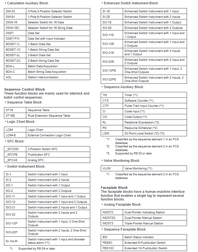
Classification and specifications of core functional blocks
1. Basic functional blocks (7 categories)
Functional block type, core usage, representative model and key characteristics
Continuous process control PID (standard PID), PID-STC (self-tuning PID), ONOFF (two position switch control), FF-PID (fieldbus PID), etc
Compute block signal operations and logical processing ADD (addition), SQRT (square root), AND (logical AND), Calcu (general computing), etc
Sequence control block interlocking and batch control ST (sequence table), LC (logic diagram), SIO-11E (enhanced switch instrument), TMF (timer), etc
Panel block multifunctional block unified label display INDST3 (three pointer manual station), BSI (batch status indication), HAS3C (mixed manual station), etc
Unit instrument block, whole unit equipment control, UTAS (analog unit instrument), UTPB-N (non resident 5-key unit instrument), etc
Valve mode monitoring block (optional) Valve switch status monitoring VPM64 (64 points) - VPM512A (512 points with alarm)
Off site Block (optional) Refinery Off site Mixing/Shipping Control FSBSET (batch setting), BLEND (mixing master control)
2. Featured functional blocks (3 types of core extensions)
Functional block type, core characteristics, applicable scenarios
ZWOPID (Wireless PID Compensation) is compatible with wireless field devices and provides PID control for stable process response in wireless communication scenarios when data packets are lost
YS instrument block compatible with YS series controllers/manual stations/total meters YS series instrument integrated control
Enhanced switch instrument block supports 1-2 input/output channels, including single trigger output type complex interlocking logic control
I/O function and communication support
1. Classification of I/O functions
I/O Type Core Function Signal Identification/Support Range
Process I/O on-site device signal interaction simulation I/O ≤ 1760 points, contact I/O ≤ 4096 points
Software I/O FCS internal virtual signal internal switches (% SW: 9999,% GS: 256), message output (6 types of messages including% AN/% PR)
Communication I/O subsystem data exchange% W/% X identification, supports PLC and other subsystem data access, 16 bit data volume ≤ 8000 words
Fieldbus I/O fieldbus device access% Z identification, compatible with FOUNDATION fieldbus devices
2. Subsystem Communication Protocol
Supports 5 types of core communication modules and protocols, requiring corresponding hardware modules:
Serial communication: ALR111/ALR121 modules (N-IO/FIO specific)
Ethernet communication: ALE111 module (N-IO/FIO specific)
FOUNDATION fieldbus communication: ALF111 module (N-IO/FIO specific)
PROFIBUS-DP communication: ALP121 module (N-IO/FIO specific)
PROFINET communication: A2LP131 module (N-IO/FIO specific)
Application capacity and operating parameters
1. Core indicators for three types of capacity configuration
Configuration type: Standard type (C01) Extended type (C02) Large type (C03)
Number of tags (maximum) 18000 18000 18000 18000
Number of functional blocks (maximum) 5500 7000 9000
Simulate I/O points (maximum) 1760 points 1760 points 1760 points
Contact I/O points (maximum) 4096 points 4096 points 4096 points 4096 points
Control the number of drawings 200 (optional 300/400/500) 200 (optional 300/400/500)
1 second trend collection points 1024 points 1024 points 1024 points
2. Scanning cycle and database requirements
Scanning cycle:
Standard scan: 1 second (fixed)
Medium speed scanning: 200ms/500ms (can directly input 50/100/250ms), suitable for analog quantity calculation
High speed scanning: 200ms/500ms (can directly input 50/100/250ms), suitable for sequence control
Database optional area occupation:
Enhanced switch instrument/motor control/ONOFF controller: 64KB (occupied by using any function block)
Off site block: 80KB
Valve mode monitoring: 90KB
Wireless PID compensation: 120KB
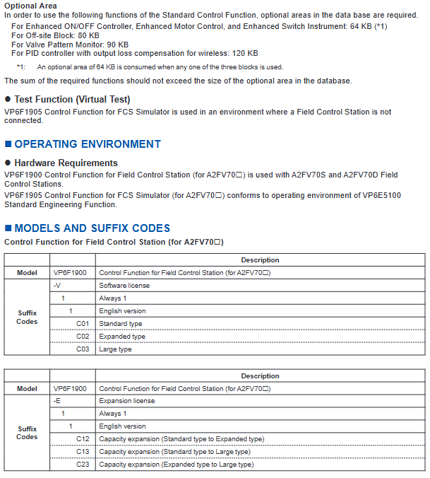
Featured features and model specifications
1. Core characteristic functions
RIO system upgrade support: Adapt to RIO system upgrade hardware, optimize application capacity and database size
N-IO module compatibility: supports integration of multiple signal types (AI/AO/DI/DO), channel level adapter expansion (such as thermocouples)
Late Binding Technology: First create control logic, determine the I/O list, and then allocate I/O through software to avoid construction delays
HART feature enhancement: Supports HART7 protocol, receives device status change notifications, shortens variable updates and device inspection cycles
2. Model and ordering specifications
Product Type Basic Model Suffix Code Description Extended License Model
On site control station control functions VP6F1900-V11C01 (standard)/- V11C02 (extended)/- V11C03 (large) VP6F1900-E11C12 (standard → extended), etc
FCS simulator control functions VP6F1905-V11C01 (standard)/- V11C02 (extended)/- V11C03 (large) VP6F1905-E11C13 (standard → large), etc
Note: The suffix "11" represents the English version, and the extended license only supports upward upgrades (not downgrades)
4. Key issues
Question 1: What are the core differences between the three capacity configurations (C01/C02/C03) of VP6F1900/1905? How to select based on project requirements?
answer
Core difference: The number of labels (all 18000) and I/O points (all analog 1760 points/contact 4096 points) for the three types of configurations are completely the same, only the number of functional blocks and the number of control drawing options are different:
Standard type (C01): 5500 functional blocks, 200 control graphics (non expandable);
Expansion type (C02): 7000 functional blocks, 200 control graphics (optional 300/400/500);
Large type (C03): 9000 functional blocks, 200 control graphics (optional 300/400/500).
Selection principle:
Small projects (≤ 5500 functional blocks, ≤ 200 control graphics): Choose C01 standard type;
Medium sized project (function blocks 5501-7000, control drawing needs to be expanded): choose C02 expansion type;
Large scale projects (7001-9000 functional blocks, complex control logic): Choose C03 large type;
Possible future expansion: prioritize CO2/C03, or upgrade from C01 through an extended license.
Question 2: Features of VP6F1900 (N-IO compatibility Late Binding、 What engineering pain points does wireless PID compensation solve? What are the applicable scenarios?
answer
N-IO compatibility function:
Pain point: Traditional I/O modules have fixed signal types and poor adaptability;
Solution: Single module supports AI/AO/DI/DO multi signal types, and channel level adapters can be used to extend special signals (such as thermocouples);
Applicable scenarios: New projects with complex signal types that require flexible expansion.
Late Binding Technology:
Pain point: Change in I/O list leads to rework of control logic and delays in construction;
Solution: First complete the control logic design, determine the I/O list, and then allocate I/O through software;
Applicable scenario: Engineering projects with frequent changes in I/O requirements.
Wireless PID compensation (ZWOPID):
Pain point: Wireless communication is prone to packet loss, leading to unstable PID control;
Solution: Built in packet loss compensation mechanism, stable process response when restoring communication;
Applicable scenario: PID control loop using wireless field devices (such as remote tank pressure/liquid level control).
Question 3: What are the I/O types and communication protocols supported by VP6F1900? How to integrate with third-party subsystems such as PLC and fieldbus devices?
answer
Supported I/O types:
Process I/O: Analog quantity (≤ 1760 points), contact quantity (≤ 4096 points);
Software I/O: Internal switches (% SW/% GS), Category 6 message outputs (% AN/% PR, etc.);
Communication I/O: Subsystem data access (% W/% X, 8000 words of 16 bit data);
Fieldbus I/O: FOUNDATION fieldbus device (marked with% Z).
Third party integration implementation method:
PLC integration: Supports protocols such as Modbus through ALR111/ALR121 (serial port), ALE111 (Ethernet), ALP121 (PROFIBUS-DP) modules;
Fieldbus device integration: Connect to FOUNDATION fieldbus devices through ALF111 module, and achieve data exchange through FF series functional blocks (FF-AI/FF-PID, etc.);
PROFINET device integration: Connect to the PROFINET subsystem through the A2LP131 module to achieve data reading, writing, and control.
- YOKOGAWA
- Reliance
- ADVANCED
- SEW
- ProSoft
- WATLOW
- Kongsberg
- FANUC
- VSD
- DCS
- PLC
- man-machine
- Covid-19
- Energy and Gender
- Energy Access
- Renewable Integration
- Energy Subsidies
- Energy and Water
- Net zero emission
- Energy Security
- Critical Minerals
- A-B
- petroleum
- Mine scale
- Sewage treatment
- cement
- architecture
- Industrial information
- New energy
- Automobile market
- electricity
- Construction site
- HIMA
- ABB
- Rockwell
- Schneider Modicon
- Siemens
- xYCOM
- Yaskawa
- Woodward
- BOSCH Rexroth
- MOOG
- General Electric
- American NI
- Rolls-Royce
- CTI
- Honeywell
- EMERSON
- MAN
- GE
- TRICONEX
- Control Wave
- ALSTOM
- AMAT
- STUDER
- KONGSBERG
- MOTOROLA
- DANAHER MOTION
- Bentley
- Galil
- EATON
- MOLEX
- Triconex
- DEIF
- B&W
- ZYGO
- Aerotech
- DANFOSS
- KOLLMORGEN
- Beijer
- Endress+Hauser
- schneider
- Foxboro
- KB
- REXROTH
- YAMAHA
- Johnson
- Westinghouse
- WAGO
- TOSHIBA
- TEKTRONIX
- BENDER
- BMCM
- SMC
- HITACHI
- HIRSCHMANN
- XP POWER
- Baldor
- Meggitt
- SHINKAWA
- Other Brands
- UniOP
- KUKA
- IBA
- Beckhoff
- ADLINK
-
ALPHA WIRE 1636-RD001 - Hook-Up Wire
-
FANUC A06B-6078-H211#H501 / A06B6078H211H501 - Servo Amplifier Module
-
Alpha H47016 / CA400 - 400W Switching Power Supply Unit
-
Alpha Wire 2821/2 WH001 - Multi-Conductor Communication Control Cable
-
Wittenstein Alpha SP 100S-MF2-25-1E1-2S - Planetary Gearbox Reducer
-
FANUC A06B-6090-H008 / A06B6090H008 - Servo Power Supply Module
-
Alpha Wire 2821/2 WH001 - Multi-Conductor Communication Control Cable
-
NOVOTRON / Alpha NBL2-0080-45-3-320 T0B + SP075-MF1-3-031-000 - Servo Motor with Planetary Gearbox
-
Alpha 0100044-001 CXRF 48/4.6KW - Rectifier Module
-
Lambada-TDK / Alpha YM-00-470B / AMAT 50513215200 - 600W Power Supply Unit
-
FANUC A06B-6290-H122 - Alpha iSV 10HV-B 3-Axis Servo Amplifier Drive
-
Alpha SP 140S-MF1-5-1/1-2S - Planetary Gearbox Reducer
-
Wittenstein Alpha SP 100S-MF1-5-1K1-2S - Planetary Gearbox Reducer
-
Wittenstein Alpha LP 120Z-MF1-10-1/1-3S-INF - LP Series Planetary Gearbox
-
Wittenstein Alpha LP 090-M01-7-111-000 / Schneider - Planetary Gearbox with Servo Motor
-
Alpha TP 050-MX1-7-450-000 - Gearbox Reducer
-
Fanuc A06B-0377-B577#7000 - AC Servo Motor Alpha M2.5/3000
-
ALPHA WIRE 1705-SL001 - Hook-Up Wire
-
ALPHA WIRE 1953/3T-BK003 - Hook-Up Wire
-
ALPHA WIRE 5855/7-SL001 - Hook-Up Wire
-
ALPHA WIRE 2158-NA005 - Hook-Up Wire
-
Wittenstein Alpha TP 025S-MF1-7-0G0-2S - Planetary Gearbox
-
ALPHA WIRE 5356C - 37 Conductor 20AWG Foil & Braid Shield Cable
-
Wittenstein Alpha NP 025S-MF1-5-1G1-1S - Planetary Gearbox
-
Allen Bradley / Alpha N-3412-2-H00AA / LP 120-M02-100-111-000 - Servo Motor with Planetary Gearbox
-
FANUC A06B-6089-H204 - Alpha Series Servo Amplifier Module
-
Man Diesel & Turbo 3157168-7 - Alpha Lubricator Sbu
-
FANUC A20B-2100-0742 - ALPHA ia Servo Control Board
-
ALPHA ALPHA6000E-31R5GB - Frequency Inverter Drive Power Converter
-
Alpha Industries G287775-1 / 5985-01-341-9652 - Variable Attenuator
-
FANUC A06B-6124-H206 - Alpha iSV Servo Amplifier Module
-
Wittenstein Alpha NP 025S-MF1-5-1G1-1S - Planetary Gearbox
-
NOVOTRON / Alpha NBL2-0080-45-0-320-B-S-A + SK060-MF1-3-031-000 - Servo Motor with Alpha Gearbox
-
FANUC A20B-2100-0742 - ALPHA ia Servo Control Board
-
Honeywell CK65-L0N-BLC210F / CK65 - Mobile Computer Barcode Scanner
-
Wittenstein Alpha TK+ 004S-MF2-12-5B1-1S10 - Right Angle Gearbox
-
FANUC A20B-2100-0742 - ALPHA ia Servo Control Board
-
Rexroth MSK071E-0450-NN-M1-UG1-NNNN - 3-Phase AC Motor with Alpha Reducer
-
JAVAD ALPHA2 - GPS Receiver GrAnt G3
-
GROSCHOPP / Alpha WK 1621309 / EK 66-45 NR + TP 010-MF2-61-030-000 - Motor with Alpha Gearbox Construction
-
ALPHA WIRE 5060C-SL005 - Multi-Conductor Cable Wire
-
ALPHA B10 K X 2 T80887 - Potentiometer
-
Alpha 400W J40005 - Switching Power Supply Unit
-
FANUC A20B-1007-0650 - ALPHA Power Supply Module Board
-
Eberline HP-100B - Gas Proportional Alpha Beta Probe GM Geiger Counter
-
ALPHA WIRE 5858-BK001 - Single Conductor Hook-Up Wire
-
FANUC A06B-6127-H103 - Alpha I AiSV-20HV Servo Amplifier Module
-
VIASYS / CareFusion SOMNOSTAR CEPHALO PRO - Portable EEG Neurodiagnostic Sleep System
-
DSI Surgical Instruments Universal - Dental Implant Abutment Surgical Instruments Kit
-
FANUC A06B-6078-H211#H501 / A06B6078H211H501 - Servo Amplifier Module
-
Fanuc A06B-6089-H209 - Alpha Series Servo Amplifier Module
-
Generic / DSI Straight Anatomic Plastic Adapter Head + Screw Hex - Dental Implant Fixture
-
FANUC A20B-1006-0680 - ALPHA Power Supply Module Board
-
B&L Biotech Alpha II - Endodontic Starter Kit
-
FANUC A06B-0166-B088 C009A5653 - AC Servo Motor
-
ALPHA WIRE 74010-BK002 - Multi-Conductor Cable Wire
-
Wittenstein Alpha SPK 100-MF2-10-041-000 - Gear Box Reducer Ratio 10:1
-
Alpha Getriebebau 10-FL-M1-5 - 10:1 Ratio 7/8 Inch Shaft Gear Reducer
-
ALPHA WIRE 2172-SV005 - Multi-Conductor Cable Wire
-
Aloka UST-5410 - Linear Array Probe Compatible Transducer
-
Alpha Xtra-Guard 1 SupraShield - Multiconductor Cable 16 AWG 2 Conductor
-
ALPHA ALPHA7000E-37R5GB/3011PB - Frequency Inverter Drive Power Converter
-
SIEMENS / Alpha 1FT5066 / SP 100 ROD 426B - Servo Motor with Actuator
-
FANUC A06B-6089-H210 / A06B6089H210 - Servo Amplifier Module
-
LAMBDA ALPHA 600W H60553 - Switching Power Supply Unit
-
Alpha 400W J40071A - Switching Power Supply Unit
-
Hyva Alpha Series FC A4.5-3-98-K6-1DA-HC / 70593139 - Dump Body Hydraulic Cylinder
-
ALPHA WIRE 1293C-SL001 - Multi-Conductor Cable Wire
-
NSS Galaxy / Alpha 20 and 16 - Floor Strip and Wax Slow Speed Buffer and Wet Vac
-
Alpha Xtra-Guard 1 SupraShield - Multiconductor Cable 16 AWG 2 Conductor
-
ALPHA ALPHA6000-3015JB - Frequency Inverter Drive Power Converter
-
Densei-Lambda MA4000591A/ME Alpha 400 / MV6500271A Alpha II-650 - Power Supply Unit
-
Wittenstein Alpha SP 140G-MF2-28-0E1-2S-PGG - Planetary Gear Reducer
-
FANUC ROBOCUT ALPHA-1iC - CNC Wire EDM Machine
-
Fanuc A06B-6081-H101 - Alpha Series Power Supply Module PSMR-1
-
ALPHA WIRE 5855-BL001 - Hook-Up Wire
-
Wittenstein Alpha SPK 100-MF2-20-141-000 - Right Angle Gear Reducer 20:1 Ratio
-
LNS ALPHA SL65-S - Bar Feed System
-
ALPHA WIRE 5356C - 37 Conductor 20AWG Foil & Braided Shield TC Shield Cable
-
TDK-Lambda / Alpha H60552 - 600W Switching Power Supply Unit
-
Bruker Alpha - Infrared Spectrometer FTIR Instrument
-
Wittenstein Alpha SP 060S-MF1-7-0B1-2S - Planetary Gearbox Reducer
-
Digital Alpha VME 5/480 - VME SBC Motherboard CPU Board
-
Glentek Alpha Series - Digital Brushless Servo Amplifier Drive
-
Wittenstein Alpha TPM 004S-021M-6KB1-053B-G6 - Rotary Servo Actuator
-
Wittenstein Alpha TP 110-MF2-61-031-000 / 20009377 - Planetary Gearbox Reducer
-
Emerson Alpha 1800 24 60 / 5070800001 - Rectifier Power Module
-
Fanuc A06B-0377-B577#7000 - AC Servo Motor Alpha M2.5/3000
-
Novotron / Alpha NBL2-0080-45-3-320 T0B + SP075 - Servo Motor with Alpha Gearbox
-
Alpha & Omega Semiconductor AOD442 - N-Channel MOSFET Reel Surface Mount
-
Alpha Wire 2156-NA005 - Hook-Up Wire Cable
-
Sankyo 15AD-04277R-LR3VW1 - Rotary Indexer with Motor
-
Wittenstein Alpha TP025S-MF1-7-0G0-2S - Planetary Gearbox i=7
-
Fanuc A20B-2001-0950 - Control Circuit Board PCB
-
TDK-Lambda / Alpha H60553 - 600W Switching Power Supply Unit
-
Alpha Wire 391845-WH001 - Hook-Up Wire Cable
-
Wittenstein Alpha SPK 100-MF2-10-041-000 - Gear Box Reducer Ratio 10:1
-
Novotron / Alpha NBL2-0080-45-0-320-B-S-A + SK060 - Servo Motor with Alpha Gearhead
-
Wittenstein Alpha TP050S-MA2-27.5-0G1-2S - Planetary Gearbox Reducer
-
Fanuc A06B-6096-H305 - Alpha Servo Amplifier Module
-
TDK-Lambda / Alpha H47006 / CA400 - 400W Switching Power Supply
-
Wittenstein Alpha SPK140 MF2-10-051-000 - Bevel Planetary Gearbox Reducer
-
Fanuc A06B-6117-H205 - Alpha iSV Servo Amplifier Module
-
Fanuc A20B-1007-0650 - Alpha Power Supply Module Board PCB
-
Alpha Wire 2248C-SL005 - Multi-Conductor Cable Wire
-
Alpha Wire 6829-BK001 - Hook-Up Wire Cable
-
Wittenstein Alpha SPK+100S-MF2-25-1E1-1K01 - Right Angle Planetary Gearbox Reducer
-
MAN B&W 99100724 - Maintenance Tools Set for Alpha Lubricator
-
Tokyo Electron (TEL) A3619-9215E / Vexta - Carrier Transfer Assembly
-
Tokyo Electron (TEL) Alpha 8 Auto Shutter 200mm - Diffusion Furnace Auto Shutter Assembly
-
Fanuc A06B-6089-H105 - Alpha Series Servo Amplifier Module
-
Aikoku Alpha EZ Amplifier Type Z - Servo Amplifier Drive
-
Fanuc A06B-6096-H204 - Dual Axis Alpha Servo Amplifier Module
-
Ferrocontrol / Alpha Getriebebau FMR063-04-60-RMK-B0 - Servo Controller with Gear Reducer
-
Fanuc A20B-1006-0680 - Alpha Power Supply Module Board PCB
-
Wittenstein Alpha SP 140S-MF1-5-0I1-2S / 20027211 - Servo Speed Reducer Gearbox
-
Stanley / Alpha 21A108721 - QMP Controller Unit
-
TDK-Lambda / Alpha J40071A - 400W Switching Power Supply Unit
-
Fanuc A06B-0235-B300 - AC Servo Motor Alpha iFS 8/4000
-
Tokyo Electron (TEL) Alpha 8s Manifold Flange Plenum - Right Side Ports Manifold Flange
-
Fuji Frontier 570 PS1 / Alpha 650II - Power Supply Assembly
-
Tokyo Electron (TEL) WCIF-01A - T-Bawl Control Unit PCB Assembly
-
Fanuc A06B-6079-H106 - Alpha Servo Drive Amplifier Module
-
Fanuc A06B-6096-H204 - Dual Axis Alpha Servo Amplifier Module
-
Fanuc A06B-6114-H302 - Triple Axis Servo Drive Amplifier Module
-
Fanuc A06B-6110-H015 - Alpha Servo Amplifier Module
-
Hitachi Aloka Prosound Alpha 7 Premier - Diagnostic Ultrasound System
-
Alpha BC35 - Canning Line for Carbonated Beverages Beer RTD

K-JIANG

Add: Jimei North Road, Jimei District, Xiamen, Fujian, China
Tell:+86-15305925923