
K-WANG


Westinghouse WGen9500c portable generator
Power specification: 120/240V single-phase AC, frequency 60Hz, speed 3600rpm, voltage stability range 230-250V, frequency stability range 58-62Hz, suitable for most household and industrial equipment
Westinghouse WGen9500c portable generator
Detailed explanation of core product information
1. In depth analysis of technical parameters
Category parameter details note explanation
Power performance: continuous power of 9500W (9.5kW), peak power of 12500W (12.5kVA), power factor of 1.0 pure sine wave output, total harmonic distortion ≤ 23%, can drive high-power inductive loads such as air conditioners, water pumps, and power tools
Power specification: 120/240V single-phase AC, frequency 60Hz, speed 3600rpm, voltage stability range 230-250V, frequency stability range 58-62Hz, suitable for most household and industrial equipment
The engine system is a 4-stroke OHV single cylinder engine with a displacement of 457cc and a compression ratio of 8.5:1. The OHV design improves combustion efficiency and extends engine life; Forced air cooling for heat dissipation, suitable for long-term operation
Oil specification: Oil capacity 1.16 quarts (1.1 liters), recommended SAE 10W-30 (temperature -15~40 ℃); In cold environments (<-10 ℃), 5W-30 can be used, and API SJ or higher grade four stroke engine oil should be used. It is strictly prohibited to use two-stroke engine oil or mixed engine oil
The fuel system has a tank capacity of 6.6 gallons (25 liters) and is compatible with unleaded gasoline grades 87-93. E15/E85 ethanol gasoline is prohibited when the ethanol content is ≤ 10% (which can easily cause corrosion and blockage of the fuel system); Under full fuel condition, 50% load can run for 12 hours
Remote start (effective distance of 30 meters), electric start (12V DC motor), manual start (emergency backup). Remote start supports one key start stop, and electric start requires 12V lead-acid battery power supply (factory standard)
Physical characteristics and dimensions (length x width x height): 86.4 x 63.5 x 78.7cm, net weight 113.4kg, equipped with a retractable transport handle and large-sized rollers, capable of short distance transportation by a single person; The tripod design ensures stable placement
2. Analysis of core components and control panel
(1) Core component functions
Engine compartment: Built in 457cc OHV engine, including air filter, spark plug, muffler, spark arrester (fireproof star filter), engine cylinder block with heat sink to enhance heat dissipation.
Fuel system: large capacity fuel tank (with fuel gauge), fuel valve, fuel filter (sedimentation cup type), carburetor. The fuel valve can be closed to cut off the fuel supply for long-term storage.
Power generation system: permanent magnet synchronous generator with stable output; Equipped with main circuit breaker (overload protection) and GFCI socket (leakage protection).
Safety components: Carbon monoxide (CO) sensor (installed on the side of the body, real-time monitoring of concentration, shutdown if exceeding the standard), low oil sensor (automatic shutdown when the engine oil is below the threshold), overheating sensor (shutdown when the cylinder body temperature is too high).
(2) Control panel full analysis
Component Name Function Description Operation Points
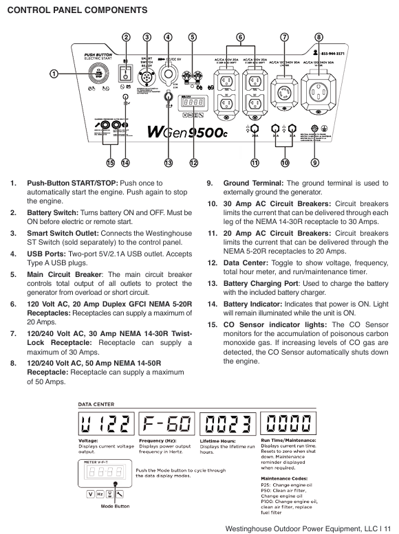
The data center (LCD screen) displays voltage, frequency, cumulative operating time, and maintenance reminder codes. Press the "MODE" button to switch the display content; Maintenance reminder codes (P25/P50, etc.) need to be processed periodically
Two 120V 20A GFCI sockets output 120V AC power with leakage protection. The maximum load of a single socket is 2400W. The plug should be fully inserted and the waterproof cover should be closed after use
120/240V 30A locking socket (1) outputs mixed voltage, suitable for high-power equipment (such as air conditioning, water pump) with a maximum load of 7200W, requires the use of a dedicated 30A locking plug, and prohibits the use of ordinary plugs for switching
120/240V 50A locking socket (1) outputs mixed voltage, suitable for multiple devices to supply power simultaneously (such as RV camping), with a maximum load of 12000W, requiring 50A dedicated cables, and a total power not exceeding 9500W
5V/2.1A USB ports (2) for charging small electronic devices such as mobile phones and tablets, with a total output current of ≤ 4.2A, to avoid charging multiple high-power electronic devices simultaneously
START/STOP button for electric start/stop control. Press the start button for 2 seconds and the stop button for 1 second; Press and hold the emergency stop button for 3 seconds
The battery switch controls the opening of the battery power supply circuit before starting, and closes it after stopping (it needs to be disconnected for long-term storage)
The fuel valve switch controls the fuel supply to open (ON) before starting and close (OFF) after stopping. It should be kept closed for long-term storage
Adjust the air intake volume with the throttle knob (only used when manually pulled to start). Close (push in) when starting the cold engine, and open (pull out) when the hot engine or stable operation is achieved
After the GFCI reset button leakage protection trips, it is necessary to investigate the cause of the leakage before resetting to ensure that the equipment has no faults
When the main circuit breaker is overloaded, it will automatically trip. After cutting off the main power supply and tripping, the load needs to be reduced. Press the circuit breaker to reset
The CO alarm indicator light (red) lights up when the CO concentration exceeds the standard. At the same time, the generator needs to be stopped and moved to a ventilated area. After checking the environment, it can be restarted
Safety operation standards (including risk avoidance)
1. Environment and placement safety
Core requirements for placement:
Only use in fully open and well ventilated outdoor areas, at least 20 feet (about 6 meters) away from doors, windows, ventilation openings, tents, etc., to prevent carbon monoxide emissions from entering indoors.
Place on a hard, horizontal surface, avoiding tilting (angle ≤ 5 °), to prevent fuel leakage or uneven oil lubrication from causing engine wear.
At least 5 feet (about 1.5 meters) of heat dissipation space should be reserved around the fuselage, away from flammable materials such as hay, wood, paint, gasoline, etc. The exhaust port should face unmanned areas.
Environmental limitations and responses:
Operating temperature range: 5 ° F (-15 ° C) to 122 ° F (50 ° C). If it is below -15 ° C, it is necessary to replace the winter specific oil (5W-30) and keep the battery warm (to avoid power loss).
Prohibited scenarios: rainy, snowy, or damp ground (to prevent electric shock); Dust and corrosive gases (such as salt spray at the seaside and chemical plant areas) can easily cause component corrosion and blockage.
Extreme weather: In rainstorm days, a temporary canopy (not sealed, ensure ventilation) shall be built to avoid rain splashing the engine and control panel.
2. Fuel safety operation
Preparation before refueling:
Turn off the engine and wait for at least 2 minutes for it to cool down (the exhaust pipe temperature can reach over 400 ℃, which can easily ignite the fuel).
Clean the oil and dust around the fuel tank cap to prevent impurities from entering the fuel tank; Prepare a qualified fuel can and do not pour it directly from a bucket.
Refueling operation specifications:
Slowly add fuel, with the fuel level not exceeding the red limit ring inside the fuel tank (with 5-10% expansion space reserved), to avoid fuel spillage during high temperatures.
If fuel overflows, immediately wipe it clean with a dry cloth and wait for the fuel to completely evaporate before starting the engine (do not ignite immediately).
Fuel storage and handling:
Backup fuel should be stored in a compliant fuel container, in a well ventilated, cool, and away from sources of ignition. The storage time should not exceed 3 months (with the addition of fuel stabilizers, it can be extended to 6 months).
Degraded fuel must be handed over to professional institutions for recycling, and it is prohibited to dump it indiscriminately (which pollutes the environment and is flammable).
Forbidden operation: Do not refuel while the engine is running; Do not use fuel to clean the body or components; Do not place fuel containers on the generator or near heat sources.
3. Electricity safety regulations
Extension cable selection:
Outdoor dedicated, undamaged, and well grounded three core cables must be used, and the cable specifications must match the load:
20A load (such as small electric tools): Use a 12 gauge cable with a length ≤ 50 feet; 14 gauge cable, length ≤ 25 feet.
30A load (such as 3kW air conditioner): Use 10 gauge cable with a length ≤ 50 feet; Number 8 gauge cable, length ≤ 100 feet.
50A load (if multiple devices are powered simultaneously): Use gauge 6 cable with a length ≤ 50 feet.
It is prohibited to use two core ungrounded cables, damaged cables, or multiple cables connected in series (which are prone to heating and leakage).
Load access principle:
Before starting, all loads must be disconnected to avoid overload triggering protection during startup.
After the generator runs stably (no-load for 3-5 minutes), connect high-power devices (such as air conditioning and water pumps) first, and then connect low-power devices (such as lights and mobile phone chargers), with a total operating power of ≤ 9500W and a total starting power of ≤ 12500W.
The starting power of inductive loads (motors) is 3-5 times the operating power and needs to be calculated separately to avoid multiple inductive loads starting simultaneously (such as a 3kW air conditioner and a 2kW water pump, the starting power may exceed 12500W).
Grounding and grid connection requirements:
The neutral wire of the generator is connected to the metal casing of the machine body and does not require additional grounding; If it is necessary to connect to the household fixed power distribution system, a certified electrician must install an automatic transfer switch (direct grid connection is prohibited to avoid reverse power transmission to the grid).
When connecting metal shell equipment (such as power tools, water pumps), ensure that the equipment is well grounded to avoid electric leakage and shock.
Emergency handling of faults: If equipment trips, heats up, or emits odors during power consumption, immediately disconnect the load, shut down the generator, and troubleshoot (such as overload or short circuit) before use; If there is electric leakage or shock, immediately cut off the power supply and seek medical attention in severe cases.
4. Personnel safety protection
Operation protection: goggles must be worn (to prevent fuel splashing and debris from entering the eyes), gloves must be worn (to prevent oil contamination and burns); Long hair should be curled up to avoid getting caught up in moving parts.
Personnel management: Children and pets should stay away from the running generator (at least 5 feet away); Do not operate the generator when fatigued, under the influence of alcohol, or after taking medication (which affects judgment).
Emergency response:
If you experience symptoms such as dizziness, nausea, and fatigue after inhaling carbon monoxide, immediately move to fresh air and seek medical attention in severe cases (carbon monoxide is colorless and odorless, so be alert).
If burns occur (due to contact with high-temperature components such as exhaust pipes), immediately rinse the burned area with cold water, and seek medical attention in severe cases.
If a fire occurs, use ABE or BE type fire extinguishers to extinguish it (it is prohibited to directly extinguish electrical or fuel fires with water).
Complete operation process (assembly → start → run → stop)
1. First use assembly and preparation
Open box inspection:
Remove the generator and its accessories (tripod, roller, tool kit, engine oil, battery, remote control, manual).
Check that the appearance of the generator is undamaged, the components are not loose, the sockets and switches are functioning properly, and the battery is fully charged.
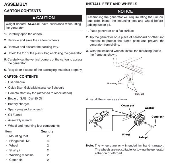
Install the tripod and roller:
Tilt the generator (ensuring that the fuel valve is closed to avoid fuel leakage), and use the accompanying bolts and wrenches to secure the tripod on both sides of the bottom of the body.
Install the roller into the slot below the tripod, tighten the fixing bolts to ensure that the roller rotates flexibly and is securely installed (which can drive the generator to test stability).
Add engine oil:
Place the generator on a level surface, open the oil filler cap on the left side of the body, and remove the dipstick.
Slowly add the recommended model of engine oil (SAE 10W-30) and check the dipstick while adding until the oil level is between the "L" (lowest) and "H" (highest) marks (not exceeding the "H" mark to avoid excessive oil accumulation and oil leakage).
Tighten the oil filler cap and dipstick, and wipe off any remaining oil with a dry cloth.
Add fuel:
Unscrew the fuel tank cap (counterclockwise) and clean the impurities around the fuel inlet.
Add unleaded gasoline with a fuel level not exceeding the red limit ring inside the fuel tank, and tighten the fuel tank cap (clockwise).
Check for leaks at the connection between the fuel tank and oil pipe. If there is any overflow, wipe it clean immediately.
Battery connection:
Find the battery quick connector on the side of the body (red positive pole, black negative pole), align the battery connector with the body connector and insert it. When you hear a "click" sound, it will lock (the connector is pre installed at the factory and does not require additional wiring).
Turn on the battery switch (to the "ON" position) and check if the control panel data center is lit up (confirm that the battery power supply is normal).
2. Startup process (detailed explanation of three startup methods)
(1) Remote start (recommended, convenient and efficient)
Preprocessing: Confirm that the fuel valve is "ON", the battery switch is "ON", all loads are disconnected, and the generator is placed for horizontal ventilation.
Start operation: Press the "START" button on the remote control for 1 second, and release it immediately after the generator starts (do not long press to avoid damaging the starter motor).
Check after startup: After the generator is started, the remote control indicator light will flash, and the data center will display voltage and frequency. Observe that the engine runs smoothly without any abnormal noise.
Cold machine regulation: If the cold machine is started, the generator may run at high speed and wait for 3-5 minutes for the speed to stabilize (automatic regulation).
(2) Electric start (used when there is no remote control or when the remote control fails)
Preprocessing: Same as remote control startup, ensure that all switch positions are correct and the load is disconnected.
Start operation: Press the "START/STOP" button on the control panel for 2 seconds, and release it after the engine starts; If it fails to start once, try again after a 30 second interval (to avoid overheating of the starting motor).
Fault handling: If the startup fails 3 times, check the battery level (possibly low), whether the fuel is sufficient, and whether the spark plug is normal.
(3) Hand pulled start (emergency backup, used when the battery is low)
Preprocessing: Close the air door (push in the air door knob), turn on the fuel valve, turn off the battery switch (no power supply required), and disconnect the load.
Start operation:
Press and hold the generator body with one hand (to prevent vibration displacement), and hold the starting rope handle with the other hand. Slowly pull until you feel an increase in resistance (piston compression stroke), then quickly and forcefully pull the handle.
After starting the engine, slowly return the handle (to avoid rebounding and hitting the body) and gradually open the air door (pull out).
Hot engine start: If the engine has been preheated, there is no need to close the air door, simply pull the start rope.
(4) Stable process after startup
Run without load for 3-5 minutes, allow the engine and generator to fully warm up, observe the data center: voltage 230-250V, frequency 58-62Hz, no fault indicator light on (CO alarm light, low fuel alarm light, etc. are all off).
Check engine sound: The sound is uniform during normal operation and there is no abnormal noise (such as knocking or whistling); If there is any abnormal noise, stop the machine immediately for inspection.
Load connection: According to the principle of "high power first, low power later", connect the devices one by one, ensuring that the plug is fully inserted during connection to avoid loosening and heating.
3. Monitoring and regulation during operation
Real time monitoring points:
Data center: Regularly check voltage, frequency (fluctuation range should not be too large), and cumulative operating time (remind maintenance cycle).
Indicator lights: CO alarm light, low oil alarm light, overheating alarm light, overload alarm light should all be turned off. If they are turned on, follow the fault handling process.
Fuel gauge: Observe the remaining fuel level and replenish it in a timely manner (to avoid shutting down due to running out of fuel).
Adjustment operation:
If the overload alarm (circuit breaker tripping) is caused by excessive load, immediately disconnect part of the load, press the circuit breaker reset button, and then reconnect.
If the engine speed fluctuates during operation, it may be due to insufficient fuel supply or clogged air filter. Check if the fuel valve is fully open and if the air filter is clean.
Long term operation (exceeding 2 hours) requires regular checks of engine temperature (with no abnormal overheating on the side of the body) to ensure good heat dissipation.
4. Shutdown process (operating in different scenarios)
(1) Normal shutdown
Disconnect all loads (unplug or turn off the device switch).
Run the generator without load for 3-5 minutes to cool down the engine and generator (to avoid direct shutdown due to high temperatures causing carbon buildup).
Press the "START/STOP" button on the control panel for 1 second or the "STOP" button on the remote control to shut down the engine.
Turn off the battery switch (OFF) and fuel valve (OFF).
Close all waterproof covers of sockets and cover with dust covers (if not used for a short period of time).
(2) Emergency shutdown (fire, leakage, abnormal noise, etc.)
Press and hold the "START/STOP" button on the control panel for 3 seconds to force a shutdown (without disconnecting the load).
Follow up processing: Investigate the cause of the malfunction (such as fuel leakage, engine noise), eliminate the fault before use, and prohibit restarting without troubleshooting.
(3) Long term shutdown (exceeding 1 month)
Disconnect the load according to the normal shutdown process and run it without load for 1 minute.
Close the fuel valve and allow the engine to continue running until the fuel runs out and automatically shuts down (to avoid fuel deterioration and blockage in the carburetor).
Disconnect the battery connection (unplug the quick connector), fully charge the battery and store it separately (to avoid damage due to low battery).
Clean the dust and oil stains on the surface of the generator, check the condition of the air filter and spark plug, and clean them if necessary.
Inject 1 teaspoon of new engine oil into the cylinder and pull the starting rope 3-5 times (without ignition) to evenly distribute the oil on the cylinder wall (rust prevention).
Cover with a dust cover and store in a dry, ventilated, and cool room (do not store in flammable areas).
Complete maintenance process (including cycle and details)
1. Preparation before maintenance
Safety measures: Turn off the generator, disconnect the battery connection, and allow the engine to cool to room temperature (to avoid high-temperature burns); Operate in a well ventilated area and prepare tools (wrench, oil pan, funnel, wire brush, etc.).
Tool list: Phillips/Phillips screwdriver, spark plug socket wrench, oil pan, funnel, cleaning cloth, compressed air (optional), new oil, fuel stabilizer, spark plug (spare), air filter cleaning fluid.
2. Routine maintenance items (executed on a periodic basis)
Before/after each use
Cleaning: Use a dry cloth to wipe the dust and oil stains on the surface of the machine body, clean the debris on the heat sink and ventilation openings (to avoid blockage that affects heat dissipation); Check if the waterproof cover of the socket is intact.
Check:
Appearance: The components are not loose or damaged, and the oil pipes and oil pipe joints are not leaking.
Oil level: The engine oil level is between "L" and "H", the fuel gauge shows sufficient, and there is no leakage.
Battery: The connection is firm, without bulging or leakage (lead-acid batteries need to check the electrolyte level, and if it is insufficient, add distilled water).
Cable and plug: No damage or aging, and the plug has good contact.
Run every 8 hours (or after each use)
Oil level check: Add oil to the standard level (not exceeding the "H" mark).
Fuel filter inspection: Observe whether there is moisture or impurities in the sedimentation cup. If there are, unscrew the drain screw to drain it, and then tighten it again.
3. Long term storage and maintenance (over 3 months)
Preparation before storage:
Cleaning: Thoroughly wipe off dust and oil stains on the surface of the body, clean up debris from the heat sink and ventilation vents.
Fuel treatment:
Method 1 (Adding Stabilizer): Fill up with fresh fuel, add fuel stabilizer (according to the instructions), start the engine and run for 5 minutes, let the stabilizer circulate to the fuel system, and close the fuel valve and battery switch.
Method 2 (Drain Fuel): Close the fuel valve, unscrew the carburetor float drain screw, and drain the fuel; Unscrew the fuel tank drain screw, drain the fuel from the tank, and then tighten all screws.
Oil change: Change the engine oil according to the procedure (to avoid impurities in the old oil corroding the engine).
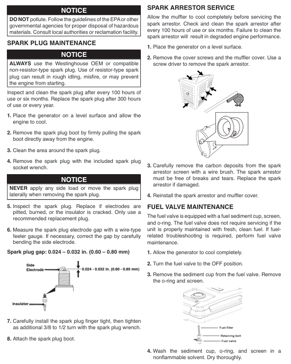
Cylinder rust prevention: Remove the spark plug, inject 1 teaspoon of new engine oil into the cylinder, pull the starting rope 3-5 times (without ignition) to evenly distribute the engine oil on the cylinder wall, then reinstall the spark plug and pull the starting rope until the piston is in compression stroke (valve closed to prevent moisture from entering).
Battery handling: Disconnect the battery, store it separately after fully charging, and recharge it every 1-2 months (to avoid battery depletion).
After storage, remove and use:
Remove the dust cover and check the appearance of the generator for any damage or debris.
Connect the battery and check the oil level (replenish if insufficient).
Add fresh fuel (do not use fuel that has been stored for too long).
According to the normal start-up process, the engine may emit smoke for a short period of time (residual oil in the cylinder), which is a normal phenomenon and will disappear after running for 1 minute.
4. Maintain taboos and precautions
Do not use flammable solvents such as fuel or banana oil to clean components (such as air filters and machine bodies) to avoid causing fires.
It is prohibited to mix different brands and models of engine oil, and it is forbidden to use two-stroke engine oil or inferior engine oil (which can damage the engine).
When replacing spark plugs, the recommended model must be used and the tightening torque should not be too high (to avoid damaging the cylinder head threads).
When cleaning the air filter, do not twist or tear the foam filter element, and do not wash the paper primary filter with water (only air blowing).
After all maintenance operations, it is necessary to ensure that the components are securely installed and the screws are tightened to avoid detachment during operation.
Deep troubleshooting of common faults (including causes and solutions)
Possible causes of malfunction, troubleshooting steps, and solutions
Unable to start: 1. Battery depletion (electric start/remote start failure); 2. Insufficient or deteriorated fuel; 3. Spark plug malfunction (carbon buildup, improper clearance, moisture); 4. The fuel valve is not open; 5. Air filter blockage; 6. Incorrect position of the air door (manual start); 7. CO sensor triggering protection: 1. Check the battery voltage (≥ 12V), and charge or replace it if it is low on power; 2. Check the fuel gauge and add fresh fuel; 3. Remove the spark plug and check its condition; 4. Confirm that the fuel valve is in the "ON" position; 5. Check if the air filter is clogged; 6. The air door of the refrigeration unit needs to be closed, and the heating unit needs to be opened; 7. Transfer to a ventilated area and wait for 10 minutes before restarting. 1. Charge or replace the battery; 2. Replace with fresh fuel; 3. Clean spark plugs, adjust clearances, air dry if damp, replace if damaged; 4. Open the fuel valve; 5. Clean or replace the air filter; 6. Adjust the position of the air door; 7. If restarting after ventilation is still ineffective, contact after-sales service
Stop immediately after startup. 1. Low oil protection (insufficient engine oil); 2. Fuel pipeline blockage; 3. The load is not disconnected; 4. Excessive concentration of CO; 5. Overheating protection (engine temperature too high) 1. Check if the low oil warning light is on and replenish the engine oil; 2. Check for blockages in the fuel filter and fuel pipes; 3. Confirm that all loads have been disconnected; 4. Transfer to a ventilated area; 5. Check if the heat sink is blocked and if the ambient temperature is too high. 1. Add engine oil to the standard level; 2. Clean the fuel filter and unclog the fuel pipe; 3. Restart after disconnecting the load; 4. Restart after ventilation; 5. Clean the heat sink and move it to a cool place for operation
Insufficient power/unstable speed during operation 1. Load exceeding the standard; 2. Insufficient fuel supply (clogged fuel filter, leaking fuel pipe); 3. Air filter blockage; 4. Spark plug carbon deposition; 5. Blockage of carburetor; 6. Ignition coil fault: 1. Check if the total load exceeds 9500W; 2. Check if there are impurities in the fuel filter and if the fuel pipe is leaking; 3. Check the status of the air filter; 4. Clean the spark plug; 5. Check if the carburetor is clogged; 6. Test the ignition coil output. 1. Reduce the load to the rated range; 2. Clean the fuel filter and repair the leaking oil pipe; 3. Clean or replace the air filter; 4. Clean or replace spark plugs; 5. Disassemble and clean the carburetor (professional operation); 6. Replace the ignition coil
No output voltage: 1. Main circuit breaker tripped; 2. GFCI socket not reset; 3. Loose wiring or poor plug contact; 4. Internal winding failure of the generator; 5. Load short circuit triggering protection 1. Check if the control panel circuit breaker has tripped; 2. Press the "RESET" button on the GFCI socket; 3. Check if the output socket and wiring are loose; 4. Disconnect all loads, restart and test; 5. Check if the connected device is short circuited. 1. Reset the circuit breaker after checking for overload; 2. Reset the GFCI socket, if it still does not work, replace the socket; 3. Tighten the wiring and plugs; 4. If there is still no output, contact after-sales maintenance; 5. Replace faulty equipment
Remote start failure (normal electric start) 1. The remote control battery is dead; 2. Remote control not paired; 3. Remote control receiving module malfunction: 1. Replace the remote control CR2016 battery; 2. Re pair according to the manual (long press the "MODE" button on the control panel for 3 seconds, then press the "START" button on the remote control); 3. Check if the wiring of the receiving module is loose. 1. Replace the remote control battery; 2. Re pair; 3. If the wiring is still ineffective, replace the receiving module
Abnormal noise during operation (knocking/whistling sound): 1. Loose spark plug; 2. Wear and tear of internal engine components; 3. Malfunction of the cooling fan; 4. Loose components (such as footrests and rollers); 5. Spark arrester blockage 1. Check if the spark plug is tightened; 2. Listen to the source of abnormal noise (cylinder, fan, body); 3. Check if the cooling fan is rotating normally; 4. Check if the body screws and tripod are loose; 5. Clean the spark arrester. 1. Tighten the spark plug; 2. Immediately stop the machine and contact after-sales maintenance; 3. Repair or replace the cooling fan; 4. Tighten loose parts; 5. Clean the spark arrester and replace it if it is damaged
Rapid fuel consumption: 1. Excessive load (long-term full load operation); 2. Malfunction of carburetor (poor fuel atomization); 3. Improper engine valve clearance; 4. Fuel leakage: 1. Check if the load has been close to 9500W for a long time; 2. Check if the carburetor is blocked or improperly adjusted; 3. Check the valve clearance; 4. Check for leaks in the fuel tank and oil pipes. 1. Reduce the load to avoid long-term full load; 2. Clean or debug the carburetor (professional operation); 3. Adjust the valve clearance by the technician; 4. Repair the leaking area
CO alarm light on and shutdown: 1. Poor environmental ventilation; 2. CO sensor malfunction; 3. Blockage of exhaust pipe 1. Check if the usage environment is sealed; After transferring to the ventilation area and restarting, if the alarm still sounds, the sensor is faulty; 3. Check if the exhaust pipe is blocked. 1. Move it to an outdoor ventilated area for use; 2. Contact after-sales service to replace the CO sensor; 3. Clean the exhaust pipe and remove blockages
The socket has no power (other sockets are normal). 1. The GFCI protection of this socket has tripped; 2. Loose internal wiring of the socket; 3. The socket is damaged. 1. Press the "RESET" button on the socket; 2. Turn off the generator and check the socket wiring; 3. Replace the known normal device for testing. 1. Reset GFCI, if it still does not work, check for a short circuit in the device; 2. Tighten the wiring; 3. Replace the socket (professional operation)
- YOKOGAWA
- Reliance
- ADVANCED
- SEW
- ProSoft
- WATLOW
- Kongsberg
- FANUC
- VSD
- DCS
- PLC
- man-machine
- Covid-19
- Energy and Gender
- Energy Access
- Renewable Integration
- Energy Subsidies
- Energy and Water
- Net zero emission
- Energy Security
- Critical Minerals
- A-B
- petroleum
- Mine scale
- Sewage treatment
- cement
- architecture
- Industrial information
- New energy
- Automobile market
- electricity
- Construction site
- HIMA
- ABB
- Rockwell
- Schneider Modicon
- Siemens
- xYCOM
- Yaskawa
- Woodward
- BOSCH Rexroth
- MOOG
- General Electric
- American NI
- Rolls-Royce
- CTI
- Honeywell
- EMERSON
- MAN
- GE
- TRICONEX
- Control Wave
- ALSTOM
- AMAT
- STUDER
- KONGSBERG
- MOTOROLA
- DANAHER MOTION
- Bentley
- Galil
- EATON
- MOLEX
- Triconex
- DEIF
- B&W
- ZYGO
- Aerotech
- DANFOSS
- KOLLMORGEN
- Beijer
- Endress+Hauser
- schneider
- Foxboro
- KB
- REXROTH
- YAMAHA
- Johnson
- Westinghouse
- WAGO
- TOSHIBA
- TEKTRONIX
- BENDER
- BMCM
- SMC
- HITACHI
- HIRSCHMANN
- XP POWER
- Baldor
- Meggitt
- SHINKAWA
- Other Brands
- UniOP
- KUKA
- IBA
-
Woodward 9905-373 - Digital Synchronizer And Load Controller
-
WOODWARD MAGNETIC PICKUPS - Sensor
-
WOODWARD GCP-30 - Steuertafel for Industrial Regulator Genset Control Package
-
WOODWARD GOVERNOR 9907-1183 REV A - 505 ENHANCED TURBINE CONTROL
-
WOODWARD 9907-173 REV B - Module Load Sharing 120 Volt
-
WOODWARD 9907-014 - 2301A controller
-
Woodward 9905-029 - SPM-A Synchronizer Module Rev C
-
WOODWARD 8440-1799 EASYGEN-350 REV B - Genset Controller
-
WOODWARD 5466-258 REV M - SIMPLEX DISCRETE I/O MODULE
-
Woodward 8440-1884 C - Controller Easygen 2500-5
-
Woodward 8441-1153 - Monitoring Unit 250VAC
-
WOODWARD 8406-120 REV G - EGCP-2 DIGITAL CONTROL
-
Woodward 8273-584 - Atlas-ii Digital Control
-
Woodward 8272-582 - APM Motor Control 8272582
-
Woodward 9905-377 Rev. A - 2301A Load Sharing and Speed Control
-
WOODWARD 8272-517 - Pm Motor Control
-
WOODWARD 9905-797 REV.B - DIGITAL SYNCHRONIZER AND LOAD CONTROL DSLC-D
-
WOODWARD 8272-582 - APM MOTOR CONTROL
-
Woodward Seg FP2-8-24 - Emergency Power Telecommunications Module NP2
-
WOODWARD 2001-12E2U1B1S1A - Fuel Shut Off Valve Stop Solenoid Valve 2000-4505
-
Woodward 8440-1884 K - Genset Controller Easygen-2500-5
-
Woodward 9905-760 - Linknet Termination Module
-
Woodward 8404-009 - Proact Digital Plus Front Panel Rev. H
-
Woodward 8271-651 - Digital Speed Reference
-
Woodward 3077-474C - 8605895 5501-031 D Circuit Module
-
WOODWARD 5466-257 REV.-C - NETCON 5000 MODEL REMOTE TRANSCEIVER I/O MODULE
-
Woodward 8273-101 Rev: A - 2301D Digital Load Sharing and Speed Control
-
WOODWARD 8272-799 - 2301A SPEED CONTROL WITH REMOTE REFERENCE REV:C
-
Woodward 8272-517 - PM Motor Control
-
Woodward 8290-048 8290048 Rev. F - Generator Load Sensor
-
woodward 8273-1012 rev c - 2301e Load Sharing and Speed Control
-
WOODWARD 9905-797 - DIGITAL SYNCHRONIZER AND LOAD CONTROL FOR 3 PHASE GENERATORS
-
WOODWARD 8280-3014 - 723 PLUS DIGITAL CONTROL REV NEW
-
WOODWARD 8440-1884 REV G - GENSET CONTROLLER EASYGEN-2500-5/P1
-
Woodward 8272-683 K - Digital Reference
-
WOODWARD 9907-014 - SPEED CONTROL 2301A REV H
-
Woodward Type UG-8 P/N 037260 - Governor R.P.M 1075-1650 Motor KM58-20
-
WOODWARD 9905-970 - LINKNET 6 CHANNEL 100 OHM RTD Rev:J
-
Woodward 9907-1183 Rev C - Steam Turbine Digital SCREEN 505E Turbine Control
-
Woodward 8440-1614 - GCP-30 Genset Control Package, Rev: F, Type 1, E231544
-
Woodward DC11006-304-024 - ACTUOTOR DYNA ACTUATOR - BARBER-COLMAN
-
Woodward 9905-971 - LINKNET 6 CHANNEL 100 OHM RTD Rev:K
-
Woodward DYNK-10249 - Actuator Controller Kit - DYNA 2000
-
Woodward LR21035 - MFR1 MULTI FUNCTION RELAY REV F
-
Woodward 8440-1831 - EASYGEN 3200-5 P/N: REV. G Gererator Controller
-
Woodward 8272-516 - PM MOTOR CONTROL REV J
-
Woodward 8440-2080 - EASYGEN 2000 genset controller EASYGEN-2300-5/P1
-
Woodward 505DE - Digital Control System
-
Woodward 701 - Digital Speed Control 18-40 VDC 4-20 MA
-
Woodward 8440-1799 - EASYGEN-350 REV B
-
Woodward 8272-582 - Apm Motor Control 100-220v AC/DC
-
Woodward 5501-031 D - 3077-474C 8605895 Circuit Module
-
Woodward XD1-T - XD1T55SAT TRANSFORMER DIFFERENTIAL PROTECTION RELAY
-
Woodward 8272-517 - PM Motor Control 220vac
-
Woodward 8934-658 - Repair Kit UG8D Governor
-
Woodward 5437 18 - module netcon derivative analog rev.A
-
Woodward 8272-171 A - Pm Motor Control
-
Woodward MRN3-1/2 - SEG mains uncoupling relay MRN314D mains decoupling relay
-
Woodward 9905-373 - Digital Synchronizer and Load Control 18-40 VDC Rev P
-
Woodward 5431-640 C - Dual Dynamics 1000 Series Speed Control Module
-
Woodward 5501-031 D - 3077-474C 8605895 Circuit Module
-
Woodward 9907-247 - 828 DIGITAL CONTROL
-
Woodward 8440-1855-G - EASYGEN-2200-5 /P1 12/24VDC GENSET CONTROLLER
-
Woodward NC3-2-8 (NO) - GENERATOR CONTROLLER
-
Woodward 8271-467 K - 2301 LOAD SHARING AND SPEED CONTROL PART NO:
-
Woodward 8440-2177 A - SPM-D2-10 Digital Synchronising Controller
-
Woodward LXMG1614E-14-11 - CCFL and UV Lamps Inverter Module
-
Woodward 8270-990 - signal converter
-
Woodward 9905-068 - LOW VOLTAGE 2301A LOAD SHARING & SPEED CONTOL P/N:
-
Woodward 8901-051 - BOOSTER SERVOMOTOR, SINGLE CYLINDER, 2:1
-
Woodward 8444-1024 D - MWS4-55M CONTROL MODULE UNIT
-
Woodward 5448-914 - GCP-20 Genset Control GCP-20 REV D P/n:
-
Danfoss BHA-1 018-1942 - Hydraulic Actuator
-
Woodward 9905-001 L - SPM-A SYNCHRONIZER
-
Woodward 5464-850 - Module
-
Woodward 5501-371 - Micronet Simplex Mpu Aio Rev C
-
Woodward 8272-132 B - POWER SENSOR
-
Woodward 9907-028 - SPM-A Synchronizer
-
Woodward SA-3678-AM-2 - Overspeed Electric Governor, Model ESSE2-AM
-
Woodward E8250-502 - GOVERNOR ACTUATOR
-
Woodward 8440-1884 J - Controller EASYGEN-2500-5
-
Woodward 5441-693 - DIGITAL I/O MODULE -MISSING PART
-
Woodward SA-4450 - Speed Controller APECS 3100 For Magnetic Pickup
-
Woodward 9903-466 - 701 DIGITAL SPEED CONTROL REV G
-
Woodward 1765-843 - Governor Speed Adjusting Motor P/N Type: SMM40 220V AC 50/60Hz
-
Woodward 9905-760 - Linknet Termination Module
-
Woodward 9907-247 - 828 DIGITAL CONTROL UNIT REV K
-
Woodward 5484-721 - motor
-
Woodward 8440-1734 - MFR-2 Rev.A Multi Function Relay MFR-2
-
Woodward CSC3SUWA - Controller
-
Woodward 8440-1667 - REV B SPM-D1010B/XN
-
Woodward 8406-120 - egcp-2 digital control
-
Woodward DPG-2201-002 - DIGITAL CONTROLLER REV D
-
Woodward 8272-516 - Pm Engine Control Rev J
-
Woodward 8440-1831 - EASYGEN 3200-5 P/N: REV. K - WITHOUT ACCESSORIES
-
Woodward 8273-101 - LOAD SHARING & SPEED CONTROL
-
Woodward 8440-1855-G - EASYGEN-2200-5 /P1 12/24VDC GENSET CONTROLLER
-
Woodward 9907-247 - 828 DIGITAL CONTROL UNIT REV K
-
Woodward LR21035 - MFR1 MULTI FUNCTION RELAY REV J
-
Woodward 8404-009 - PROACT DIGITAL PLUS FRONT PANEL REV J
-
Woodward 9905-204 - Rev N SPM-A synchronizer
-
Woodward 8521-367 - UG-8 P/N r R.P.M 750-1280 Governor / UG8
-
Woodward 9907-175 - Load Sharing Module Rev. B
-
Woodward 5464-645 - DRIVER MODULE REV A 2C ACT DRIVE
-
Woodward 8404-009 - PROACT DIGITAL PLUS FRONT PANEL REV J
-
Woodward 9907-175 - Load Sharing Module Rev. B
-
Woodward 8406-102 - Rev A EGCP-2 Digital Control Engine Generator 8406102
-
Woodward EASYGEN-2500-5 - Controller Genset
-
Woodward 8440-2082 - Controller
-
Woodward 8272-516 - PM MOTOR CONTROL REV J
-
Woodward 9905-373 - Digital Synchronizer and Load Control 18-40 VDC Rev P
-
Woodward 5501-429 - Actuator Controller 25mA 2 Channel , (UPP)
-
Woodward 8440-1869 - SPM-D10 Synchronizing System Control-SPM-D10B/PSY4-F-D
-
Woodward 9907-175 - Load Sharing Module Rev. A
-
Woodward 8200-224 - Servo Position Controller
-
Woodward 9906-619 - 723 PLUS DIGITAL CONTROL ( 8280-604 )
-
Woodward 8440-1519 - EASYGEN PART NO: REV: 4
-
Woodward 5501-371 - REV C MODULE- MICRONET SIMPLEX MPU & AIO FTM
-
Woodward EASYGEN-3200-5/P1 - Generator Controller Module Rev F
-
Woodward 8440-1884K - GENERATOR CONTROLLER EASYGEN-2500-5 REV,K
-
Woodward 5466-353 - REV C NETCON MAIN CHASSIS TRANSCEIVER
-
Woodward 9905-001 - SPM-A SYNCHRONIZER REV.L
-
Woodward 9907-838 - Speed control panel 9907-838 9907838
-
Woodward 9907-164 - 505 Digital Governor Turbine Control
-
Woodward 8273-465 - ATLAS W/O PC104 MODULE
-
Woodward 8200-1504 - Peak200 Steam Turbine Control Front Panel Mount HVAC Rev:E
-
Woodward 8272-582 - Apm Motor Control 100-220v AC/DC
-
Woodward 8440-1884 C - Controller Easygen 2500-5

K-JIANG

Add: Jimei North Road, Jimei District, Xiamen, Fujian, China
Tell:+86-15305925923