
K-WANG


Westinghouse WPX2700H/WPX3100H High Pressure Cleaning Machine
Working pressure 2700PSI (186BAR) 3100PSI (213BAR) The higher the pressure, the stronger the cleaning power, suitable for stubborn stains
Flow rate 2.3GPM (8.71LPM) 2.5GPM (9.46LPM) The larger the flow rate, the higher the cleaning efficiency
The 212cc OHV four stroke engine, with a speed of 3600RPM, is designed with the same left OHV to improve combustion efficiency and extend lifespan
The fuel and oil tank capacity is 3.3L, suitable for unleaded gasoline of grade 87 and above (ethanol ≤ 10%); The oil capacity is 0.5L, and SAE 10W-30 is recommended. E15/E85 ethanol gasoline is prohibited on the left to avoid damage to the fuel system
Spark plug model F7TC, with a gap of 0.030 inches (0.76mm), regularly cleaned or replaced on the left to ensure ignition efficiency
High pressure hose 25 feet (approximately 7.6 meters) with left wear-resistant and pressure resistant, suitable for equipment pressure rating
The soap tank has a capacity of 1.6L and supports low-pressure soap spray on the left side to enhance the cleaning effect

Westinghouse WPX2700H/WPX3100H High Pressure Cleaning Machine
Core parameters and product configuration
1. Key specifications (comparison of two models)
Specification item WPX2700H WPX3100H Remarks
Working pressure 2700PSI (186BAR) 3100PSI (213BAR) The higher the pressure, the stronger the cleaning power, suitable for stubborn stains
Flow rate 2.3GPM (8.71LPM) 2.5GPM (9.46LPM) The larger the flow rate, the higher the cleaning efficiency
The 212cc OHV four stroke engine, with a speed of 3600RPM, is designed with the same left OHV to improve combustion efficiency and extend lifespan
The fuel and oil tank capacity is 3.3L, suitable for unleaded gasoline of grade 87 and above (ethanol ≤ 10%); The oil capacity is 0.5L, and SAE 10W-30 is recommended. E15/E85 ethanol gasoline is prohibited on the left to avoid damage to the fuel system
Spark plug model F7TC, with a gap of 0.030 inches (0.76mm), regularly cleaned or replaced on the left to ensure ignition efficiency
High pressure hose 25 feet (approximately 7.6 meters) with left wear-resistant and pressure resistant, suitable for equipment pressure rating
The soap tank has a capacity of 1.6L and supports low-pressure soap spray on the left side to enhance the cleaning effect
2. Core configuration
Nozzle set: WPX2700H includes 0 ° (red), 25 ° (green), 40 ° (white), soap nozzle (black); WPX3100H adds an additional 15 ° (yellow) nozzle to adapt to more cleaning scenarios.
Safety configuration: Hot release valve (140 ° F automatic pressure relief, protecting pump body), spray gun trigger lock (preventing accidental triggering), engine low oil protection (avoiding dry grinding).
Convenient configuration: Foldable handle+swivel wheel (easy to move), nozzle storage rack (easy to organize), soap siphon hose (automatic suction of soap).
Core functions and usage scenarios
1. Core functions
Multi pressure adaptation: By replacing the nozzle, different pressures and spray angles can be achieved, covering everything from low-pressure fine cleaning to high-pressure descaling.
Soap spray: A dedicated black nozzle is used in conjunction with a soap tank to spray and clean soap at low pressure. After soaking, it is rinsed at high pressure to improve the cleaning effect of oil stains and dust.
Safety protection: Heat release valve to prevent pump body from overheating and damage; Trigger lock to prevent accidental spraying; The engine automatically shuts down at low fuel levels to protect core components.
Flexible Mobility: Designed with swivel wheels and folding handles, it can be easily moved by a single person and is suitable for multiple scenarios such as courtyards and construction sites.
2. Applicable and taboo scenarios
Applicable: vehicle cleaning, courtyard flooring (cement/brick), fences, building exterior walls, outdoor furniture, agricultural machinery and equipment, etc.
Taboo: It is forbidden to spray human bodies, animals, and fragile items (such as glass); Prohibit the use of acidic/corrosive cleaning agents (which can damage equipment and surfaces); Do not operate in confined spaces (engine exhaust containing carbon monoxide); Prohibit starting without water (burning the pump body).
Safety operation standards
1. Environment and placement safety
Placement requirements: Use only in outdoor ventilated areas, at least 5 feet (about 1.5 meters) away from doors, windows, and ventilation openings; Place on a hard horizontal surface to avoid tilting and causing fuel/oil leakage.
Environmental restrictions: Do not use on rainy days or damp ground (to prevent electric shock); Prohibited from use in environments with excessive dust and corrosive gases (blocking heat vents, corroding components); The water temperature should not exceed 104 ° F (40 ℃) to avoid damaging the pump body seals.
2. Fuel and Electricity Safety
Fuel operation:
Before refueling, turn off the engine and cool it down to room temperature. Do not smoke or approach open flames.
The fuel tank cannot be filled to the brim, leaving space for fuel expansion. Any spilled fuel must be wiped dry and allowed to evaporate before starting.
Fuel needs to be stored in compliant containers, away from heat sources, and long-term storage requires the addition of fuel stabilizers.
High voltage operation:
Do not aim the spray gun at yourself or others. When spraying, maintain a distance of 8-24 inches (20-61cm) to avoid injury caused by high-pressure water jets.
Before replacing the nozzle and connecting/disassembling the hose, the system pressure must be released (by pressing the spray gun trigger).
If the high-pressure hose is damaged, it should be replaced immediately. It is prohibited to continue using it after repair (it is prone to bursting).
3. Personnel safety
During operation, goggles (to prevent splashes from entering the eyes) and gloves (to prevent oil stains and high-pressure water impact) must be worn, and long hair should be curled up.
Do not operate after fatigue, drinking alcohol, or taking medication. Children and pets should stay away from running cleaning machines.
If high-pressure water spray causes injury (especially puncture injury), seek medical attention immediately and do not handle it simply.
Operation process (assembly+start+stop)
1. Assembly and preparation
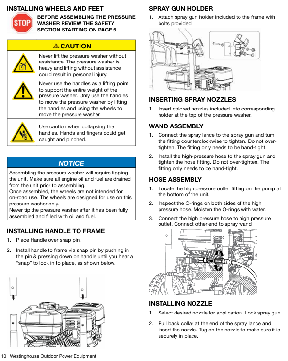
Installation of wheels and handles: Use axle pins and split pins to secure the wheels to the body bracket, and install the handles with buckles to ensure they are locked in place.
Add engine oil: Open the oil filling port on a level surface, add the recommended model of engine oil to between the "L" and "H" marks on the dipstick, and tighten the dipstick.
Add fuel: Open the fuel cap, slowly add qualified gasoline, tighten the fuel cap and clean any spilled fuel.
Connect the waterway: Connect the garden hose to the water inlet (ensure that the inlet filter is intact), open the water source, and press the trigger of the spray gun to discharge the air in the pipeline.
Install nozzle: Select the nozzle according to the cleaning requirements, pull the lance collar of the spray gun into the nozzle, release and lock it.
2. Start the process
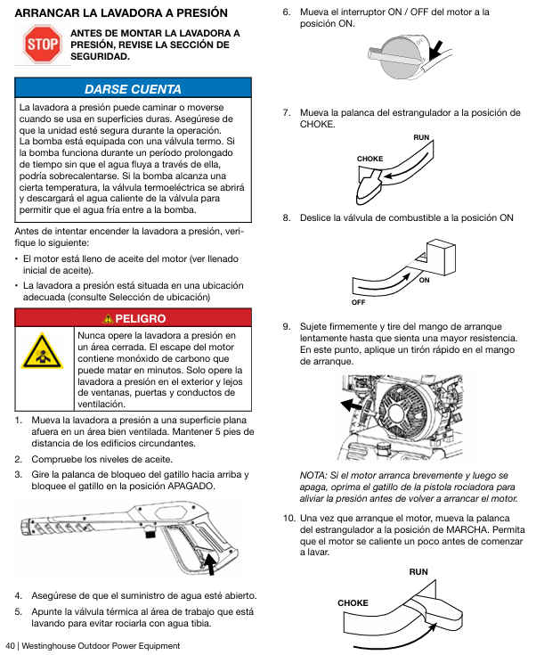
Preprocessing: Confirm that the fuel valve is open, the engine switch is set to "ON", the throttle is set to "CHOKE" (cold start), and the spray gun trigger lock is locked.
Startup operation: Hold the startup rope and slowly pull until there is resistance, then quickly pull to start; After starting the engine, gradually adjust the throttle to the "RUN" position and run it without load for 1-2 minutes to preheat.
Cleaning operation: Unlock the spray gun trigger, aim at the cleaning target, maintain a safe distance and start spraying; When soap solution is needed, replace the black nozzle, insert the siphon hose into the soap solution tank, spray soap solution to soak for 3-5 minutes, and then replace the high-pressure nozzle for flushing.
3. Shutdown process
Normal shutdown: Turn off the water source, press the trigger of the spray gun to release system pressure, turn the engine switch to "OFF", and close the fuel valve.
Emergency shutdown: In case of leakage, abnormal noise, overheating, etc., directly turn the engine switch to "OFF" to forcibly shut down.
Cleaning and organization: Disconnect all pipelines, drain the hoses and residual water in the pump body, clean the nozzle (use special tools to remove blockages), and store the spray gun and hoses.
Maintenance and Storage
1. Routine maintenance
Maintenance project cycle operation content
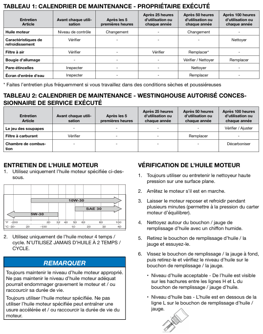
Check the oil level before each use, and if it is below the "L" mark, replenish it
Oil change for the first 5 hours/every 50 hours thereafter. After heating up, drain the oil, replace with new oil, and drain the bolt seal gasket
Check the air filter maintenance every 25 hours/replace the foam filter element every 50 hours, clean it with detergent, dry it in the air, and then apply a small amount of engine oil; The additional paper filter element of WPX3100H needs to be blown with compressed air
Spark plug maintenance: Check every 100 hours/replace annually to clean carbon deposits, check gaps, and replace damaged ones
Clean the nozzle with a specialized tool after each use to remove any blockages and ensure even spraying
Clean the spark suppressor every 50 hours by removing the muffler cover, cleaning the carbon buildup on the filter screen, and replacing it if it is damaged
Clean the inlet filter before each use, remove the inlet filter and flush impurities to avoid clogging the pump body
2. Storage requirements
Short term storage (≤ 3 months): Clean the equipment, drain the pipeline water, fill with fresh gasoline and add stabilizer, and store in a dry and ventilated place.
Long term storage (>3 months): Drain the fuel tank and carburetor, replace with new engine oil; Inject 1 tablespoon of engine oil into the cylinder and pull the starting rope several times (to prevent rust); Disconnect the spark plug wire and cover it with a dust cover.
Winter storage: After following the long-term storage process, inject RV specific antifreeze (6 ounces/177mL) into the pump body to prevent freezing and cracking.
Common troubleshooting
Possible causes and solutions for the fault phenomenon
Unable to start battery depletion (some models), insufficient/deteriorated fuel, incorrect throttle position, spark plug failure, low fuel protection triggering refueling or replacement with fresh fuel; Adjust the position of the air door; Clean or replace spark plugs; Add engine oil
Insufficient pressure/no pressure inlet flow, nozzle blockage, inlet filter blockage, high-pressure hose leakage, pump body failure increase water source flow; Clean the nozzle and inlet filter screen; Replace damaged hoses; Check the sealing components of the pump body
Unstable engine operation, clogged air filter, poor fuel supply, and air damper not adjusted to the "RUN" position. Clean or replace the air filter; Check if the fuel pipeline is blocked; Adjust the air damper to a stable operating state
The soap cannot be suctioned out, the siphon hose is blocked, the black nozzle is not used, and the soap tank level is too low. Clean the siphon hose; Replace the black nozzle; Supplement soap solution
Avoid running the pump without load for more than 5 minutes due to overheating, insufficient water intake, and malfunction of the heat release valve; Check if the water inlet is unobstructed; Contact after-sales service for maintenance of the heat release valve
- YOKOGAWA
- Reliance
- ADVANCED
- SEW
- ProSoft
- WATLOW
- Kongsberg
- FANUC
- VSD
- DCS
- PLC
- man-machine
- Covid-19
- Energy and Gender
- Energy Access
- Renewable Integration
- Energy Subsidies
- Energy and Water
- Net zero emission
- Energy Security
- Critical Minerals
- A-B
- petroleum
- Mine scale
- Sewage treatment
- cement
- architecture
- Industrial information
- New energy
- Automobile market
- electricity
- Construction site
- HIMA
- ABB
- Rockwell
- Schneider Modicon
- Siemens
- xYCOM
- Yaskawa
- Woodward
- BOSCH Rexroth
- MOOG
- General Electric
- American NI
- Rolls-Royce
- CTI
- Honeywell
- EMERSON
- MAN
- GE
- TRICONEX
- Control Wave
- ALSTOM
- AMAT
- STUDER
- KONGSBERG
- MOTOROLA
- DANAHER MOTION
- Bentley
- Galil
- EATON
- MOLEX
- Triconex
- DEIF
- B&W
- ZYGO
- Aerotech
- DANFOSS
- KOLLMORGEN
- Beijer
- Endress+Hauser
- schneider
- Foxboro
- KB
- REXROTH
- YAMAHA
- Johnson
- Westinghouse
- WAGO
- TOSHIBA
- TEKTRONIX
- BENDER
- BMCM
- SMC
- HITACHI
- HIRSCHMANN
- XP POWER
- Baldor
- Meggitt
- SHINKAWA
- Other Brands
- UniOP
- KUKA
- IBA
- Beckhoff
-
ADLINK PCI-8134 - 51-12403-0B20 PCB Board Motion Controller Card
-
ADLINK LPCI-3488A - PCI Card 51-12801-0A30 Low Profile IEEE-488 GPIB Card
-
ADLINK NUPRO-900A - industrial computer motherboard Single Board Computer
-
ADLINK cPCI-6840V - industrial control motherboard CompactPCI SBC
-
ADLINK M-342 - industrial motherboard ATX Mainboard
-
ADLINK NUPRO-935A/LV - industrial control motherboard
-
ADLINK cPCI-3538 - CompactPCI Async Serial Communications Module
-
ADLINK PCI-1610 - Card 4-Port RS-232 PCI Serial Communication Card
-
ADLINK HSL-DI32-DB-N - Distributed I/O Module 32-CH Digital Input
-
ADLINK CPCI-6860A - motherboard E7501 CompactPCI Single Board Computer
-
ADLINK PCI-8134A - 4-Axis Motion Control Card PCB Board
-
ADLINK EURESYS LINK - grabbers Video Capture Card Frame Grabber
-
ADLINK NuPRO-965DV - motherboard Industrial Control Board
-
Thermo Fisher Scientific 80100-60500 - 80000-61010R 80000-21000R 80000-60457 Spectrum System Controller ADLINK Components
-
ADLINK PCI-7296 - IO card High Density 96-CH Opto-Isolated DIO Card
-
ADLINK MXC-6322D - Matrix Industrial Computer Fanless Embedded PC
-
ADLINK DIN-825-GP4 - connector board Terminal Block Interface
-
ADLINK AMP-208C - Motion Control Card DSP-based 8-axis
-
ADLINK PCIe-GIE72 - 51-18531-0A10 2-CH GigE Vision Frame Grabber PoE+ Card
-
ADLINK PXIS-3320 - PXI/PXIe Chassis 15-slot 6U PXI/CompactPCI SEM-I-1518=9N41
-
ADLINK MI-965 - Industrial CPU Motherboard
-
ADLINK M-302 - Industrial control motherboard
-
ADLINK PCI-6308V - 51-12202-0A50 Isolated Analog Output Card PCB-I-E-1813=ZA03
-
ADLINK NUPRO-935A - Industrial Mother Board CPU Board
-
ADLINK PCI-7434 - PLOTECH Digital Output Card PCB-I-E-1182=6EX2
-
ADLINK PCI-7432 - 64 Channel Isolated Digital I/O PCI CARD
-
ADLINK NUPRO-935A/DV - 51-41802-0A10 motherboard Industrial Control Board
-
ADLINK PCIe-GIE72 - 51-18531-0A10 2-CH GigE Vision Frame Grabber PoE+ Card
-
ADLINK HSL-DI16DO16-M-NN - HSL-DI16DO16-M-NN(G)-0280 Discrete I/O Module Distributed I/O
-
ADLINK cPCI-6760D / cPCI-6840V - cPCI Single Board Computer Industrial Motherboard
-
ADLINK NuPRO-A301 - Motherboard IPC Motherboard
-
ADLINK NuPRO-935A/LV - motherboard Industrial Control Board
-
ADLINK NUPRO-E320LV - motherboard Industrial Control Board
-
ADLINK NuPRO-E42 - Industrial Control Board Motherboard
-
ADLINK M-342 - ATX Motherboard Industrial PC Mainboard
-
ADLINK CPCI-6860 / 6860A - Industrial Control Motherboard CompactPCI SBC
-
ADLINK AmITX-SL-G-Q170/GEHC(EA)-021E - 51-7A104-0A20 Industrial Motherboard w/ DDR4
-
ADLINK NUPRO-852 / NUPRO-852LV - industrial control motherboard
-
ADLINK DAQ-2006-004 - Multi-Function DAQ Cards Data Acquisition
-
ADLINK PCIe-RTV24 - Frame Grabbers Video Capture Cards PCI-e x1 4-CH 120fps
-
ADLINK PCI-8134 - 51-12403-0B20 4-Axis Motion Controller Card
-
ADLINK PCI-8132 - 2-Axis Motion Controller Card
-
ADLINK cBP-6402 - Backplane Passive Backplane
-
ADLINK cPCI-6760D - cPCI Single Board Computer Industrial Control Motherboard
-
ADLINK DIN-825-4PO(G)-0030 - Terminal Board Motion Control Breakout Board
-
ADLINK M-322 - Industrial Motherboard
-
ADLINK ABX-1301 - 51-63808-0A20 Industrial Motherboard
-
ADLINK PCI-7433 - 64-CH Isolated Digital Input Card
-
ADLINK AMP-208C - Motion Control card
-
ADLINK DIN-50S-01 - TECHNOLOGY TERMINAL BLOCK INTERFACE MODULES W/ DIN RAIL
-
ADLINK PCI-8134 - 51-12403-0B20 4-Axis Motion Controller Card
-
ADLINK MXE-201/MSSD64G - Technology Automation Computer Fanless Embedded System
-
ADLINK USB-3488A (G) - USB to GPIB CARD Controller Interface
-
ADLINK cPCI-3720L2 - SBC Single Board Computer PCB AMAT 0190-14599
-
ADLINK PCI-7251 - Relay Output Board Expansion Module
-
ADLINK PCI-8124-C - PCB Board 4-CH Encoder Trigger Card
-
ADLINK HD636 - Industrial Computer Board PCB-I-E-2200=9L32-2 Main Board
-
ADLINK USB-3488A - THERMOTRON INDUSTRIES IEEE 488 CPU INTERFACE WITH USB/GPIB
-
ADLINK MI-965 - motherboard Industrial CPU Board
-
ADLINK LPCIe-7250 - Technology Digital IO card Low Profile PCIe Relay Output
-
ADLINK NuPro-720/SCOPUS - Technology With 256MB Industrial MotherBoard
-
ADLINK NuPR0-840 - industrial control motherboard
-
ADLINK M-342 - Motherboard ATX PC Mainboard
-
ADLINK MI-965 - motherboard Industrial CPU Board
-
ADLINK CPCI-6530V/4402E/M4G - AMAT CPCI-6503VED/4402E/M4-0/SD64G-2550 Universal SBC
-
ADLINK IMB-M43-IRV - Industrial Motherboard ATX PC Board
-
ADLINK 52983 / 58183 - Chroma PXI I/O Input/Output Card + Carrier Adapter
-
ADLINK PXI-3920 - PXI 3U cPCI Industrial Controller w/ RAM SSD Embedded CPU
-
ADLINK NuPRO-842LV/P - motherboard Industrial Control PC Board
-
ADLINK PCI-7442 - 64-Channel Datalogging Acquisition Switch Card
-
ADLINK PCIe-RTV24 - Cadre Agrippeurs Vidéo de Capture Cartes Pci-E x1 4-CH
-
ADLINK ACL-7122A - TECHNOLOGY 51-11004-1A1 CIRCUIT BOARD 96-CH DIO Card
-
ADLINK PCIe-RTV24 - 51-18016-0A20 Image Acquisition Video Capture Card
-
ADLINK AMP-204C - DSP-Based 4-Axis Advanced Pulse-Train Motion Controller
-
ADLINK 52981 / 58183 - Chroma PXI Digital I/O DIO Input/Output Card + Carrier Adapter
-
ADLINK PCI-8102 - motion control card 2-Axis
-
ADLINK NuPRO-E320LV - industrial computer motherboard
-
ADLINK PCI-RTV24 - card Analog Video Capture Frame Grabber
-
ADLINK M-302 - Motherboard P/N: 08GSAQ96501102
-
ADLINK NEON-1020 - Smart camera Industrial Machine Vision
-
ADLINK AMP- 208C - card DSP-based 8-axis Motion Controller
-
ADLINK PCI-9114DG - Multi-Function Daq Card Data Acquisition
-
ADLINK MXC-6322D/BE_FanG) - Matrix PM2-MXC Fanless Embedded Computer
-
ADLINK DIN-825-4P0 - Terminal Board Motion Control Breakout Board
-
ADLINK HPCI-8S4 REV.B2 - Industrial Control Base Plate Passive Backplane
-
ADLINK HSL-DI32-DB-N - Distributed I/O Module 32-CH Digital Input
-
ADLINK NuPRO-935A/DV - industrial control motherboard
-
ADLINK PCI-7442 - Switch card 64-CH Datalogging Acquisition Card
-
ADLINK NuPRO-E42 - motherboard 51-41808-0A30 Industrial Motherboard
-
ADLINK CPCI-3610D/N45/M1G(G)-10B0 - CompactPCI Intel Atom Single Board Computer CPU Board
-
ADLINK LPCI-7250 - GP Output Isolated Digital Input Card PCB 51-12803-0A10
-
ADLINK PCI-7250 - 51-12007-0A40 PCI7250 8-CH Relay Output & 8-CH Isolated DI Card
-
ADLINK STC-1005 - 10.4inch touch panel PC E3845 CPU
-
ADLINK PCI-FIW64 - image card FireWire Frame Grabber
-
ADLINK NuPRO-935A/LV - industrial computer motherboard
-
ADLINK PCI-8164 00B0 - Centralized Motion Controller 4-axis PCB-I-E-1179=6EX2
-
ADLINK ACLD-9137F REV A1 - 51-14006-101 Screw Termination Board
-
ADLINK PCI-7248 - 51-12006-0A40 Control Card Digital I/O
-
ADLINK HPCI-8S4 - Technology Backplane PCB GaSonics 3500 Asher Passive Backplane
-
ADLINK NuPRO-E320LV - Cpu Board 51-41804-0A20 Industrial Motherboard
-
ADLINK HPX-13S4 - device baseboard Passive Backplane
-
ADLINK M-322 - industrial motherboard
-
ADLINK NuPRO-865 REV :3.0 - industrial motherboard
-
ADLINK DIN-68S-01 - Terminal Block Interface Module Cable Connection
-
ADLINK ETX-IM266-C100Z - motherboard ETX CPU Module
-
ADLINK NuPRO-E320LV - motherboard Industrial Control Board
-
ADLINK NuPRO-841 REV:2.0 - motherboard Industrial PC Board
-
ADLINK ETX-AT-N270-18 - N270 Board ASH-EAT-18/S512 ET Mainboard
-
ADLINK PCI-RTV24 - Image capture card Analog Frame Grabber
-
ADLINK PCI-8102 - card 2-Axis Motion Controller
-
ADLINK M-322 - industrial motherboard
-
ADLINK PCI-9114 REV.C2 - acquisition card Multi-Function DAQ
-
ADLINK NuPRO-865 REV :3.0 - industrial motherboard
-
ADLINK DIN-68S-01 - Terminal Block Interface Module Cable Connection
-
ADLINK M-322 - Industrial Motherboard Mainboard
-
ADLINK CPCI-6860A - E7501 dual Xeon CPCI Single Board Computer
-
ADLINK MXC-6301D(G) - Technology Expandable Fanless Embedded Computer i7-3610E
-
ADLINK NuPRO-842LV - 51-41360-0B1 Industrial Motherboard
-
ADLINK PBP-08A7 R1MO - PCB Industrial Computer Backplane Passive Backplane
-
ADLINK PCI-3488 - PCI BOARD IEEE-488 GPIB Controller Card
-
ADLINK NuPRO-935A/LV - Industrial Control Motherboard
-
ADLINK PCI-8134 - TECH 4-AXIS MOTION CONTROLLER 4209NB2039 AT23A
-
ADLINK Karbon 700-X2 - Expanded High-Performance Rugged Edge Computer Windows 10
-
ADLINK PCIe-9852 - ADcard 2-CH 8-Bit 200MS/s Digitizer Card
-
ADLINK ETX-BT-E3815 - Industrial Control Module NO AUDIO 91-71116-E020 CT66
-
ADLINK cPCI-8168-006 - cPCI NulPC Motion Control Board
-
ADLINK NuPRO-E43 - 51-41809-0A30 industrial motherboard
-
ADLINK PCI-8134A - PCB Board Motion Controller Card

K-JIANG

Add: Jimei North Road, Jimei District, Xiamen, Fujian, China
Tell:+86-15305925923