
K-WANG


Westinghouse WPro8500 and WPro12000 portable generators
Westinghouse WPro8500 and WPro12000 portable generators
Basic and Product Technical Specifications
1. Overview
This document is the official user manual for Westinghouse's two portable generators (WPro8500, WPro12000), covering the entire process from safe operation to maintenance troubleshooting, as well as product registration, after-sales support and other service information. It emphasizes the "continuous product improvement policy" and reserves the right to modify specifications. Some images may vary due to model differences.
2. Technical specification comparison
Model Running Watts Peak Watts Fuel Tank Capacity (L/G) Rated RPM Ignition Type Spark Plug Engine Displacement (cc) Stroke x Bore Oil Capacity (L) Oil Type THD
WPro8500 8500 11500 25L / 6.6G 3600 TCI F7TC 457 66×90 1.1 10W30 <5%
WPro12000 12000 15000 40L / 10.5G 3600 TCI F7TC 713 71×80 1.6 10W30 <5%
Note: Both generators do not require altitude carburetor modification. For every 300 meters (1000 feet) increase in altitude, the engine horsepower decreases by approximately 3.5% (the decrease is more significant without carburetor modification). For altitude kits, please contact the service team.
Safety warnings and regulatory requirements
1. Core security warning
California Proposition 65 Warning: ① Engine exhaust contains chemicals known to cause cancer, birth defects, or reproductive harm; ② Some components of the product and related accessories contain harmful chemicals of the same type, and hand washing is required after operation.
DANGER level risk:
Do not use in damp/rainy/snowy environments to avoid short circuits or malfunctions;
It is prohibited to operate in a confined space. The exhaust contains carbon monoxide (colorless, odorless, and toxic), and can only be used outdoors and away from doors, windows, and ventilation openings.
Warning level risk:
Electric shock risk: A certified electrician is required to connect to the power grid, use grounding extension cords, and avoid touching live terminals/operating with wet hands;
Gasoline risks: refuel in outdoor ventilated areas, refuel after cooling down, do not overfill (leave room for expansion), stay away from fire sources;
Equipment abnormality: It is prohibited to operate when the load overheats/output drops/sparks/smoke occur, and it is also prohibited to supply power to medical equipment.
2. Definition of Security Terms
Meaning of Terms
DANGER's failure to avoid may result in death or serious injury
Warning: Failure to avoid may result in death or serious injury
CAUTION may cause minor/moderate injuries if not avoided
NOTICE may cause equipment/property damage or abnormal operation
NOTE: Necessary operations/conditions to ensure the normal operation of equipment
Unpacking and assembly process
1. Open box contents
Model includes items
WPro8500 ① User Manual; ② Quick Start Guide/Maintenance Plan; ③ Lift bracket (1 piece); ④ Wireless remote control (1 unit); ⑤ 1.1L SAE 10W30 engine oil (1 bottle); ⑥ Spark plug socket wrench (1 piece); ⑦ Wheel kit accessory box; ⑧ Funnel (1 piece)
WPro12000 ① User Manual; ② Quick Start Guide/Maintenance Plan; ③ Wireless remote control (1 unit); ④ 1.6L SAE 10W30 engine oil (1 bottle); ⑤ Spark plug socket wrench (1 piece); ⑥ Wheel kit accessory box; ⑦ Funnel (1 piece)
Wheel kit accessory box: 2 washers, 4 M8 × 16mm flange bolts, 2 split pins, 2 wheel axle pins.
2. Assembly steps
Wheel and foot installation:
Place the generator on a horizontal surface, elevate the rear with wooden blocks, and install the support feet with M8 flange bolts;
The axle pin passes through the washer and the wheel, and is installed through the frame axle bracket. The split pin is fixed, and the other side of the wheel is operated repeatedly;
Attention: Before assembly, the engine oil and fuel must be drained. The wheel kit is only applicable to this generator and is not allowed for road use.
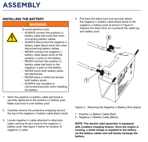
Battery installation (key steps for preventing electric shock):
Confirm that the positive (red) cable is securely fastened to the positive pole of the battery and covered with a protective cover;
Remove the protective packaging of the negative (black) cable terminal, disconnect the cable tie and lead it to the negative pole;
Open the black sleeve, tighten the negative cable, and then put back the protective sleeve;
Rule: Connect the power first and then the negative, disconnect the power first and then the negative, prohibit metal tools from crossing the two poles, and use insulated tools for operation.
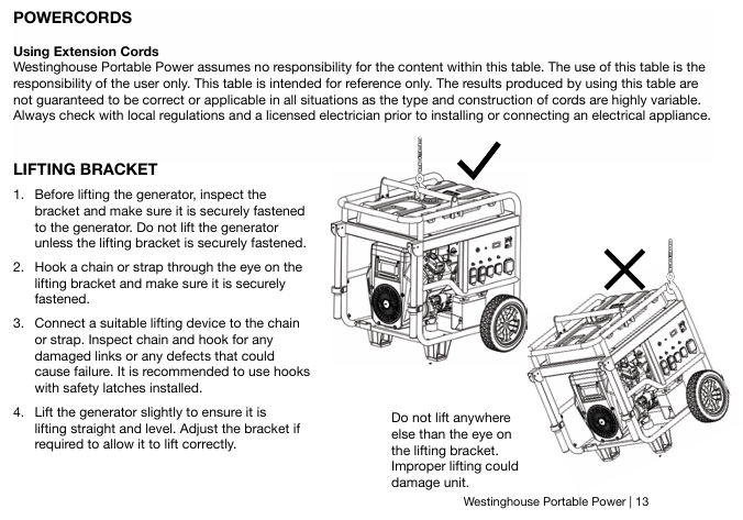
Installation of lifting bracket (WPro8500 only): Align the bracket on the top of the fuel tank and fix it with 4 M8 flange bolts.
Operation Guide
1. Preparation before startup
Location selection: Outdoor ventilation, level and solid surface, at least 6 feet (1.8 meters) away from buildings/combustibles, away from doors, windows/ventilation openings.
Environmental requirements: Do not operate on rainy/snowy days, operate on dry surfaces to avoid loose materials (sand/grass debris) blocking the air vents.
Load and grounding: Disconnect all loads (unplug extension wires) before starting; A certified electrician is required to determine whether a grounding rod is needed (usually required when connecting the backup power supply to the transfer switch), and connect the control panel grounding terminal with a ≥ 10 AWG copper wire for grounding.
2. Fuel and oil requirements
Fuel: Only use unleaded gasoline, ethanol content ≤ 10%, octane rating ≥ 87; Stop the machine for cooling before refueling, ensure that the oil level does not exceed the neck of the filling port, and check for leaks after refueling.
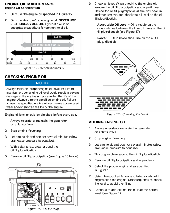
Engine oil: The new engine has no engine oil, and 10W30 engine oil must be added before the first start-up (5W30 in winter and SAE30 in summer); Check the liquid level of the refrigeration unit, which should be between the H (high) and L (low) marks on the dipstick.
3. Startup method
Startup method, operating steps, applicable models, precautions
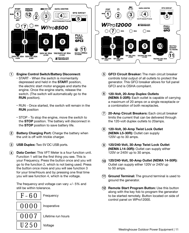
Electric start 1. Confirm that the engine oil is sufficient and the battery is connected; 2. Reset the circuit breaker; 3. Turn the fuel valve to ON; 4. Press the switch to START and release it after starting (automatic return to RUN). Both options are applicable. If it does not start for 5 seconds, release it and retry after 15 seconds; Charging when the battery is depleted
Backlash start 1. Same as 1-3 above; 2. Slowly pull the rope until the resistance increases, and quickly pull it upwards away from the generator. When only the WPro8500 battery runs out of power/disconnects, manually turn on the choke and turn it off after starting
Remote start 1. Turn the switch to RUN; 2. Long press the REMOTE PAIRING button on the panel for 3 seconds; 3. Long press the STOP button on the remote control until the indicator light flashes, and then long press the START button until it flashes; 4. Press and hold the PAIRING key for 3 seconds to complete pairing; 5. Press the START button on the remote control to start both models, with an effective distance of ≤ 100 feet (affected by battery level). After starting, there will be a 15 second delay in output
4. Stop method
Normal stop: 1 Disconnect all loads; 2. Cooling during no-load operation; 3. Turn the switch to OFF; 4. Close the fuel valve (allow the carburetor to run out of fuel during long-term storage).
Emergency stop: Simply turn the engine control switch to OFF.
Special maintenance operation
Oil change: When the engine is in a cold state, drain the oil from the oil pan through the oil drain plug, remove the plug and drain, then reinstall and add oil to the standard level.
Air filter cleaning: Remove the cover and take out the filter cotton, clean with household detergent and warm water, squeeze and drain (do not twist), air dry, apply a thin layer of cleaning oil, and reinstall according to the "fine filter (ash) inside, coarse filter (black) outside".
Spark plug maintenance: Remove the spark plug with a spark socket wrench, check the insulation layer for cracks and a gap of 0.027-0.032 inches (0.60-0.80mm), clean and reinstall it; Recommended replacement models: AC Delco 4EXLS, Autolite 52, Champion N9YC, Bosch W7DC, Torch F7TC.
Battery maintenance: Start the generator every 2-3 months and charge it for 15 minutes, or connect the charger to the charging port (RUN mode) for charging; The replacement model is as follows:
Model Westinghouse Part Number Compatible Battery Model Voltage (V) Capacity (Ah) Size (inches)
WPro8500 100557 YT9A 12 9 5 5/16 × 3 × 5 3/8
WPro12000 100639 YT51913-22 12 20 7 1/8 × 3 × 6 9/16
Troubleshooting
Possible causes and solutions for the problem
The engine is running but there is no power output. 1. The circuit breaker has tripped; 2. The power plug is not securely plugged in; 3. Power cord malfunction; 4. Electrical equipment malfunction; 5. GFCI trips; 6. Internal equipment malfunction: 1. Reset the circuit breaker and check for overload; 2. Re plug (the 240V plug needs to be turned clockwise by 1/4 turn); 3. Replace the power cord; 4. Connect to normal equipment testing; 5. Reset the GFCI circuit breaker; 6. Send to authorized service points
The engine cannot start/stalls after starting. 1. The fuel valve is closed; 2. Lack of gasoline; 3. Fuel pipeline blockage; 4. The startup battery runs out of power; 5. The air filter is dirty; 6. Low oil level (low oil protection); 7. Spark plug not tightened/faulty; 8. Fuel deterioration: 1. Open the fuel valve; 2. Add gasoline that meets the requirements; 3. Check and clean the fuel passage; 4. Charging (electric start only); 5. Clean/replace the air filter; 6. Add engine oil to the standard level; 7. Tighten/replace spark plugs; 8. Drain the deteriorated fuel and add new fuel
Remote start failure: 1. The remote control battery is dead; 2. Exceeding the remote control distance (>100 feet); 3. The remote control is not paired with the generator. 1. Replace the remote control battery; 2. Close to the generator (≤ 100 feet); 3. Follow the pairing process again
Sudden shutdown of generator: 1. Lack of fuel; 2. Low oil level (protective shutdown); 3. Excessive load; 4. Internal equipment malfunction: 1. Add gasoline; 2. Add engine oil; 3. Reduce load after restart; 4. Send to authorized service points
Product drawings
Explosion view: WPro8500 (page 26), WPro12000 (page 31) complete machine parts breakdown, including part numbers and names (such as generator assembly, fuel tank, control panel, etc.).
Engine view: Position markings and part numbers for the internal structures (pistons, connecting rods, valves, ignition coils, etc.) of two engine models.
Schematic diagram: Schematic diagram of electrical system (voltage regulator, wiring harness), fuel system (carbon canister, oil pipe) and other connections.
- YOKOGAWA
- Reliance
- ADVANCED
- SEW
- ProSoft
- WATLOW
- Kongsberg
- FANUC
- VSD
- DCS
- PLC
- man-machine
- Covid-19
- Energy and Gender
- Energy Access
- Renewable Integration
- Energy Subsidies
- Energy and Water
- Net zero emission
- Energy Security
- Critical Minerals
- A-B
- petroleum
- Mine scale
- Sewage treatment
- cement
- architecture
- Industrial information
- New energy
- Automobile market
- electricity
- Construction site
- HIMA
- ABB
- Rockwell
- Schneider Modicon
- Siemens
- xYCOM
- Yaskawa
- Woodward
- BOSCH Rexroth
- MOOG
- General Electric
- American NI
- Rolls-Royce
- CTI
- Honeywell
- EMERSON
- MAN
- GE
- TRICONEX
- Control Wave
- ALSTOM
- AMAT
- STUDER
- KONGSBERG
- MOTOROLA
- DANAHER MOTION
- Bentley
- Galil
- EATON
- MOLEX
- Triconex
- DEIF
- B&W
- ZYGO
- Aerotech
- DANFOSS
- KOLLMORGEN
- Beijer
- Endress+Hauser
- schneider
- Foxboro
- KB
- REXROTH
- YAMAHA
- Johnson
- Westinghouse
- WAGO
- TOSHIBA
- TEKTRONIX
- BENDER
- BMCM
- SMC
- HITACHI
- HIRSCHMANN
- XP POWER
- Baldor
- Meggitt
- SHINKAWA
- Other Brands
- UniOP
- KUKA
- IBA
- Beckhoff
-
ADLINK PCI-8134 - 51-12403-0B20 PCB Board Motion Controller Card
-
ADLINK LPCI-3488A - PCI Card 51-12801-0A30 Low Profile IEEE-488 GPIB Card
-
ADLINK NUPRO-900A - industrial computer motherboard Single Board Computer
-
ADLINK cPCI-6840V - industrial control motherboard CompactPCI SBC
-
ADLINK M-342 - industrial motherboard ATX Mainboard
-
ADLINK NUPRO-935A/LV - industrial control motherboard
-
ADLINK cPCI-3538 - CompactPCI Async Serial Communications Module
-
ADLINK PCI-1610 - Card 4-Port RS-232 PCI Serial Communication Card
-
ADLINK HSL-DI32-DB-N - Distributed I/O Module 32-CH Digital Input
-
ADLINK CPCI-6860A - motherboard E7501 CompactPCI Single Board Computer
-
ADLINK PCI-8134A - 4-Axis Motion Control Card PCB Board
-
ADLINK EURESYS LINK - grabbers Video Capture Card Frame Grabber
-
ADLINK NuPRO-965DV - motherboard Industrial Control Board
-
Thermo Fisher Scientific 80100-60500 - 80000-61010R 80000-21000R 80000-60457 Spectrum System Controller ADLINK Components
-
ADLINK PCI-7296 - IO card High Density 96-CH Opto-Isolated DIO Card
-
ADLINK MXC-6322D - Matrix Industrial Computer Fanless Embedded PC
-
ADLINK DIN-825-GP4 - connector board Terminal Block Interface
-
ADLINK AMP-208C - Motion Control Card DSP-based 8-axis
-
ADLINK PCIe-GIE72 - 51-18531-0A10 2-CH GigE Vision Frame Grabber PoE+ Card
-
ADLINK PXIS-3320 - PXI/PXIe Chassis 15-slot 6U PXI/CompactPCI SEM-I-1518=9N41
-
ADLINK MI-965 - Industrial CPU Motherboard
-
ADLINK M-302 - Industrial control motherboard
-
ADLINK PCI-6308V - 51-12202-0A50 Isolated Analog Output Card PCB-I-E-1813=ZA03
-
ADLINK NUPRO-935A - Industrial Mother Board CPU Board
-
ADLINK PCI-7434 - PLOTECH Digital Output Card PCB-I-E-1182=6EX2
-
ADLINK PCI-7432 - 64 Channel Isolated Digital I/O PCI CARD
-
ADLINK NUPRO-935A/DV - 51-41802-0A10 motherboard Industrial Control Board
-
ADLINK PCIe-GIE72 - 51-18531-0A10 2-CH GigE Vision Frame Grabber PoE+ Card
-
ADLINK HSL-DI16DO16-M-NN - HSL-DI16DO16-M-NN(G)-0280 Discrete I/O Module Distributed I/O
-
ADLINK cPCI-6760D / cPCI-6840V - cPCI Single Board Computer Industrial Motherboard
-
ADLINK NuPRO-A301 - Motherboard IPC Motherboard
-
ADLINK NuPRO-935A/LV - motherboard Industrial Control Board
-
ADLINK NUPRO-E320LV - motherboard Industrial Control Board
-
ADLINK NuPRO-E42 - Industrial Control Board Motherboard
-
ADLINK M-342 - ATX Motherboard Industrial PC Mainboard
-
ADLINK CPCI-6860 / 6860A - Industrial Control Motherboard CompactPCI SBC
-
ADLINK AmITX-SL-G-Q170/GEHC(EA)-021E - 51-7A104-0A20 Industrial Motherboard w/ DDR4
-
ADLINK NUPRO-852 / NUPRO-852LV - industrial control motherboard
-
ADLINK DAQ-2006-004 - Multi-Function DAQ Cards Data Acquisition
-
ADLINK PCIe-RTV24 - Frame Grabbers Video Capture Cards PCI-e x1 4-CH 120fps
-
ADLINK PCI-8134 - 51-12403-0B20 4-Axis Motion Controller Card
-
ADLINK PCI-8132 - 2-Axis Motion Controller Card
-
ADLINK cBP-6402 - Backplane Passive Backplane
-
ADLINK cPCI-6760D - cPCI Single Board Computer Industrial Control Motherboard
-
ADLINK DIN-825-4PO(G)-0030 - Terminal Board Motion Control Breakout Board
-
ADLINK M-322 - Industrial Motherboard
-
ADLINK ABX-1301 - 51-63808-0A20 Industrial Motherboard
-
ADLINK PCI-7433 - 64-CH Isolated Digital Input Card
-
ADLINK AMP-208C - Motion Control card
-
ADLINK DIN-50S-01 - TECHNOLOGY TERMINAL BLOCK INTERFACE MODULES W/ DIN RAIL
-
ADLINK PCI-8134 - 51-12403-0B20 4-Axis Motion Controller Card
-
ADLINK MXE-201/MSSD64G - Technology Automation Computer Fanless Embedded System
-
ADLINK USB-3488A (G) - USB to GPIB CARD Controller Interface
-
ADLINK cPCI-3720L2 - SBC Single Board Computer PCB AMAT 0190-14599
-
ADLINK PCI-7251 - Relay Output Board Expansion Module
-
ADLINK PCI-8124-C - PCB Board 4-CH Encoder Trigger Card
-
ADLINK HD636 - Industrial Computer Board PCB-I-E-2200=9L32-2 Main Board
-
ADLINK USB-3488A - THERMOTRON INDUSTRIES IEEE 488 CPU INTERFACE WITH USB/GPIB
-
ADLINK MI-965 - motherboard Industrial CPU Board
-
ADLINK LPCIe-7250 - Technology Digital IO card Low Profile PCIe Relay Output
-
ADLINK NuPro-720/SCOPUS - Technology With 256MB Industrial MotherBoard
-
ADLINK NuPR0-840 - industrial control motherboard
-
ADLINK M-342 - Motherboard ATX PC Mainboard
-
ADLINK MI-965 - motherboard Industrial CPU Board
-
ADLINK CPCI-6530V/4402E/M4G - AMAT CPCI-6503VED/4402E/M4-0/SD64G-2550 Universal SBC
-
ADLINK IMB-M43-IRV - Industrial Motherboard ATX PC Board
-
ADLINK 52983 / 58183 - Chroma PXI I/O Input/Output Card + Carrier Adapter
-
ADLINK PXI-3920 - PXI 3U cPCI Industrial Controller w/ RAM SSD Embedded CPU
-
ADLINK NuPRO-842LV/P - motherboard Industrial Control PC Board
-
ADLINK PCI-7442 - 64-Channel Datalogging Acquisition Switch Card
-
ADLINK PCIe-RTV24 - Cadre Agrippeurs Vidéo de Capture Cartes Pci-E x1 4-CH
-
ADLINK ACL-7122A - TECHNOLOGY 51-11004-1A1 CIRCUIT BOARD 96-CH DIO Card
-
ADLINK PCIe-RTV24 - 51-18016-0A20 Image Acquisition Video Capture Card
-
ADLINK AMP-204C - DSP-Based 4-Axis Advanced Pulse-Train Motion Controller
-
ADLINK 52981 / 58183 - Chroma PXI Digital I/O DIO Input/Output Card + Carrier Adapter
-
ADLINK PCI-8102 - motion control card 2-Axis
-
ADLINK NuPRO-E320LV - industrial computer motherboard
-
ADLINK PCI-RTV24 - card Analog Video Capture Frame Grabber
-
ADLINK M-302 - Motherboard P/N: 08GSAQ96501102
-
ADLINK NEON-1020 - Smart camera Industrial Machine Vision
-
ADLINK AMP- 208C - card DSP-based 8-axis Motion Controller
-
ADLINK PCI-9114DG - Multi-Function Daq Card Data Acquisition
-
ADLINK MXC-6322D/BE_FanG) - Matrix PM2-MXC Fanless Embedded Computer
-
ADLINK DIN-825-4P0 - Terminal Board Motion Control Breakout Board
-
ADLINK HPCI-8S4 REV.B2 - Industrial Control Base Plate Passive Backplane
-
ADLINK HSL-DI32-DB-N - Distributed I/O Module 32-CH Digital Input
-
ADLINK NuPRO-935A/DV - industrial control motherboard
-
ADLINK PCI-7442 - Switch card 64-CH Datalogging Acquisition Card
-
ADLINK NuPRO-E42 - motherboard 51-41808-0A30 Industrial Motherboard
-
ADLINK CPCI-3610D/N45/M1G(G)-10B0 - CompactPCI Intel Atom Single Board Computer CPU Board
-
ADLINK LPCI-7250 - GP Output Isolated Digital Input Card PCB 51-12803-0A10
-
ADLINK PCI-7250 - 51-12007-0A40 PCI7250 8-CH Relay Output & 8-CH Isolated DI Card
-
ADLINK STC-1005 - 10.4inch touch panel PC E3845 CPU
-
ADLINK PCI-FIW64 - image card FireWire Frame Grabber
-
ADLINK NuPRO-935A/LV - industrial computer motherboard
-
ADLINK PCI-8164 00B0 - Centralized Motion Controller 4-axis PCB-I-E-1179=6EX2
-
ADLINK ACLD-9137F REV A1 - 51-14006-101 Screw Termination Board
-
ADLINK PCI-7248 - 51-12006-0A40 Control Card Digital I/O
-
ADLINK HPCI-8S4 - Technology Backplane PCB GaSonics 3500 Asher Passive Backplane
-
ADLINK NuPRO-E320LV - Cpu Board 51-41804-0A20 Industrial Motherboard
-
ADLINK HPX-13S4 - device baseboard Passive Backplane
-
ADLINK M-322 - industrial motherboard
-
ADLINK NuPRO-865 REV :3.0 - industrial motherboard
-
ADLINK DIN-68S-01 - Terminal Block Interface Module Cable Connection
-
ADLINK ETX-IM266-C100Z - motherboard ETX CPU Module
-
ADLINK NuPRO-E320LV - motherboard Industrial Control Board
-
ADLINK NuPRO-841 REV:2.0 - motherboard Industrial PC Board
-
ADLINK ETX-AT-N270-18 - N270 Board ASH-EAT-18/S512 ET Mainboard
-
ADLINK PCI-RTV24 - Image capture card Analog Frame Grabber
-
ADLINK PCI-8102 - card 2-Axis Motion Controller
-
ADLINK M-322 - industrial motherboard
-
ADLINK PCI-9114 REV.C2 - acquisition card Multi-Function DAQ
-
ADLINK NuPRO-865 REV :3.0 - industrial motherboard
-
ADLINK DIN-68S-01 - Terminal Block Interface Module Cable Connection
-
ADLINK M-322 - Industrial Motherboard Mainboard
-
ADLINK CPCI-6860A - E7501 dual Xeon CPCI Single Board Computer
-
ADLINK MXC-6301D(G) - Technology Expandable Fanless Embedded Computer i7-3610E
-
ADLINK NuPRO-842LV - 51-41360-0B1 Industrial Motherboard
-
ADLINK PBP-08A7 R1MO - PCB Industrial Computer Backplane Passive Backplane
-
ADLINK PCI-3488 - PCI BOARD IEEE-488 GPIB Controller Card
-
ADLINK NuPRO-935A/LV - Industrial Control Motherboard
-
ADLINK PCI-8134 - TECH 4-AXIS MOTION CONTROLLER 4209NB2039 AT23A
-
ADLINK Karbon 700-X2 - Expanded High-Performance Rugged Edge Computer Windows 10
-
ADLINK PCIe-9852 - ADcard 2-CH 8-Bit 200MS/s Digitizer Card
-
ADLINK ETX-BT-E3815 - Industrial Control Module NO AUDIO 91-71116-E020 CT66
-
ADLINK cPCI-8168-006 - cPCI NulPC Motion Control Board
-
ADLINK NuPRO-E43 - 51-41809-0A30 industrial motherboard
-
ADLINK PCI-8134A - PCB Board Motion Controller Card

K-JIANG

Add: Jimei North Road, Jimei District, Xiamen, Fujian, China
Tell:+86-15305925923