
K-WANG


Yokogawa WTB10-DO Series Dissolved Oxygen Measurement System Terminal Box
Yokogawa WTB10-DO Series Dissolved Oxygen Measurement System Terminal Box
Product basic information and positioning
1. Core functions and application scenarios
Product positioning: The WTB10-DO series terminal box is a supporting equipment for dissolved oxygen measurement systems, used for signal conversion when dissolved oxygen sensors and converters (such as FLXA402, FLXA202, FLXA21) are installed separately. It supports outdoor installation (in accordance with JIS C0920 rainproof structure standard).
System association: It needs to be used in conjunction with specific models of dissolved oxygen sensors (such as DO30G), converters, and installation brackets (such as PH8HG, PB350G, DOX8HS) from Yokogawa. Different models of terminal boxes correspond to different converters. The specific association manual is shown in the table below:
Associated device model, device name, corresponding manual number
FLXA402 4-wire converter IM 12A01F05-01eN
FLXA202, FLXA21 2-wire liquid analyzer IM 12A01A02-01E
DO30G dissolved oxygen sensor IM 12J5B3-01E
PH8HG guide bracket IM 12B7M2-01E
PB350G floating bracket IM 19H1E1-01E
DOX8HS diving bracket IM 19H1D2-01E
Product specifications and model description
1. Core specification parameters
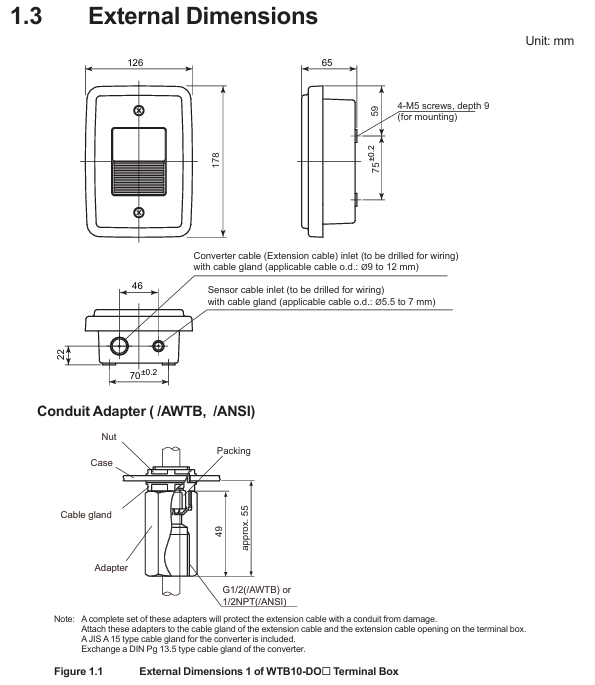
Structural type: Outdoor type, JIS C0920 rainproof structure
Shell material: Glass fiber reinforced polycarbonate resin
Shell color gray green (Munsell color card 2.5 GY 5.0/1.0 or equivalent color)
Installation methods: bracket installation (no additional bracket required), pipeline installation (requires/P option bracket), wall installation (requires/W option bracket)
Weight: Terminal box body 0.5kg; Pipe installation bracket about 0.7kg; Wall installation bracket about 0.3kg
Working temperature -10~50 ℃
Cable entrance sensor cable: diameter 13mm, equipped with JIS A8 grade cable sealing sleeve (suitable for cable outer diameter 5.5-7mm); Special extension cable: diameter 21mm, equipped with JIS A15 grade cable sealing sleeve (suitable for cable outer diameter 9-12mm)
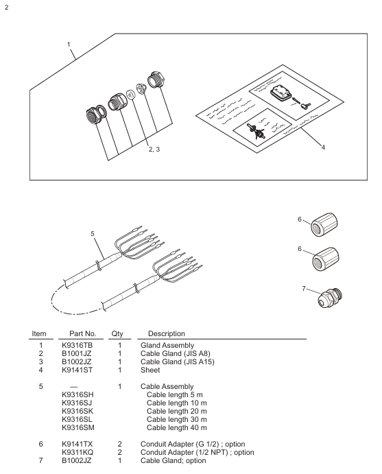
The length of the dedicated extension cable can be selected from 5m, 10m, 20m, 30m, and 40m, and the end has been pre treated; When installing/AWTB (G1/2 internal thread) or/ANSI (1/2 NPT) conduit adapters, a sealing sleeve and adapter will be included
2. Model and suffix code rules
Model structure: WTB10- [Applicable system code] - [Fixed suffix] - [Cable length code]+[Option code], the meanings of each part are as follows:
Meaning of Component Code Examples
Applicable System - DO3 compatible with FLXA402, FLXA202, FLXA21 (pin terminal, cable with pin terminal)
-DO4 compatible with FLXA202, FLXA21 (M4 threaded terminal, with M4 ring terminal cable)
-DO5 compatible with FLXA402 (M3 threaded terminal, with M3 ring terminal cable)
Fixed suffix - NN is used for all models
Cable length -00 without extension cable
-05/-10/-20/-30/-40 Extension cable length 5m/10m/20m/30m/40m
Option code/P includes pipeline installation bracket
/W includes wall installation bracket
/AWTB includes G1/2 internal thread conduit adapter
/ANSI includes 1/2 NPT conduit adapter
Accessories List: Different models of terminal boxes come with different standard accessories. Taking WTB10-DO3 as an example, the standard accessories include sensor cable sealing sleeve (B1001JZ), extension cable sealing sleeve (B1002JZ), and corresponding length extension cable (K9316S □ series). Corresponding brackets are included when installing/P or/W, and conduit adapters are included when installing/AWTB or/ANSI.
Installation process and requirements
1. Preparation before installation
Installation environment:
Outdoor rainproof, sensors should be installed as close as possible to the terminal box;
Avoid high humidity and corrosive gas environments (to prevent contact failures caused by cable breakage, poor insulation, or corrosion);
The terminal box cover is equipped with a silicone desiccant (about 30g), and its moisture absorption status needs to be checked regularly.
Installation tools and accessories: Prepare M5 screws (bracket installation, length=bracket thickness+5mm), M8 screws (wall installation, 3 pieces), U-bolts (pipeline installation, suitable for pipes with an outer diameter of 60.5mm), as well as standard accessories such as cable glands and extension cables according to the installation method.
2. Detailed explanation of installation method
(1) Bracket installation
Drill holes on the bracket according to the installation hole size of the terminal box (4 holes with a diameter of 5.5mm, hole spacing of 75 ± 0.2mm × 70 ± 0.2mm);
Fix the terminal box on the bracket with 4 M5 screws, and the screw depth should cover the thickness of the bracket before penetrating 5mm to ensure firmness.
(2) Pipeline installation (requires/P option support)
Fix the pipeline installation bracket (K9141SA) onto a sturdy pipeline with an outer diameter of 60.5mm (nominal 50A) using U-bolts, washers, and nuts;
Fix the terminal box on the bracket with 4 M5 screws, which can be installed vertically or horizontally.
(3) Wall installation (requires/W option bracket)
Drill holes on the wall according to the size (3 M8 screw holes, with a hole spacing that meets the positioning requirements of the terminal box center);
Fix the wall mounting bracket (K9141SC) to the wall with 3 M8 screws, and then secure the terminal box to the bracket with 4 M5 screws.
3. Cable entrance opening
The cable entrance at the bottom of the terminal box is a pre designed groove (not opened), which needs to be opened with a tool before wiring: align the tip of a cross screwdriver or other tool with the center of the groove, lightly tap the tool head with a hammer, and break the entrance hole along the groove (the sensor cable entrance and the extension cable entrance need to be opened separately).

Wiring operation specifications
1. Sensor cable connection
Dismantling the terminal box cover: Loosen the 2 screws on the front panel and remove the cover;
Installation of cable sealing sleeve: Remove the nut of JIS A8 grade cable sealing sleeve (B1001JZ) and assemble it to the sensor cable inlet in the order of "nut → gasket → main body → cap", ensuring that the sealing sleeve is in contact with the box body;
Cable insertion: Remove the cap, clamping claw, and rubber gasket from the sealing sleeve, place it on the sensor cable, and insert the front end of the cable into the terminal box;
Wiring: Connect the sensor cable core wires according to the terminal numbers (refer to the correspondence between "core wire color terminal number": brown -16, white -12, black -11, green -14, yellow -15, red -13), ensuring correct and secure wiring;
Sealing fixation: Install the rubber gasket and clamping claw back into the sealing sleeve, tighten the cap to prevent water ingress, and be careful not to overtighten and damage the cable.
2. Extend cable connection (terminal box converter)
Preparation work: The two ends of the extension cable have been pre treated (with no directional difference). If conduit protection is required, the DIN Pg13.5 sealing sleeve at the inlet of the converter sensor cable needs to be replaced with a JIS A15 level sealing sleeve (standard);
Install sealing sleeve/adapter:
No conduit: Install the JIS A15 grade sealing sleeve (B1002JZ) onto the extension cable in the order of "cap → clamping claw → rubber gasket → main body → gasket → nut", and fix the nut after the cable enters the terminal box;
With conduit: Replace the cap of the sealing sleeve with the optional/AWTB (G1/2) or/ANSI (1/2 NPT) adapter, tighten the adapter, and connect the conduit union;
Wiring: Connect the extension cable core wires according to the terminal numbers to ensure consistency with the terminal correspondence of the sensor cable;
Cover the box: After checking the wiring is correct, install the front panel cover back into the terminal box and tighten the screws to ensure sealing.
3. Wiring diagram
WTB10-DO3/- DO4 terminal box: The sensor cable and extension cable are connected to terminals 11 (T1, black), 12 (T2, white), 13 (IE, red), 14 (S, green), 15 (RE, yellow), 16 (SE, brown). The converter (FLXA402/FLXA202/FLXA21) receives signals through the extension cable;
WTB10-DO5 terminal box: only compatible with FLXA402 converter, wiring logic is consistent with - DO3/- DO4, please note that the terminal thread specification is M3 (- DO3 is pin type, - DO4 is M4).
Inspection and maintenance
1. Regular inspection (recommended once a year or every two years, with early inspection in case of abnormalities)
**Moisture inspection * *: Remove the terminal box cover and check if the interior is damp. If it is damp, use a hair dryer to dry it; Several desiccants (silica gel) are saturated with moisture, replace with spare desiccants (30g/part, part number K9020XR);
Corrosion inspection: Check whether the terminals and wires have corroded due to the invasion of corrosive gases. If there is a risk of poor contact or wire breakage, the corroded parts need to be replaced; When replacing the core wire crimping terminal, it is necessary to keep the wiring number label (ribbon) to avoid wiring errors.
2. Maintain parts list
The commonly used maintenance parts for terminal boxes include seals, fasteners, desiccants, etc. Different models correspond to slightly different part numbers. Taking WTB10-DO3 as an example:
Part name, part number, quantity, and purpose
O-ring G9303NB 2 sealing box gap
Desiccant (30g) K9020XR 1 absorbs moisture inside the box
Panel screws (M3 × 4) Y9304LB 2 fix the front panel
Install screws (M5 × 8) Y9508JU 4 to fix the terminal box and bracket
Cable sealing sleeve (JIS A8) B1001JZ 1 sensor cable sealing
Cable sealing sleeve (JIS A15) B1002JZ 1 extension cable sealing
Key precautions
Installation sealing: All cable entrances and box covers must be sealed to prevent rainwater and moisture from entering; When adapting the conduit, the flexible joint should be tightened to avoid cable protection failure;
Wiring specifications: strictly follow the corresponding wiring of "core wire color terminal number", incorrect wiring may cause measurement abnormalities or equipment damage; The length of the extended cable must be consistent with the selection and cannot be cut or spliced arbitrarily;
Environmental protection: Although it is an outdoor type, it is still necessary to avoid long-term exposure to strong corrosion and high humidity environments, and regularly check the condition of desiccants and seals;
Parts replacement: Only spare parts certified by Yokogawa (such as sealing sleeves, brackets, desiccants) can be used. Non certified parts may affect equipment performance and safety.
- YOKOGAWA
- Reliance
- ADVANCED
- SEW
- ProSoft
- WATLOW
- Kongsberg
- FANUC
- VSD
- DCS
- PLC
- man-machine
- Covid-19
- Energy and Gender
- Energy Access
- Renewable Integration
- Energy Subsidies
- Energy and Water
- Net zero emission
- Energy Security
- Critical Minerals
- A-B
- petroleum
- Mine scale
- Sewage treatment
- cement
- architecture
- Industrial information
- New energy
- Automobile market
- electricity
- Construction site
- HIMA
- ABB
- Rockwell
- Schneider Modicon
- Siemens
- xYCOM
- Yaskawa
- Woodward
- BOSCH Rexroth
- MOOG
- General Electric
- American NI
- Rolls-Royce
- CTI
- Honeywell
- EMERSON
- MAN
- GE
- TRICONEX
- Control Wave
- ALSTOM
- AMAT
- STUDER
- KONGSBERG
- MOTOROLA
- DANAHER MOTION
- Bentley
- Galil
- EATON
- MOLEX
- Triconex
- DEIF
- B&W
- ZYGO
- Aerotech
- DANFOSS
- KOLLMORGEN
- Beijer
- Endress+Hauser
- schneider
- Foxboro
- KB
- REXROTH
- YAMAHA
- Johnson
- Westinghouse
- WAGO
- TOSHIBA
- TEKTRONIX
- BENDER
- BMCM
- SMC
- HITACHI
- HIRSCHMANN
- XP POWER
- Baldor
- Meggitt
- SHINKAWA
- Other Brands
- UniOP
- KUKA
- IBA
- Beckhoff
-
LTI SC52.0040.0012.0000.0 - Servo Drive
-
Lti SC52.0040.0012.0000.0 - Servo Drive
-
Milton Industries LTI Tool By Milton LT1240 - 1/2" Drive Lugnut Remover
-
LTi Drives SO84.200.P030.0000.0-W - Servo Spindle Drive
-
LTI DRIVES LSP08-035-320-30-B0R1PY170 - Servo Motor
-
LTI DRIVES SE84.200.SC00.0001.0-W - Servo Drive
-
Lust CDE34.005.W2.2 - Lti Drives Controller
-
LTi SO84.012.0030.0011.2 - ServoOne Servo Drive
-
LTi Drives SO CM-P.0010.11.00.0 - Servo Drive Controller
-
LTi CDE34.017.W3.0 - Servo Drive
-
LTI Drives CDB32.004, C2.0,SH - Positioning Controller
-
LUST CM-CAN1 - LTi DRIVES Communication Module
-
LTi SO84.012.1030.0000.2 - Servo Drive
-
LTI MOOG CDE54.044 - PITCHMASTER FREQUENCY CONVERTER 181-01019
-
MOOG LTI 181-01019 CDE54.044 - PITCHMASTER FREQUENCY CONVERTER
-
Lust LTi Drives CDE34.010,D2.0 - Servo Drive Controller
-
LTI SO84.032.0003.0101.2 - Servo Drive
-
Seagate 9CC132-302 Harris LTI-CS IRT-34-0021-01 - Hard Drive 160GB
-
LTI SO84.032.0003.0001.2 - Servo Drive
-
LTI SO24.007.0070.0000.1 - SERVO CONTROLLER
-
LTi drive CDA32.003.C3.0.H05-01.PC1 - Servo Drive
-
LTI SO84.016.0030.0000.2 - SERVO CONTROLLER
-
LUST LTI CD A34.008,W1.4, BR - SERVO DRIVE
-
MOOG LTI 181-01019 CDE54.044 - PITCHMASTER FREQUENCY CONVERTER
-
LTI MOOG 181-01019 - PITCH Master Servo Drive CDE54.044
-
LTI SERVO ONE SO84.045.0030.0001.2-W - Drive
-
LUST LTi SO84.032.0040.0000.2 - SERVO ONE DRIVE
-
LTi Drives LSH-074-2-30-3 20/T1,G6.1M - SERVO MOTOR
-
LTI SO84.016.0000.0101.2 - servo drive
-
LTI SA54.0550.0033.0000.0 - Servo Drive
-
LTI SA54.0550.0033.0000.0 - Servo Drive
-
LTI LT 4850 - 3/8" Drive 3-Pc Twist Socket Transmission Drain Plug Removal System
-
LTI Tools LT4400-30 Lock Technology - 3/4" Twist Socket 1/2" Drive Lugnut Remover
-
LTI Tools LT-1400C - 1/2 Drive Wheel Torque Extension Tool
-
LTI Tools LT1250 - 1/2" Drive Dual Sided Socket Lug Nut Remover Tool
-
LTI SO84.032.0003.0101.2 - Servo Drive
-
LTI MOOG 181-01019 - PITCH Master Servo Drive CDE54.044
-
MOOG LTI 181-01019 CDE54.044 - PITCHMASTER FREQUENCY CONVERTER
-
MOOG LTI 181-01019 CDE54.044 - PITCHMASTER FREQUENCY CONVERTER
-
MOOG LTI 181-01019 CDE54.044 - PITCHMASTER FREQUENCY CONVERTER
-
LTI SA54.0550.0033.0000.0 - Servo Drive
-
LTI Tools LT-4800 - 7 Piece Twist Socket 3/8" Drive Oil Drain Plug Removal Set
-
LTI SA54.0550.0033.0000.0 - Servo Drive
-
LTI Drive SO24.007.00300000.0 - Servo Drive
-
LTI TOOLS LTI 1400-I - Drive Wheel Torque Extension
-
LTI Tools LT4400-3 - 3/4" 19mm Twist Socket 1/2" Drive Lugnut
-
LTI TOOLS LTI 1400-BB - Drive Wheel Torque Extension
-
LTI SO84.032.0003.0101.2 - Servo Drive
-
LTI Tools LT-4512 - 3/8" Drive 12mm Twist Socket
-
LTI MOTION Luster SO84.032.0003.0001.2 - Servo Drive
-
LTI Tool By Milton LT1600P - 1" Drive Torx Stick
-
LTI Lust VF1424L,HF,OP2,S56 - Variable Frequency Drive
-
LUST CDA32.004,C1.4,H08,B0 - SERVO DFRIVE CM-CAN1 Module
-
LTI SO84.045.0002.0001.2-W - Drive
-
LTI Lust VF1404M,C9,PT1,BR1 - Inverter Type VF1404M
-
LTI SA54.0550.0033.0000.0 - Servo Drive
-
LTI Tools LT-1400C - 1/2" Drive Wheel Torque Extension
-
Lust LTI DRiVES CDA32.006, C3.0, H09 - Variateur De Fr茅quence Frequency Inverter
-
LTI MOOG CDE54.044 - PITCH master SERVO DRIVE
-
LTI MOOG CDE54.044 - PITCH master SERVO DRIVE
-
LTI SO84.143.0020.0101.2-W - servo drive
-
LTI MOTION SC34.0200.0011.0000.0 - Servo drives
-
LTI SO84.032.0003.0001.2 - Servo Drive
-
LTI DRIVES GmbH MS100 - Assembly Set Mounting Kit
-
LTI SO84.032.0003.0001.2 - Servo Drive
-
LTI SO84.032.0003.0001.2 - Servo Drive
-
LTI MOTION SO84.032.0003.0101.2 - servo drive
-
LTI SO84.032.0003.0101.2 - Servo Drive
-
LTI MOOG CDE54.044 - PITCH master SERVO DRIVE
-
LTI MOTION CDE32.004.C2.4 - Servo drives
-
LTI CDD34.032锛學x.x锛孊R锛孭C1 - Servo Drive
-
Lust LTI DRiVES CDA32.006, C3.0, H09 - Inversor De Frecuencia Frequency Inverter
-
Lust SO84.008.0030.1000.0 - Servo One LTi Drive
-
LTI MOTION SO84.032.0003.0101.2 - Servo drives
-
LUST LTi CDA32.004,C1.4 - SERVO DRIVE
-
LTI MOOG CDE54.044 - PITCH Master SERVO DRIVE
-
LTI KEBA CDB32.004 C2.7, SH - PN: 08673530 Frequency Inverter
-
LTI Tools LT-1400C - 1/2" Drive Wheel Torque Extension
-
LTI LT1400-E - 1/2" Drive Wheel Torque Extension
-
LTI MOOG 181-01019 - PITCH master SERVO DRIVE CDE54.044
-
LTI LSN-097-0510-30-560/T1 - Actuator Motor
-
LTI Tools LT 4800 - 7 Piece 3/8" Drive Twist Socket Oil Drain Plug Removal System
-
LTI DRIVES GmbH MS100 - MONTAGESET Assembly Set Mounting Kit
-
Lti SC52.0040.0012.0000.0 - Servo Drive
-
LTI DRIVES GmbH MS100 - Juego De Montaje Assembly Set Mounting Kit
-
LTi DSM4-14.2-21R83-200 - Drives servomoteur Servo Motor
-
MOOG CDE 54.044.GDA - Pitch Master Industrielle Turbine Lti Drive
-
LTI SO24.004.0030.1000.0 - Servo Drive Controller
-
Lti MOOG CDE54.044 - Pitch Master Servo Drive
-
Lust LTI DRiVES CDA32.006, C3.0, H09 - Inverter
-
LTI MOTION GMBH CDB34.006,W3.0,PC1,H39 - Frequency inverter
-
LTI SO84.032.0003.0001.2 - Servo Drive
-
MOOG CDE 54.044.D - Pitch Master Industrielle Turbine Lti Drive
-
LTI TOOLS LT-1460 - 1/2" DRIVE WHEEL TORQUE EXTENSION KIT 5 PIECE SET
-
Lust Cdb32.003, C2.4 - Lti Drives Servoregulador Frecuencia Servo Controller Inverter
-
Lust LTI DRIVES CDA32.006, C3.0, H09 - Frequency Inverter
-
Lust Lti SO82.004.0030.0000.2 - Servo Drive
-
LTI MOTION SC34.0200.0011.0000.0-SL - Servo drives
-
LTI MOTION SA54.0075.0033.0000.0 - Servo drives
-
LTI MOTION SC32.0075.1011.0000.0 - Servo drives
-
LTI Servo-One Junior SO22.006.0080.1000.0 - Servo Controller Servoregler
-
LUST CDA32.004, C1.4, H08, B0 - Servo Drive & LTI CM-CAN1 Module
-
LTI DRIVES LSP08-035-320-30-B0R1PY170 - Servo Motor
-
LUST LTI CDA32.004,C1.4.H08.B0 - SERVO CONTROLLER DRIVES
-
LUST LTi DRiVES CDS44.072LC1.2 - Servo Drive
-
Lti Servo-One Junior SO22.006.0082.1000.0 - Servo Controller Servoregler
-
LUST CDA32.008,C2.0,HF - Lti DRIVES Spindle Drive Inverter
-
LTI SO22.003.0082.0000.0 - Servo Drives One junior Servo Controller Servoregler
-
Lust Lti Drives CM-CAN1 - Communication Module
-
LUST Lti Drives Vf1202s, G8, I6 - Frequency Inverter Drive
-
LTI DRIVES BR-090.03.540.UR.H38 - Bremswiderstand Brake Resistor
-
LTi DRIVES PM-E40.2DRA054P - Wind Turbine Pitch Control Inverter
-
LTi Drives GmbH br-110.01.540-UR - Brake Resistor
-
LTI Drives LSN-097-0960-30-0560/T1,S4,B - Servo Motor
-
LUST CDA34.006.C2.0 - LTI Drives Servoregler
-
LUST LTI DRIVES SERVO ONE JUNIOR SO24.002.0020.0000.1 - Servo Drive Controller
-
LTI MOTION SO84.032.0003.0001.2 - Servo drives
-
LTI DDTD750V2-120 - IBOP ACTUATOR CYLINDER FOR TOP DRIVE
-
LTI CDE32.004, C2.4 - SERVO DRIVE
-
LUST LTI DRIVES CDD34.017 W3.4PC1 - Servo Drive Controller
-
LTI CDA3208,C3,0,HF - AC SERVO DRIVE
-
LUST LTI DRIVES LSH-074-3-30-560/T1,G6.1S - SERVO MOTOR
-
LUST Lti CDB32.004.C2.4.SH - AC Servo Drive
-
LTi CDA32.006, C3.0, H09 - Servo Drive
-
LTI SO22.003.0010.0000.0 - Servo Drive Servo one junior Servoregler Controller
-
LTi Drives DSM4-14.2-21R83-200 - Servo Motor
-
LUST Lti Drives Lsh-097-1-30-560/T1, 1R - Servomotor
-
LTI 1237 - 7 Piece 1/2" Drive Flip Socket Set

K-JIANG

Add: Jimei North Road, Jimei District, Xiamen, Fujian, China
Tell:+86-15305925923