
K-WANG


Yokogawa Model 702928 PBD0200 Differential Probe
Core advantages: Bandwidth coverage from DC to 200MHz, excellent common mode rejection capability, and support for direct observation of differential signals; Equipped with a Yokogawa dedicated probe interface, it can automatically detect and supply power through the interface when connected to a compatible oscilloscope.
Applicable scenario: It needs to be used with an oscilloscope with a Yokogawa probe interface (specific compatible oscilloscope models can be consulted with Yokogawa distributors), suitable for signal measurement in industrial environments, and belongs to Class A products (may cause radio interference when used in residential areas, users need to solve it themselves)
Yokogawa Model 702928 PBD0200 Differential Probe
Product positioning
Product type: Differential input active probe, model 702928 (PBD0200), needs to be used in conjunction with an oscilloscope for observing and measuring electrical signals, and cannot be used for other purposes.
Core advantages: Bandwidth coverage from DC to 200MHz, excellent common mode rejection capability, and support for direct observation of differential signals; Equipped with a Yokogawa dedicated probe interface, it can automatically detect and supply power through the interface when connected to a compatible oscilloscope.
Applicable scenario: It needs to be used with an oscilloscope with a Yokogawa probe interface (specific compatible oscilloscope models can be consulted with Yokogawa distributors), suitable for signal measurement in industrial environments, and belongs to Class A products (may cause radio interference when used in residential areas, users need to solve it themselves)
Packaging content and accessories
1. Standard Packaging List
Core equipment: differential probe unit (702928), portable case, supporting manual (see the "Supporting Manual" table above).
Standard accessories: The quantity and type of accessories are fixed, and standard accessories are not covered by the warranty of this instrument.
Number, accessory name, quantity
1 10cm wire pair (red/black) 2 sets
2 sets of crocodile clip wires (red/black)
3 micro clips (red,+) 1 piece
4 micro clips (black, -) 2 pieces
5 spring type straight needles, 4 pieces
6 spring type bent needles, 4 pieces
7 grounding extension wires, 2 pieces
2. Optional accessories (sold separately)
Additional accessories such as wires, pins, and fixed covers can be purchased. Some popular accessory information is as follows:
Number, accessory name, part number, quantity (single purchase specification)
1 10cm wire pair (red/black) B8099KU 5 sets
8 5cm wire pair (red/black) B8099KV 5 sets
9 straight needles B8099DL, 10 pieces
13 fixed covers B8099KY 2 pieces
Safety operation standards
1. Core Warning
Usage restrictions: Can only be used with oscilloscopes with Yokogawa probe interfaces, and it is necessary to confirm that the oscilloscope is labeled as "can connect to this probe"; Only use standard or official separately sold accessories.
Voltage limit: The maximum voltage between input and ground is ± 60V DC, ± 42V ACpeak; When the signal frequency increases, it needs to be derated for use (such as ACpeak maximum 30V at 200MHz, see "Product Specifications - Input Voltage derating" for details); The upper limit of non-destructive voltage for short-term (<5s) is ± 100V (DC+ACpeak), and normal use must comply with safety standard restrictions.
Connection sequence: When using, connect the oscilloscope first, and then connect the device under test; After use, disconnect the device under test first, then disconnect the oscilloscope, and ensure that the device under test is powered off when disconnecting.
Anti electric shock measures: Do not operate with wet hands or use the probe when it is damp; Avoid contact with exposed circuits and remove metal jewelry such as watches and rings before operation; Prohibited for use in flammable/explosive gas environments.
Troubleshooting: Stop using the probe immediately if suspected of damage (such as damaged signal lines or exposed metal), and contact the Yokogawa dealer; Disassembling or modifying the probe is prohibited, otherwise Yokogawa will not be held responsible.
2. Precautions (CAUTION)
Product features: Non dustproof and waterproof design, not suitable for use in dusty or near water environments; Not designed for long-term high reliability scenarios and not suitable for fields with extremely high stability requirements.
Environmental requirements: The operating/storage environment must comply with specifications (operating: 5-40 ℃, 20%~80% RH non condensing, altitude ≤ 2000m; storage: -30~60 ℃, 20%~80% RH non condensing, altitude ≤ 3000m), avoid direct sunlight, high temperature and humidity, or condensation to prevent deformation and insulation degradation.
Operation details: Wipe with a soft cloth during cleaning. Do not immerse the probe in liquids, and do not use abrasives or volatile solvents such as benzene; Avoid vibration, impact, and static electricity during operation, and do not excessively bend/pull cables.
Grounding requirements: The oscilloscope protection grounding terminal must be grounded; When measuring floating circuits, grounding terminals should not be used, only common grounding should be used, otherwise it may damage the measurement system or the tested equipment.
Usage method
1. Operation process
Prepare the probe and compatible oscilloscope, match accessories (such as wires and pins) according to the tested device and environment, and connect them to the probe head signal input terminal.
Insert the probe output connector into the oscilloscope input terminal and install it in place upon hearing the locking sound; The oscilloscope will automatically detect the probe and set the input coupling. If it is not set automatically, it will be manually adjusted.
Connect the probe head to the device under test, preheat for at least 30 minutes after powering on (the probe's own heating can cause offset voltage drift, which stabilizes after preheating), and adjust the offset voltage if necessary.
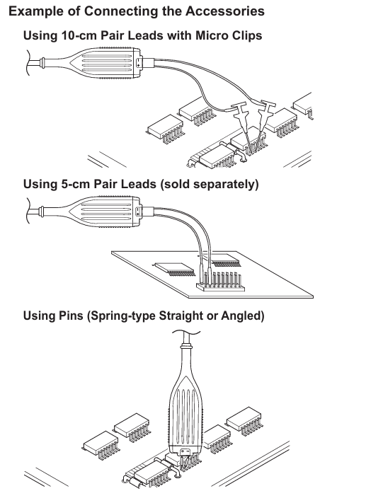
2. Key points for using accessories
Wire selection: A 10cm wire pair (including a 150 Ω damping resistor) is suitable for low-frequency signals, while a 5cm wire pair (including a 100 Ω damping resistor, sold separately) is more suitable for high-frequency signals; The crocodile clamp wire pair can directly clamp the measured point.
Pin selection: Spring type straight/bent pin (standard accessory), straight/bent pin (sold separately) suitable for high-frequency signals, need to be selected according to the pin position and status of the tested device.
Grounding extension cable: Only when measuring low-frequency signals, connect the probe grounding terminal to the common grounding of the tested equipment to reduce noise. It can be directly connected to a 0.64mm square or a Φ 0.65mm round pin.
3. Offset voltage adjustment
Adjustment timing: Adjust when there is still residual offset voltage after preheating, using an appropriate screwdriver (thickness 0.2-0.35mm, width 1.3-1.5mm, flat or cross).
Operation precautions: Do not apply excessive force to avoid damaging the internal variable resistor; Only used to adjust residual offset voltage, cannot be deliberately changed for other purposes, otherwise it may cause the probe to not meet specifications; Environmental temperature changes can affect offset voltage, and temperature should be taken into account during continuous measurements.
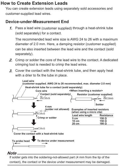
4. Custom extension cord production
Material preparation: Contact points, heat shrink tubing, flanged pins, fixed covers, and user provided wires (recommended AWG 24-26, maximum diameter 2.0mm) and damping resistors (optional) need to be purchased separately.
Production steps:
Thread the wire into the contact heat shrink tube, crimp/weld the wire core to the contact (connect in series when inserting the resistor), and heat the heat shrink tube to fix it.
The other end of the wire is threaded into the user's own heat shrink tubing and welded to the flanged pin. The heat shrink tubing is fixed (note that the tip of the pin cannot be welded within 4mm, and the diameter after heat shrink is ≤ 2.0mm).
Thread the flanges of the two input pins through the center hole of the fixed cover, align the probe head with the "+/-" mark, and install the fixed cover to ensure that the buckle is locked; Do not use the probe grounding terminal when using a fixed cover.
Product specifications
1. Electrical specifications (for use with a 50 Ω input resistance oscilloscope)
Project specifications
Frequency bandwidth (-3dB) DC to 200MHz
Attenuation ratio 10:1
DC gain accuracy (23 ± 5 ℃, preheating for 30 minutes+) ± 1% (when single ended input is 0V); Dual ended input without specifications due to CMRR characteristics
Differential input voltage range (+/- between terminals) ± 20V (DC+ACpeak)
Common mode rejection ratio (CMRR) DC: -80dB; <60Hz:-80dB; <100kHz:-70dB; <10MHz:-50dB; <100MHz: -20dB (typical value)
Input equivalent noise ≤ 4mVrms (typical value)
Input capacitance (to ground) 2pF (typical value)
Input resistance (to ground) 500k Ω (typical value)
Output resistance 50 Ω (typical value)
Rise/fall time 1.75ns (typical value)
Delay time 8.4ns
Preheating time ≥ 30 minutes
2. Input voltage derating (by frequency)
When the signal frequency increases, the maximum input voltage needs to be reduced, and the derating requirements of DC+ACpeak and ACpeak need to be met simultaneously:
Frequency maximum input voltage (DC+ACpeak) maximum input voltage (ACpeak)
DC~10MHz 60V 42V
10~151.6MHz decreases from 60V to 30V with increasing frequency, from 42V to 30V with increasing frequency
151.6~200MHz 30V 30V
3. General specifications and compliance
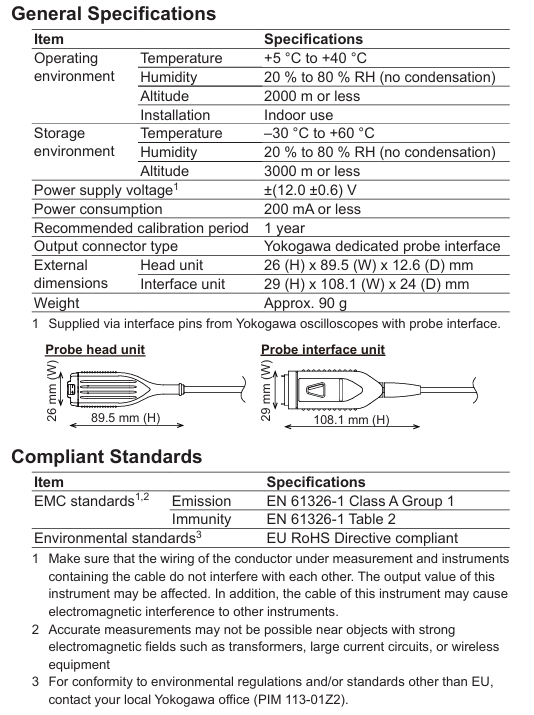
General specifications:
Project specifications
Power supply voltage ± (12.0 ± 0.6) V (powered by compatible oscilloscope interface pins)
Power consumption ≤ 200mA
Recommended calibration cycle of 1 year
Output connector type Yokogawa dedicated probe interface
Dimensions of the head unit: 26 (H) × 89.5 (W) × 12.6 (D) mm; Interface unit: 29 (H) × 108.1 (W) × 24 (D) mm
Weight approximately 90g
Compliance standards:
EMC standard: emission complies with EN 61326-1 Class A Group 1; The anti-interference degree complies with Table 2 of EN 61326-1 (note: strong electromagnetic field environments such as transformers, high current circuits, and near wireless devices may affect measurement accuracy).
Environmental standards: compliant with the EU RoHS directive; Environmental regulations in other regions require consultation with the local Yokogawa office.
Disposal: It is necessary to comply with the laws and regulations of the country/region where the product is disposed of; EU/UK must handle according to the WEEE directive and cannot mix with household waste. Contact the local Yokogawa office.
- YOKOGAWA
- Reliance
- ADVANCED
- SEW
- ProSoft
- WATLOW
- Kongsberg
- FANUC
- VSD
- DCS
- PLC
- man-machine
- Covid-19
- Energy and Gender
- Energy Access
- Renewable Integration
- Energy Subsidies
- Energy and Water
- Net zero emission
- Energy Security
- Critical Minerals
- A-B
- petroleum
- Mine scale
- Sewage treatment
- cement
- architecture
- Industrial information
- New energy
- Automobile market
- electricity
- Construction site
- HIMA
- ABB
- Rockwell
- Schneider Modicon
- Siemens
- xYCOM
- Yaskawa
- Woodward
- BOSCH Rexroth
- MOOG
- General Electric
- American NI
- Rolls-Royce
- CTI
- Honeywell
- EMERSON
- MAN
- GE
- TRICONEX
- Control Wave
- ALSTOM
- AMAT
- STUDER
- KONGSBERG
- MOTOROLA
- DANAHER MOTION
- Bentley
- Galil
- EATON
- MOLEX
- Triconex
- DEIF
- B&W
- ZYGO
- Aerotech
- DANFOSS
- KOLLMORGEN
- Beijer
- Endress+Hauser
- schneider
- Foxboro
- KB
- REXROTH
- YAMAHA
- Johnson
- Westinghouse
- WAGO
- TOSHIBA
- TEKTRONIX
- BENDER
- BMCM
- SMC
- HITACHI
- HIRSCHMANN
- XP POWER
- Baldor
- Meggitt
- SHINKAWA
- Other Brands
- UniOP
- KUKA
- IBA
- Beckhoff
-
LTI SC52.0040.0012.0000.0 - Servo Drive
-
Lti SC52.0040.0012.0000.0 - Servo Drive
-
Milton Industries LTI Tool By Milton LT1240 - 1/2" Drive Lugnut Remover
-
LTi Drives SO84.200.P030.0000.0-W - Servo Spindle Drive
-
LTI DRIVES LSP08-035-320-30-B0R1PY170 - Servo Motor
-
LTI DRIVES SE84.200.SC00.0001.0-W - Servo Drive
-
Lust CDE34.005.W2.2 - Lti Drives Controller
-
LTi SO84.012.0030.0011.2 - ServoOne Servo Drive
-
LTi Drives SO CM-P.0010.11.00.0 - Servo Drive Controller
-
LTi CDE34.017.W3.0 - Servo Drive
-
LTI Drives CDB32.004, C2.0,SH - Positioning Controller
-
LUST CM-CAN1 - LTi DRIVES Communication Module
-
LTi SO84.012.1030.0000.2 - Servo Drive
-
LTI MOOG CDE54.044 - PITCHMASTER FREQUENCY CONVERTER 181-01019
-
MOOG LTI 181-01019 CDE54.044 - PITCHMASTER FREQUENCY CONVERTER
-
Lust LTi Drives CDE34.010,D2.0 - Servo Drive Controller
-
LTI SO84.032.0003.0101.2 - Servo Drive
-
Seagate 9CC132-302 Harris LTI-CS IRT-34-0021-01 - Hard Drive 160GB
-
LTI SO84.032.0003.0001.2 - Servo Drive
-
LTI SO24.007.0070.0000.1 - SERVO CONTROLLER
-
LTi drive CDA32.003.C3.0.H05-01.PC1 - Servo Drive
-
LTI SO84.016.0030.0000.2 - SERVO CONTROLLER
-
LUST LTI CD A34.008,W1.4, BR - SERVO DRIVE
-
MOOG LTI 181-01019 CDE54.044 - PITCHMASTER FREQUENCY CONVERTER
-
LTI MOOG 181-01019 - PITCH Master Servo Drive CDE54.044
-
LTI SERVO ONE SO84.045.0030.0001.2-W - Drive
-
LUST LTi SO84.032.0040.0000.2 - SERVO ONE DRIVE
-
LTi Drives LSH-074-2-30-3 20/T1,G6.1M - SERVO MOTOR
-
LTI SO84.016.0000.0101.2 - servo drive
-
LTI SA54.0550.0033.0000.0 - Servo Drive
-
LTI SA54.0550.0033.0000.0 - Servo Drive
-
LTI LT 4850 - 3/8" Drive 3-Pc Twist Socket Transmission Drain Plug Removal System
-
LTI Tools LT4400-30 Lock Technology - 3/4" Twist Socket 1/2" Drive Lugnut Remover
-
LTI Tools LT-1400C - 1/2 Drive Wheel Torque Extension Tool
-
LTI Tools LT1250 - 1/2" Drive Dual Sided Socket Lug Nut Remover Tool
-
LTI SO84.032.0003.0101.2 - Servo Drive
-
LTI MOOG 181-01019 - PITCH Master Servo Drive CDE54.044
-
MOOG LTI 181-01019 CDE54.044 - PITCHMASTER FREQUENCY CONVERTER
-
MOOG LTI 181-01019 CDE54.044 - PITCHMASTER FREQUENCY CONVERTER
-
MOOG LTI 181-01019 CDE54.044 - PITCHMASTER FREQUENCY CONVERTER
-
LTI SA54.0550.0033.0000.0 - Servo Drive
-
LTI Tools LT-4800 - 7 Piece Twist Socket 3/8" Drive Oil Drain Plug Removal Set
-
LTI SA54.0550.0033.0000.0 - Servo Drive
-
LTI Drive SO24.007.00300000.0 - Servo Drive
-
LTI TOOLS LTI 1400-I - Drive Wheel Torque Extension
-
LTI Tools LT4400-3 - 3/4" 19mm Twist Socket 1/2" Drive Lugnut
-
LTI TOOLS LTI 1400-BB - Drive Wheel Torque Extension
-
LTI SO84.032.0003.0101.2 - Servo Drive
-
LTI Tools LT-4512 - 3/8" Drive 12mm Twist Socket
-
LTI MOTION Luster SO84.032.0003.0001.2 - Servo Drive
-
LTI Tool By Milton LT1600P - 1" Drive Torx Stick
-
LTI Lust VF1424L,HF,OP2,S56 - Variable Frequency Drive
-
LUST CDA32.004,C1.4,H08,B0 - SERVO DFRIVE CM-CAN1 Module
-
LTI SO84.045.0002.0001.2-W - Drive
-
LTI Lust VF1404M,C9,PT1,BR1 - Inverter Type VF1404M
-
LTI SA54.0550.0033.0000.0 - Servo Drive
-
LTI Tools LT-1400C - 1/2" Drive Wheel Torque Extension
-
Lust LTI DRiVES CDA32.006, C3.0, H09 - Variateur De Fr茅quence Frequency Inverter
-
LTI MOOG CDE54.044 - PITCH master SERVO DRIVE
-
LTI MOOG CDE54.044 - PITCH master SERVO DRIVE
-
LTI SO84.143.0020.0101.2-W - servo drive
-
LTI MOTION SC34.0200.0011.0000.0 - Servo drives
-
LTI SO84.032.0003.0001.2 - Servo Drive
-
LTI DRIVES GmbH MS100 - Assembly Set Mounting Kit
-
LTI SO84.032.0003.0001.2 - Servo Drive
-
LTI SO84.032.0003.0001.2 - Servo Drive
-
LTI MOTION SO84.032.0003.0101.2 - servo drive
-
LTI SO84.032.0003.0101.2 - Servo Drive
-
LTI MOOG CDE54.044 - PITCH master SERVO DRIVE
-
LTI MOTION CDE32.004.C2.4 - Servo drives
-
LTI CDD34.032锛學x.x锛孊R锛孭C1 - Servo Drive
-
Lust LTI DRiVES CDA32.006, C3.0, H09 - Inversor De Frecuencia Frequency Inverter
-
Lust SO84.008.0030.1000.0 - Servo One LTi Drive
-
LTI MOTION SO84.032.0003.0101.2 - Servo drives
-
LUST LTi CDA32.004,C1.4 - SERVO DRIVE
-
LTI MOOG CDE54.044 - PITCH Master SERVO DRIVE
-
LTI KEBA CDB32.004 C2.7, SH - PN: 08673530 Frequency Inverter
-
LTI Tools LT-1400C - 1/2" Drive Wheel Torque Extension
-
LTI LT1400-E - 1/2" Drive Wheel Torque Extension
-
LTI MOOG 181-01019 - PITCH master SERVO DRIVE CDE54.044
-
LTI LSN-097-0510-30-560/T1 - Actuator Motor
-
LTI Tools LT 4800 - 7 Piece 3/8" Drive Twist Socket Oil Drain Plug Removal System
-
LTI DRIVES GmbH MS100 - MONTAGESET Assembly Set Mounting Kit
-
Lti SC52.0040.0012.0000.0 - Servo Drive
-
LTI DRIVES GmbH MS100 - Juego De Montaje Assembly Set Mounting Kit
-
LTi DSM4-14.2-21R83-200 - Drives servomoteur Servo Motor
-
MOOG CDE 54.044.GDA - Pitch Master Industrielle Turbine Lti Drive
-
LTI SO24.004.0030.1000.0 - Servo Drive Controller
-
Lti MOOG CDE54.044 - Pitch Master Servo Drive
-
Lust LTI DRiVES CDA32.006, C3.0, H09 - Inverter
-
LTI MOTION GMBH CDB34.006,W3.0,PC1,H39 - Frequency inverter
-
LTI SO84.032.0003.0001.2 - Servo Drive
-
MOOG CDE 54.044.D - Pitch Master Industrielle Turbine Lti Drive
-
LTI TOOLS LT-1460 - 1/2" DRIVE WHEEL TORQUE EXTENSION KIT 5 PIECE SET
-
Lust Cdb32.003, C2.4 - Lti Drives Servoregulador Frecuencia Servo Controller Inverter
-
Lust LTI DRIVES CDA32.006, C3.0, H09 - Frequency Inverter
-
Lust Lti SO82.004.0030.0000.2 - Servo Drive
-
LTI MOTION SC34.0200.0011.0000.0-SL - Servo drives
-
LTI MOTION SA54.0075.0033.0000.0 - Servo drives
-
LTI MOTION SC32.0075.1011.0000.0 - Servo drives
-
LTI Servo-One Junior SO22.006.0080.1000.0 - Servo Controller Servoregler
-
LUST CDA32.004, C1.4, H08, B0 - Servo Drive & LTI CM-CAN1 Module
-
LTI DRIVES LSP08-035-320-30-B0R1PY170 - Servo Motor
-
LUST LTI CDA32.004,C1.4.H08.B0 - SERVO CONTROLLER DRIVES
-
LUST LTi DRiVES CDS44.072LC1.2 - Servo Drive
-
Lti Servo-One Junior SO22.006.0082.1000.0 - Servo Controller Servoregler
-
LUST CDA32.008,C2.0,HF - Lti DRIVES Spindle Drive Inverter
-
LTI SO22.003.0082.0000.0 - Servo Drives One junior Servo Controller Servoregler
-
Lust Lti Drives CM-CAN1 - Communication Module
-
LUST Lti Drives Vf1202s, G8, I6 - Frequency Inverter Drive
-
LTI DRIVES BR-090.03.540.UR.H38 - Bremswiderstand Brake Resistor
-
LTi DRIVES PM-E40.2DRA054P - Wind Turbine Pitch Control Inverter
-
LTi Drives GmbH br-110.01.540-UR - Brake Resistor
-
LTI Drives LSN-097-0960-30-0560/T1,S4,B - Servo Motor
-
LUST CDA34.006.C2.0 - LTI Drives Servoregler
-
LUST LTI DRIVES SERVO ONE JUNIOR SO24.002.0020.0000.1 - Servo Drive Controller
-
LTI MOTION SO84.032.0003.0001.2 - Servo drives
-
LTI DDTD750V2-120 - IBOP ACTUATOR CYLINDER FOR TOP DRIVE
-
LTI CDE32.004, C2.4 - SERVO DRIVE
-
LUST LTI DRIVES CDD34.017 W3.4PC1 - Servo Drive Controller
-
LTI CDA3208,C3,0,HF - AC SERVO DRIVE
-
LUST LTI DRIVES LSH-074-3-30-560/T1,G6.1S - SERVO MOTOR
-
LUST Lti CDB32.004.C2.4.SH - AC Servo Drive
-
LTi CDA32.006, C3.0, H09 - Servo Drive
-
LTI SO22.003.0010.0000.0 - Servo Drive Servo one junior Servoregler Controller
-
LTi Drives DSM4-14.2-21R83-200 - Servo Motor
-
LUST Lti Drives Lsh-097-1-30-560/T1, 1R - Servomotor
-
LTI 1237 - 7 Piece 1/2" Drive Flip Socket Set

K-JIANG

Add: Jimei North Road, Jimei District, Xiamen, Fujian, China
Tell:+86-15305925923