
K-WANG


WATLOW MLS Controller
WATLOW MLS Controller
MLS User's Guide "is a modular PID controller user manual released by Watlow Anfaze in 1995. It covers 16/32 loop independent control functions, supports direct connection of various sensors such as thermocouples and RTDs, and has core features such as RS-232/RS-485 serial communication, SDAC analog output, and multi job storage. It provides a one-year product warranty and needs to be used with external safety devices. The manual details the entire process of installation, operation, setting, PID tuning, and troubleshooting, and is suitable for precise control of industrial temperature, pressure, and other parameters.
Core specification parameters
Enter relevant information
Analog input: 16 channels (AIM-16 module) or 32 channels (AIM-32 module) differential input, sampling rate 16 loops/second
Sensor support: thermocouple (J/K/T/B/S/R, range -450~3210 ° F), RTD (3 ranges, RTD1: -100~300 ° C), current (0-10mA/4-20mA), voltage (-10~60mV, expandable to 0-25V)
Resolution: 0.02% (>12 bits), Accuracy: 0.1% (at 25 ° C)
Input filtering: Low pass filtering (0-255 scan period) to suppress high-frequency noise
Control and output related
Control loop: 16 loops (dual output) or 32 loops (single output), supporting On/Off, P, PI, PID control
Digital output: 34 channels (32 PID/alarm outputs+1 global alarm+1 system safety output), continuous sink current of 10mA
Output types: Time Proportional (TP), Distributed Zero Crossing Trigger (DZC), On/Off, SDAC (optional)
Cycle time: 1-255 seconds (TP output)
Communication and power related
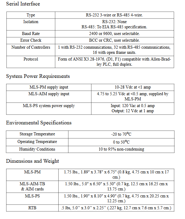
|Module | Power Parameters | Communication Parameters|
|MLS-PM | Input 10-28Vdc, current<1A | RS-232/RS-485, baud rate 2400/9600|
|MLS-AIM | Input 4.75-5.25VDC, current<0.5A | Communicate with MLS-PM through RJ12 cable|
|MLS-PS | Input 120/240Vac, Output 15Vdc (1.2A)+5Vdc (4A) | -|
|Communication protocol | Supports ANSI X3.28-1976, Allen Bradley PLC compatible protocol | Error checking: BCC/CRC optional|
Installation Guide
Module installation requirements
MLS-PM: 1/8 DIN panel installation, hole size 3.63 × 1.80 inches, weight 1.75 lbs
MLS-AIM: Size 6.5 x 5 x 7 inches, Weight 1.5 lbs, Requires 6 inches of headroom reserved
RTB terminal block: size 5.0 × 3.0 × 2.25 inches, weight 0.5 lbs, DIN rail installation
Power Supply Unit (MLS-PS): Size 1.4 x 8 x 3.9 inches, Weight 1.2 lbs
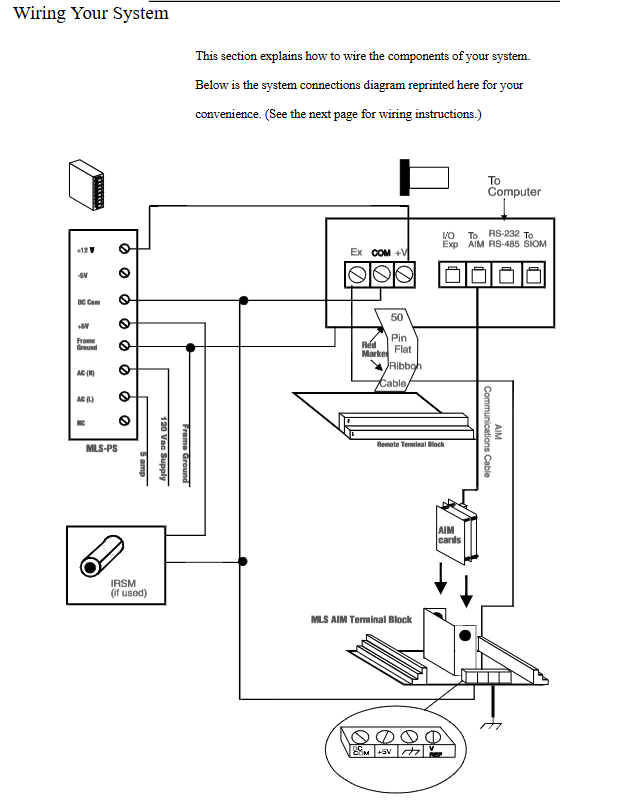
Wiring specifications
Wire gauge requirement: Priority should be given to using 18/20 AWG twisted wire to avoid excessive/insufficient wire diameter
Shielded wire usage: Input/output wires need to be shielded and grounded at one end (MLS panel grounding)
Cable recommendations: Special extension cords for thermocouples, Belden # 9154/8451 for analog inputs, Belden # 9729/9842 for communication lines
Noise suppression: When driving electromagnetic relays, a 0.01 μ F capacitor and a 47 Ω resistor need to be connected in series, or MOV/Transorb devices can be used
Key points for sensor connection
Thermocouple: Use 18/20 AWG extension wire with positive and negative electrodes connected to A+/A - to avoid grounding type thermocouples
RTD: Recommended 3-wire 100 Ω platinum resistor, wired to A+/A -/A COM
Current input: Converted into a voltage signal through a series resistor, 4-20mA corresponds to 12-60mV
Voltage input: directly connected to A+/A -, over 60mV needs to be adjusted through a scaling resistor
Operation and Settings
Front panel operation
Key functions: YES/NO (menu selection/numerical adjustment), ENTER (confirm storage), BACK (return), ALARM ACK (alarm confirmation), CHNG SP (modify set value), Man/Auto (mode switching)
Display mode:
Bar chart display: Simultaneously display the status and deviation of 8 circuits
Single loop display: displays the PV, SP, output percentage, and control status of a single loop
Alarm display: flashing to indicate high/low process/deviation alarm, sensor malfunction
Homework management: Supports storing 8 homework programs (including PID parameters, alarm settings, and set values), which can be remotely selected through digital input
Core Settings Menu
Global parameter settings
Controller address: 1-32 (unique when multiple controllers are cascaded)
Communication parameters: baud rate (2400/9600), protocol (ANASOFT/Allen Bradley), error checking (BCC/CRC)
Keyboard lock: Disable CHNG SP, Man/Auto and other keys
Power on output status: Off (default) or Memory (restore pre power off state)
Input settings
Input type: Select sensor type (thermocouple/RTD/linear/pulse/skip)
Linear scaling: Input 2 measurement points (e.g. 0PSI=4mA, 50PSI=20mA) for automatic calibration
Input offset: -300~+300, correct sensor error
Input filtering: 0-255 scan period, input signal with rapidly changing damping
Control and output settings
PID parameters: PB (proportional band), TI (integration time 0-6000 seconds), TD (differentiation time 0-255 seconds)
Output type: TP/DZC/On/Off/SDAC, SDAC supports 0-5VDC/4-20ADC switching
Output limit: 0-100%, supports continuous or timed limit (1-999 seconds)
Hot/Cold Output Configuration: Independently set PID parameters, action mode (reverse/forward), output interval
Alarm Settings
Alarm types: high/low process alarm, high/low deviation alarm, supporting three modes: Alarm/Control/Off
Alarm parameters: high/low set value (adapted to sensor range), deviation bandwidth (0-255), dead zone (0-255), delay (0-255 seconds)
Alarm output: can be allocated to 34 digital outputs, supporting multiple alarms sharing one output
Advanced features and troubleshooting
Advanced features
SDAC module: optional serial digital to analog conversion module, requiring configuration of SDAC high/low values (such as 4-20mA corresponding to 0-50PSI), occupying digital output 34 as the clock line
Remote job selection: Binary selection of 8 jobs through 1-3 digital inputs
Output forced override: triggers all circuits to switch to manual mode through digital input, and the output percentage can be customized
Linear scaling example: supports custom measurement range conversion for sensors such as pressure and flow (the manual includes 2 detailed examples)
Common troubleshooting
|Fault phenomenon | Key troubleshooting points|
|AIM communication failure | Check AIM power supply (4.75-5.25VDC), communication cable connection, manual reset controller|
|No display/button response | Check if MLS-PM power and keyboard lock function are enabled|
|Abnormal sensor reading | Confirm sensor type settings, wiring polarity, scaling resistor installation, input filtering parameters|
|Communication failure | Verify baud rate/protocol/address consistency, serial port wiring, and RS-232/RS-485 jumper settings|
|Alarm false triggering | Adjust the alarm dead zone and delay time, and check if there is noise interference in the sensor|
- YOKOGAWA
- Reliance
- ADVANCED
- SEW
- ProSoft
- WATLOW
- Kongsberg
- FANUC
- VSD
- DCS
- PLC
- man-machine
- Covid-19
- Energy and Gender
- Energy Access
- Renewable Integration
- Energy Subsidies
- Energy and Water
- Net zero emission
- Energy Security
- Critical Minerals
- A-B
- petroleum
- Mine scale
- Sewage treatment
- cement
- architecture
- Industrial information
- New energy
- Automobile market
- electricity
- Construction site
- HIMA
- ABB
- Rockwell
- Schneider Modicon
- Siemens
- xYCOM
- Yaskawa
- Woodward
- BOSCH Rexroth
- MOOG
- General Electric
- American NI
- Rolls-Royce
- CTI
- Honeywell
- EMERSON
- MAN
- GE
- TRICONEX
- Control Wave
- ALSTOM
- AMAT
- STUDER
- KONGSBERG
- MOTOROLA
- DANAHER MOTION
- Bentley
- Galil
- EATON
- MOLEX
- Triconex
- DEIF
- B&W
- ZYGO
- Aerotech
- DANFOSS
- KOLLMORGEN
- Beijer
- Endress+Hauser
- schneider
- Foxboro
- KB
- REXROTH
- YAMAHA
- Johnson
- Westinghouse
- WAGO
- TOSHIBA
- TEKTRONIX
- BENDER
- BMCM
- SMC
- HITACHI
- HIRSCHMANN
- XP POWER
- Baldor
- Meggitt
- SHINKAWA
- Other Brands
- UniOP
- KUKA
- IBA
- Beckhoff
- ADLINK
-
ADLINK HPCI-14S12U - Industrial Control Backplane 12PCI Backplane PCI-14S Passive Backplane
-
ADLINK PCIe-GIE74C - image acquisition card 4-CH GigE Vision PoE+ Frame Grabber
-
ADLINK PCI-8164 - control card 4-Axis Advanced Motion Controller Board
-
ADLINK PCIe-U304 - 4 Port USB3 PCIe Frame Grabbers USB Screw Hole Card
-
ADLINK PCI-9112 - Multi-Function Data Acquisition Card DAQ Card
-
ADLINK PCI-7432 - 51-12013-0A50 4-CH Isolated Numérique I/O PCI Cartes Digital I/O Card
-
ADLINK PCA-6106P3-0C1 REV.C1 - backplane 6-Slot Passive Backplane Board
-
ADLINK PCI-7224 - 24-CH Opto-Isolated Digital I/O PCI Board
-
ADLINK CPCI-7433R(G) - Digital Input Board Rear I/O CompactPCI Card
-
ADLINK EBP-13E4 - 51-46703-0A30 Industrial PC Backplane Passive Backplane
-
ADLINK PCIE-HDV62 - Image acquisition card High Definition Video Frame Grabber
-
ADLINK EBP-13E4 - 51-46703-0A30 Industrial Backplane Board Passive Backplane
-
ADLINK 90111-B1 / CPCI-6770 - PCB CPU MODULE CompactPCI Single Board Computer
-
ADLINK PCI-7248 - DATA ACQUISITION PCI CARD 48-CH Parallel Digital I/O Board
-
ADLINK PCI-7230 - 51-12003-0a50 board PCI7230 32-CH Isolated Digital I/O Card
-
ADLINK PCI2A000CB - 51-20000-0B30 Multi-Function DAQ Card Baseboard
-
ADLINK PCI-8134-005 - 4-Axis Motion Controller Card
-
ADLINK PCI-7224 - 24-CH Opto-Isolated Digital I/O PCI Card
-
ADLINK PCI-7434 - 64-CH Isolated Digital Output Card
-
ADLINK PCI-8132 - motion control card 2-Axis Servo & Stepper Controller
-
ADLINK PCI-8134 - Motion Controller PCI Card 4-Axis Controller Board
-
ADLINK PCI-8164 - Motion Control Card 51-12406-0A40 4-Axis Controller
-
ADLINK 51-12001-0C20 - Circuit Board Data Acquisition Interface Module Hardware
-
ADLINK NuPR0-840 - industrial control motherboard Full-Size PICMG CPU Board
-
ADLINK PCI-7444 - 51-12023-0A10 card 128-CH Isolated Digital Output Board
-
ADLINK PCI-1612B - data acquisition card 4-Port RS-232/422/485 Serial Communication Card
-
ADLINK PCI-6208V 009 - 8/16-CH 16-Bit Analog Output Cards PCB-I-E-482=6BX3
-
ADLINK NUPRO-935A/LV - industrial control motherboard Full-Size PICMG SBC Board
-
ADLINK PCI-9114DG - Multi-Function DAQ Card Data Acquisition PCI Card
-
ADLINK ACL-7130 - Data acquisition card Isolated Digital I/O Board
-
ADLINK ABX-6300D-4E1-BP - board ABX6300D4E1BP Video Interface Expansion Card
-
ADLINK CPCI-6940 - CPCI-6940/D1539/M16-0(EA)-000E 6U CompactPCI Processor Board
-
ADLINK NuPRO-760 - industrial control motherboard Half-Size PICMG SBC CPU Board
-
ADLINK IMB-M42H (G)-0020 - industrial control motherboard LGA1155 Micro-ATX Mainboard
-
ADLINK RTV-24 / PCI-MP4S - 51-12519-1C30 4-Channel Real Time Video Capture Board
-
ADLINK PCI-8134 - 4-Axis Servo & Stepper Motion Controller Card
-
ADLINK MXC-6101D - V.PC000.002.ST.00 Box PC Configurable Embedded Computer
-
ADLINK PCI-8134A - 51-12421-0A10 Motion Control Card 4-Axis Controller Card
-
ADLINK DIN-100S / DIN-100SA1 - Technology SCSI-II TB 100-PIN Terminal Block Board
-
ADLINK DIN-812M001 / DIN812M001 - 51-14034-0A1 51140340A1 Terminal Module Breakout Interface
-
ADLINK PCI-8164 - Servo motion control 4-Axis Advanced Controller Card
-
ADLINK PCIe-GIE64 - Acquisition card GigE Vision PoE+ Frame Grabber
-
ADLINK M-302 - Industrial control motherboard ATX PC Board Mainboard
-
ADLINK PCI-8134 - Motion Controller PCI Card 4-Axis Controller Board
-
ADLINK PCI-RTV24 - Image capture card Analog Video Frame Grabber
-
ADLINK PCI-8102 - Motion control card 2-Axis Servo & Stepper Controller Board
-
ADLINK PCI-9112 REV.B1 - Card Multi-Function Data Acquisition Card
-
ADLINK HSI-DI32-M-N / HSL-TB32-M-DIN - Discrete I/O MODULE Distributed Automation Module System
-
ADLINK PCI-7296 - IO card REV.A3 96-CH Parallel Digital I/O Card
-
ADLINK DIN-814P-A4 / 814Y - terminal board Motion Control Interface Block
-
ADLINK DIN-814P-A4 - 51-14056-0A10 PCB-I-E-2736=ZA01 Screw Terminal Board Breakout
-
ADLINK M-322 - motherboard Industrial Control Computer Mainboard
-
ADLINK NUPRO-406 REV:B1 - industrial control motherboard Full-Size PICMG CPU Board
-
ADLINK AMP-204C - card DSP-Based 4-Axis Advanced Pulse-Train Controller
-
ADLINK HPCI14S REV.B1 - industrial computer baseboard 14-Slot Passive Backplane
-
ADLINK PCI-7250 - 8-CH Relay Output & 8-CH Isolated DI PCI Card
-
ADLINK EBP-13E2 - baseplate Passive Backplane Industrial Computer Chassis Board
-
ADLINK LPCI-3488A - PCI-GPIB card 51-12801-0A30 acquisition card IEEE-488 Interface Board
-
ADLINK PCI-6216V-GL - 51-12201-0C30 16-CH 16-Bit Voltage Analog Output Card
-
ADLINK ACL-8454 - 16-CH Isolated Digital I/O & 4-CH Counter Card
-
ADLINK HPCI-9S7U - backplane Passive Backplane Compatible with NuPRO-A301 852 841 842
-
ADLINK DAQ-2010-007 - Simultaneous-Sampling Multi-Function Data Acquisition Card
-
ADLINK MP-C154 - 51-64205-0A10 Motion Control Card 4-Axis Controller Board
-
ADLINK MXE-202/mSSD16B/WiFi-BT - Matrix Rugged I/O Platform Embedded Fanless Computer
-
ADLINK CM-920-R-17 - PC/104-Plus Single Board Computer Module Intel Celeron M
-
ADLINK PCI-7250 NSMP - 8-CH Relay Output & 8-CH Isolated DI Card
-
ADLINK PCI-8164 - 4-Axis Motion Controller PCI Card W/ Cable and Breakout Box
-
ADLINK EMX-100 - Ethernet-based 4-axis Motion Controllers Distributed Motion Module
-
ADLINK PCI-8134A - Press control card 4-Axis Motion Controller Board
-
ADLINK M-845EG REV:3.2 - industrial motherboard Pentium 4 Socket 478 Micro-ATX
-
ADLINK PCI-9114A Rev A2 DG - card High-Resolution Multi-Function Data Acquisition Board
-
ADLINK IEC-915GV - REV 1.1 Industrial motherboard Socket 478 CPU Board
-
ADLINK PCI-9111DG(G) - Data Acquisition Card Multi-Function DAQ Card
-
ADLINK HPCI-15S10 REV:B2 - Industrial computer base plate Passive Backplane Board
-
ADLINK NuPR0-840 / NuPR0-840DV - industrial control motherboard Full-size PICMG CPU Board
-
ADLINK RTV-24 / PCI-MP4S - 51-12519-1C30 4-Channel Real Time Video Capture Board
-
ADLINK NUPRO-780 - industrial control motherboard Pentium III Single Board Computer
-
ADLINK PCI-7296 - 0050 card 96-CH Opto-Isolated Parallel DIO Card Set
-
ADLINK NUPRO-780 - industrial control motherboard PICMG Full-Size SBC
-
ADLINK PCI-7248 - 51-12006-0A3 002 Pci 7248 48-CH Parallel Digital I/O Card
-
ADLINK PCI-7230 - 32-CH Isolated Digital I/O Card
-
ADLINK AMP-204C - motion control card 4-Axis Advanced Controller Board
-
ADLINK PCI-1714UL - Card Ultra High-Speed 4-CH Simultaneous Sampling DAQ
-
ADLINK NuPRO-E330 - industrial computer equipment motherboard PICMG 1.3 SHB SBC
-
ADLINK AMP-204C - DSP-Based 4-Axis Advanced Pulse-Train Motion Controller Module
-
ADLINK PCI-7256 - 001 51-12206-0A2 REV.A2 LPCI-7256 16-CH Latching Relay Output Card
-
ADLINK ND6050 - NUDAM DIGITAL I/0 MODULE Distributed I/O Unit
-
ASEM BM100 - Box PC Embedded Fanless Industrial Computer
-
ADLINK PCI-7250 - PCI Acquisition Card 8-CH Relay Output & Isolated DI Board
-
ADLINK PCI-8164 - Servo motion control 4-Axis Controller Card
-
ADLINK NuPRO-A40H - Industrial Motherboard 51-41807-1A30 OSP LGA1155 H61
-
ADLINK ADMAX X300 SERVER - 51066010-0A30 motherboard Multi-Processor Mainboard
-
ADLINK CMe-GIE62+ - 51-32903-0A30 control card PC/104-Plus GigE Vision Frame Grabber
-
ADLINK NUPRO-780 - industrial control motherboard Full-Size PICMG SBC CPU Board
-
ADLINK ETX-AT-N270-18/GKTEL - 51-71111-OB10 motherboard ETX CPU Module Board
-
ADLINK DIN-812M - interface module Terminal Block Connection Board
-
ADLINK IMB-M42H - industrial control motherboard LGA1155 Micro-ATX Mainboard
-
ADLINK PXIS-2508 - 8-slot 3U PXI Instrument Chassis Power Hardware Assembly
-
ADLINK AMP-208C - Motion Control card DSP-Based 8-Axis Pulse-Train Controller
-
ADLINK PCI-9111 / PCI-9111DG - Multi-Function Data Acquisition Card DAQ Board
-
ADLINK IEEE-488 GPIB card - Bus Interface Controller Communication Board
-
ADLINK RTV-24 - 51-12519-1C30 image acquisition card Video Frame Grabber Card
-
ADLINK TB-24P/24-01 - Board 24 Way Screw Terminal Breakout Board
-
ADLINK HSL-DI16DO16-DB-NN - 51-23015-0A40 Distributed Discrete I/O Module Set
-
ADLINK PCI-7442 - switch quantity card data acquisition card 64-CH Isolated Card
-
ADLINK ACL-7130 REV. B2 - industrial control capture card Isolated Digital I/O PCI Card
-
ADLINK PCI-6S / PCI6S - Backplane 6-Slot Passive Backplane Chassis Board
-
ADLINK ACL-8113A - card Isolated Digital Input Card
-
ADLINK CPCI-6208V-003 - board cPCI CompactPCI 8-CH Analog Output Card
-
ADLINK DIN-100S-01(G) - SCSI 100-Pin Terminal Block Interface Board
-
ADLINK PCI-7433 - Isolated Digital Input Card 64-CH
-
ADLINK PCI-9812 - Synchronous sampling analog input card High-Speed DAQ Board
-
ADLINK PCI-7434 REV.B1 - PLOTECH PCB-I-E-1182=6EX2 64-CH Isolated Digital Output Card
-
ADLINK PCIe-RTV24 - 51-18016-0A20 4-CH Real-Time Video Capture Card PCIe Frame Grabber
-
ADLINK PCI-8144 / PCI-8144N - Motion control card 4-Axis Stepper Motor Controller
-
ADLINK DIN-68S-01 - terminal board 68-Pin Connector Terminal Block
-
ADLINK MP-C154 - Motion control card 4-Axis Advanced Controller Card
-
ADLINK PCI-7248 (G) - Motherboard 48-CH Parallel Digital I/O Card
-
ADLINK MXE-1301(G) - Intel Atom D2550+NM10 MXE 1300 Series 93-4130-0030 Embedded Computer
-
ADLINK PRO-841 Rev 2.0 / PRO-060907000670 - CPU 2.26GHz & RAM Industrial PC Board
-
ADLINK NuPRO-E330 - Industrial Motherboard System Host Board PICMG 1.3 SHB
-
ADLINK EBP-13E2 - Passive Backplane Industrial Chassis Baseboard
-
ADLINK PCI-8154 - 4-axis Motion Control Card Servo & Stepper Controller Board
-
ADLINK NuPrO-596 REV.B1 - industrial control motherboard Half-size PICMG CPU Board
-
ADLINK PCI-7852 / PCI-7851 - PLOTECH High-Speed Link Control Card Interface Board
-
ADLINK PCI-9112 - 51-12252-0D20 data acquisition card Multi-Function DAQ
-
ADLINK PCI-9112 - Circuit Board 51-12252-0C20 Multi-Function Data Acquisition Card
-
ADLINK NUPRO-761 REV:1.1 - industrial control motherboard PICMG Full-Size CPU Board

K-JIANG

Add: Jimei North Road, Jimei District, Xiamen, Fujian, China
Tell:+86-15305925923