
K-WANG


HIMA X-AO 16 01 HIMax ® Analog Output Module
HIMA X-AO 16 01 HIMax ® Analog Output Module
Core technical specifications
(1) Electrical and output parameters
Category specific specifications
Supply voltage 24 VDC (allowable range: -15%~+20%), SELV/PELV standard
Input current maximum 1.3A, minimum 0.6A (when all outputs are turned off), 80mA per channel
Output channel single channel connection: 16; Redundant connections: 8 (only odd numbered channels AO1, AO3... AO15)
Output range nominal: 4~20 mA; operating: 0~23 mA
Resolution and accuracy 16 bits (10000 digits in SILworX), LSB ≤ 2 µ A; accuracy at 25 ℃ ≤ ± 0.2% full scale, full temperature range ≤ ± 0.5% full scale
Load capacity: maximum resistance of 600 Ω, maximum inductance of 1mH, maximum capacitance of 100 µ F (parallel resistance load)
The response characteristic establishment time is 5ms, and the fault shutdown time is 16ms (in accordance with the principle of "power-off tripping")
(2) Environmental and physical parameters
Working temperature: 0~+60 ℃, storage temperature: -40~+85 ℃
Humidity: Maximum 95% relative humidity (without condensation)
Protection level: IP20
Dimensions (H × W × D): 310 × 29.2 × 230 mm, weight approximately 1.2kg
Altitude:<2000m, pollution level: Level II (IEC/EN 61131-2)
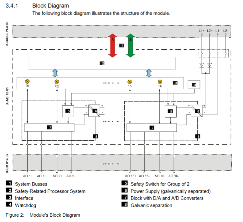
Hardware composition and connection
(1) Compatible connector board
Model, type, and purpose
X-CB 014 01 single channel, screw terminal single module screw terminal wiring
X-CB 014 02 redundant, screw terminal dual module redundant screw terminal wiring
X-CB 014 03 Single Channel, Cable Plug Single Module Cable Plug Wiring
X-CB 014 04 redundancy, cable plug dual module redundant cable plug wiring
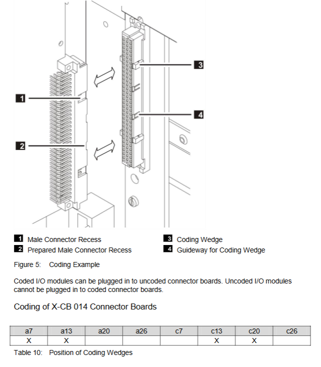
Mechanical coding: The connector board and module are protected against accidental insertion through wedge-shaped coding, and the coding position follows the X-CB 014 series specifications
(2) System cable
Model: X-CA 011 (LIYCY-TP 18 × 2 × 0.25 mm ²)
Length: standard 8m, 15m, 30m, minimum bending radius: fixed installation 5 x cable outer diameter, flexible application 10 x cable outer diameter
Characteristics: Flame retardant and self extinguishing (compliant with IEC 60332-1-2/-2-2), color coding follows DIN 47100
(3) Wiring method
Single channel wiring: Use X-CB 014 01/03 to directly connect the actuator
Redundant wiring (serial): using X-CB 014 02/04, dual modules installed adjacent to each other, sharing actuators
Closed loop control: AO output → actuator → AI input (such as X-AI 32 01) → processor module, forming a feedback loop
FTA connection: Through X-FTA 002 01/X-FTA 009 02, connect the module to the on-site terminal components via system cables
HART communication: The handheld device is connected in parallel at both ends of the actuator, and the residual error after compensating for communication current fluctuations is ≤ 2% of the full range
Configuration and Operation (Based on SILworX Tool)
(1) Core configuration items
Key parameter description for configuring labels
Module Noise Blanking is activated by default, and the processor module delays response to transient faults
Missing modules in the redundant group of Spare Modules are not considered as faults and are automatically shut down by default
I/O submodule AO16_01 Background Test Error: True=Test Fault, False=Normal
I/O submodule AO16_01 Restart on Error Force the faulty module to restart and self check, default shutdown
The default mapping value for Channels 4mA/20mA is 4.0/20.0, and unused channels should be kept as default
After activating Channels redundancy, it is added to the redundancy group and is turned off by default
Channels status (Channel OK): True=Channel normal, False=Channel fault (output set to 0)
(2) Diagnostic status code
Module Status: 32-bit WORD, such as 0x00000001=module fault, 0x00000010=L1+voltage fault
Submodule Status: For example, 0x00000040=module shutdown due to overcurrent, 0x00000010=temperature threshold 1 overtemperature
Channel diagnosis: supports open circuit detection (OC) and OC Monitoring Defect
Safety and maintenance requirements
(1) Security protection
ESD protection: Only authorized personnel with ESD knowledge are allowed to operate, and must wear anti-static wristbands. Unused modules must be stored in their original packaging
Fault response: In case of module failure, all outputs should be turned off within 16ms; When there is a channel failure, turn off the corresponding channel group (2 channels), and the Error LED will light up
Ex area use: Additional explosion-proof measures need to be taken to avoid sparks caused by plugging and unplugging loaded connectors
(2) Maintenance and disposal
Verification testing: to be conducted every 10 years, refer to the security manual HI 801 003 E
Operating system update: Use system downtime to load the latest version, modules need to be in STOP state
Repair authorization: Only HIMA company has the right to repair, unauthorized intervention will result in safety function failure and warranty failure
Transportation and discontinuation: Original packaging is required for transportation (to prevent ESD and mechanical damage); Discontinuation requires disassembly from the substrate and disposal according to environmental requirements
- YOKOGAWA
- Reliance
- ADVANCED
- SEW
- ProSoft
- WATLOW
- Kongsberg
- FANUC
- VSD
- DCS
- PLC
- man-machine
- Covid-19
- Energy and Gender
- Energy Access
- Renewable Integration
- Energy Subsidies
- Energy and Water
- Net zero emission
- Energy Security
- Critical Minerals
- A-B
- petroleum
- Mine scale
- Sewage treatment
- cement
- architecture
- Industrial information
- New energy
- Automobile market
- electricity
- Construction site
- HIMA
- ABB
- Rockwell
- Schneider Modicon
- Siemens
- xYCOM
- Yaskawa
- Woodward
- BOSCH Rexroth
- MOOG
- General Electric
- American NI
- Rolls-Royce
- CTI
- Honeywell
- EMERSON
- MAN
- GE
- TRICONEX
- Control Wave
- ALSTOM
- AMAT
- STUDER
- KONGSBERG
- MOTOROLA
- DANAHER MOTION
- Bentley
- Galil
- EATON
- MOLEX
- Triconex
- DEIF
- B&W
- ZYGO
- Aerotech
- DANFOSS
- KOLLMORGEN
- Beijer
- Endress+Hauser
- schneider
- Foxboro
- KB
- REXROTH
- YAMAHA
- Johnson
- Westinghouse
- WAGO
- TOSHIBA
- TEKTRONIX
- BENDER
- BMCM
- SMC
- HITACHI
- HIRSCHMANN
- XP POWER
- Baldor
- Meggitt
- SHINKAWA
- Other Brands
- UniOP
- KUKA
- IBA
- Beckhoff
-
LTI SC52.0040.0012.0000.0 - Servo Drive
-
Lti SC52.0040.0012.0000.0 - Servo Drive
-
Milton Industries LTI Tool By Milton LT1240 - 1/2" Drive Lugnut Remover
-
LTi Drives SO84.200.P030.0000.0-W - Servo Spindle Drive
-
LTI DRIVES LSP08-035-320-30-B0R1PY170 - Servo Motor
-
LTI DRIVES SE84.200.SC00.0001.0-W - Servo Drive
-
Lust CDE34.005.W2.2 - Lti Drives Controller
-
LTi SO84.012.0030.0011.2 - ServoOne Servo Drive
-
LTi Drives SO CM-P.0010.11.00.0 - Servo Drive Controller
-
LTi CDE34.017.W3.0 - Servo Drive
-
LTI Drives CDB32.004, C2.0,SH - Positioning Controller
-
LUST CM-CAN1 - LTi DRIVES Communication Module
-
LTi SO84.012.1030.0000.2 - Servo Drive
-
LTI MOOG CDE54.044 - PITCHMASTER FREQUENCY CONVERTER 181-01019
-
MOOG LTI 181-01019 CDE54.044 - PITCHMASTER FREQUENCY CONVERTER
-
Lust LTi Drives CDE34.010,D2.0 - Servo Drive Controller
-
LTI SO84.032.0003.0101.2 - Servo Drive
-
Seagate 9CC132-302 Harris LTI-CS IRT-34-0021-01 - Hard Drive 160GB
-
LTI SO84.032.0003.0001.2 - Servo Drive
-
LTI SO24.007.0070.0000.1 - SERVO CONTROLLER
-
LTi drive CDA32.003.C3.0.H05-01.PC1 - Servo Drive
-
LTI SO84.016.0030.0000.2 - SERVO CONTROLLER
-
LUST LTI CD A34.008,W1.4, BR - SERVO DRIVE
-
MOOG LTI 181-01019 CDE54.044 - PITCHMASTER FREQUENCY CONVERTER
-
LTI MOOG 181-01019 - PITCH Master Servo Drive CDE54.044
-
LTI SERVO ONE SO84.045.0030.0001.2-W - Drive
-
LUST LTi SO84.032.0040.0000.2 - SERVO ONE DRIVE
-
LTi Drives LSH-074-2-30-3 20/T1,G6.1M - SERVO MOTOR
-
LTI SO84.016.0000.0101.2 - servo drive
-
LTI SA54.0550.0033.0000.0 - Servo Drive
-
LTI SA54.0550.0033.0000.0 - Servo Drive
-
LTI LT 4850 - 3/8" Drive 3-Pc Twist Socket Transmission Drain Plug Removal System
-
LTI Tools LT4400-30 Lock Technology - 3/4" Twist Socket 1/2" Drive Lugnut Remover
-
LTI Tools LT-1400C - 1/2 Drive Wheel Torque Extension Tool
-
LTI Tools LT1250 - 1/2" Drive Dual Sided Socket Lug Nut Remover Tool
-
LTI SO84.032.0003.0101.2 - Servo Drive
-
LTI MOOG 181-01019 - PITCH Master Servo Drive CDE54.044
-
MOOG LTI 181-01019 CDE54.044 - PITCHMASTER FREQUENCY CONVERTER
-
MOOG LTI 181-01019 CDE54.044 - PITCHMASTER FREQUENCY CONVERTER
-
MOOG LTI 181-01019 CDE54.044 - PITCHMASTER FREQUENCY CONVERTER
-
LTI SA54.0550.0033.0000.0 - Servo Drive
-
LTI Tools LT-4800 - 7 Piece Twist Socket 3/8" Drive Oil Drain Plug Removal Set
-
LTI SA54.0550.0033.0000.0 - Servo Drive
-
LTI Drive SO24.007.00300000.0 - Servo Drive
-
LTI TOOLS LTI 1400-I - Drive Wheel Torque Extension
-
LTI Tools LT4400-3 - 3/4" 19mm Twist Socket 1/2" Drive Lugnut
-
LTI TOOLS LTI 1400-BB - Drive Wheel Torque Extension
-
LTI SO84.032.0003.0101.2 - Servo Drive
-
LTI Tools LT-4512 - 3/8" Drive 12mm Twist Socket
-
LTI MOTION Luster SO84.032.0003.0001.2 - Servo Drive
-
LTI Tool By Milton LT1600P - 1" Drive Torx Stick
-
LTI Lust VF1424L,HF,OP2,S56 - Variable Frequency Drive
-
LUST CDA32.004,C1.4,H08,B0 - SERVO DFRIVE CM-CAN1 Module
-
LTI SO84.045.0002.0001.2-W - Drive
-
LTI Lust VF1404M,C9,PT1,BR1 - Inverter Type VF1404M
-
LTI SA54.0550.0033.0000.0 - Servo Drive
-
LTI Tools LT-1400C - 1/2" Drive Wheel Torque Extension
-
Lust LTI DRiVES CDA32.006, C3.0, H09 - Variateur De Fr茅quence Frequency Inverter
-
LTI MOOG CDE54.044 - PITCH master SERVO DRIVE
-
LTI MOOG CDE54.044 - PITCH master SERVO DRIVE
-
LTI SO84.143.0020.0101.2-W - servo drive
-
LTI MOTION SC34.0200.0011.0000.0 - Servo drives
-
LTI SO84.032.0003.0001.2 - Servo Drive
-
LTI DRIVES GmbH MS100 - Assembly Set Mounting Kit
-
LTI SO84.032.0003.0001.2 - Servo Drive
-
LTI SO84.032.0003.0001.2 - Servo Drive
-
LTI MOTION SO84.032.0003.0101.2 - servo drive
-
LTI SO84.032.0003.0101.2 - Servo Drive
-
LTI MOOG CDE54.044 - PITCH master SERVO DRIVE
-
LTI MOTION CDE32.004.C2.4 - Servo drives
-
LTI CDD34.032锛學x.x锛孊R锛孭C1 - Servo Drive
-
Lust LTI DRiVES CDA32.006, C3.0, H09 - Inversor De Frecuencia Frequency Inverter
-
Lust SO84.008.0030.1000.0 - Servo One LTi Drive
-
LTI MOTION SO84.032.0003.0101.2 - Servo drives
-
LUST LTi CDA32.004,C1.4 - SERVO DRIVE
-
LTI MOOG CDE54.044 - PITCH Master SERVO DRIVE
-
LTI KEBA CDB32.004 C2.7, SH - PN: 08673530 Frequency Inverter
-
LTI Tools LT-1400C - 1/2" Drive Wheel Torque Extension
-
LTI LT1400-E - 1/2" Drive Wheel Torque Extension
-
LTI MOOG 181-01019 - PITCH master SERVO DRIVE CDE54.044
-
LTI LSN-097-0510-30-560/T1 - Actuator Motor
-
LTI Tools LT 4800 - 7 Piece 3/8" Drive Twist Socket Oil Drain Plug Removal System
-
LTI DRIVES GmbH MS100 - MONTAGESET Assembly Set Mounting Kit
-
Lti SC52.0040.0012.0000.0 - Servo Drive
-
LTI DRIVES GmbH MS100 - Juego De Montaje Assembly Set Mounting Kit
-
LTi DSM4-14.2-21R83-200 - Drives servomoteur Servo Motor
-
MOOG CDE 54.044.GDA - Pitch Master Industrielle Turbine Lti Drive
-
LTI SO24.004.0030.1000.0 - Servo Drive Controller
-
Lti MOOG CDE54.044 - Pitch Master Servo Drive
-
Lust LTI DRiVES CDA32.006, C3.0, H09 - Inverter
-
LTI MOTION GMBH CDB34.006,W3.0,PC1,H39 - Frequency inverter
-
LTI SO84.032.0003.0001.2 - Servo Drive
-
MOOG CDE 54.044.D - Pitch Master Industrielle Turbine Lti Drive
-
LTI TOOLS LT-1460 - 1/2" DRIVE WHEEL TORQUE EXTENSION KIT 5 PIECE SET
-
Lust Cdb32.003, C2.4 - Lti Drives Servoregulador Frecuencia Servo Controller Inverter
-
Lust LTI DRIVES CDA32.006, C3.0, H09 - Frequency Inverter
-
Lust Lti SO82.004.0030.0000.2 - Servo Drive
-
LTI MOTION SC34.0200.0011.0000.0-SL - Servo drives
-
LTI MOTION SA54.0075.0033.0000.0 - Servo drives
-
LTI MOTION SC32.0075.1011.0000.0 - Servo drives
-
LTI Servo-One Junior SO22.006.0080.1000.0 - Servo Controller Servoregler
-
LUST CDA32.004, C1.4, H08, B0 - Servo Drive & LTI CM-CAN1 Module
-
LTI DRIVES LSP08-035-320-30-B0R1PY170 - Servo Motor
-
LUST LTI CDA32.004,C1.4.H08.B0 - SERVO CONTROLLER DRIVES
-
LUST LTi DRiVES CDS44.072LC1.2 - Servo Drive
-
Lti Servo-One Junior SO22.006.0082.1000.0 - Servo Controller Servoregler
-
LUST CDA32.008,C2.0,HF - Lti DRIVES Spindle Drive Inverter
-
LTI SO22.003.0082.0000.0 - Servo Drives One junior Servo Controller Servoregler
-
Lust Lti Drives CM-CAN1 - Communication Module
-
LUST Lti Drives Vf1202s, G8, I6 - Frequency Inverter Drive
-
LTI DRIVES BR-090.03.540.UR.H38 - Bremswiderstand Brake Resistor
-
LTi DRIVES PM-E40.2DRA054P - Wind Turbine Pitch Control Inverter
-
LTi Drives GmbH br-110.01.540-UR - Brake Resistor
-
LTI Drives LSN-097-0960-30-0560/T1,S4,B - Servo Motor
-
LUST CDA34.006.C2.0 - LTI Drives Servoregler
-
LUST LTI DRIVES SERVO ONE JUNIOR SO24.002.0020.0000.1 - Servo Drive Controller
-
LTI MOTION SO84.032.0003.0001.2 - Servo drives
-
LTI DDTD750V2-120 - IBOP ACTUATOR CYLINDER FOR TOP DRIVE
-
LTI CDE32.004, C2.4 - SERVO DRIVE
-
LUST LTI DRIVES CDD34.017 W3.4PC1 - Servo Drive Controller
-
LTI CDA3208,C3,0,HF - AC SERVO DRIVE
-
LUST LTI DRIVES LSH-074-3-30-560/T1,G6.1S - SERVO MOTOR
-
LUST Lti CDB32.004.C2.4.SH - AC Servo Drive
-
LTi CDA32.006, C3.0, H09 - Servo Drive
-
LTI SO22.003.0010.0000.0 - Servo Drive Servo one junior Servoregler Controller
-
LTi Drives DSM4-14.2-21R83-200 - Servo Motor
-
LUST Lti Drives Lsh-097-1-30-560/T1, 1R - Servomotor
-
LTI 1237 - 7 Piece 1/2" Drive Flip Socket Set

K-JIANG

Add: Jimei North Road, Jimei District, Xiamen, Fujian, China
Tell:+86-15305925923