
K-WANG


Eaton XV-102 Touch Screen Display
Eaton XV-102 Touch Screen Display
Eaton XV-102 is an industrial grade touch display screen that combines HMI (Human Machine Interface) and integrated HMI/PLC functions, suitable for mechanical manufacturing, system integration and other scenarios. It can achieve equipment monitoring, parameter setting and process control, with multiple size models, rich communication interfaces and industrial grade protection performance, and meets multiple international safety and industry certification standards.
Product positioning and core functions
Functional positioning: It can be used as an independent HMI terminal or integrated HMI/PLC device, with the core used for monitoring, operating, and controlling machines and systems in industrial scenarios. It does not support safety functions related to personnel or equipment safety protection.
Applicable scenarios: Mainly aimed at the fields of mechanical manufacturing and system construction, it can also be used in maritime scenarios through classification certification (DNV GL), and must meet specific installation and protection requirements.

Product model and hardware configuration
1. Equipment model classification
XV-102 offers three screen sizes (3.5 inches, 5.7 inches, 7.0 inches) and multiple versions (A/B/D/E/H types), with core differences reflected in display performance, communication interfaces, and expansion functions. The specific parameters are shown in the table below:
Model Version Screen Specification (Size/Resolution/Color) Core Interface Configuration Special Function Model Example
Version A 3.5-inch TFT-LCD (QVGA/32 grayscale) Ethernet USB Device, Optional Profibus/RS232/RS485/CAN 1 SD card slot, no additional expansion XV-102-A2-35MQR
Version B 3.5-inch TFT-LCD (QVGA/32 grayscale or 64K color) Ethernet USB Device, Optional RS232/RS485/CAN/Profibus/SmartWire DT Master 1 SD card slot, supports SmartWire DT Master (some models) XV-102-BE-35TQR
Version D 5.7-inch (VGA/64K color), 7.0-inch (WVGA/64K color) Ethernet USB Device/Host, Optional RS232/RS485/CAN/Profibus 1 SD card slot, large screen compatible with complex interface XV-102-D8-70TWR
Version E 5.7-inch (VGA/64K color), 7.0-inch (WVGA/64K color) Ethernet USB Device/Host, Support RS485+CAN/Profibus+SmartWire DT Master 1 SD card slot, enhance SmartWire DT integration XV-102-E6-57TVR
Version H 3.5/5.7/7.0 inches (64K colors) Ethernet, USB Device/Host (only 5.7/7.0 inches), optional RS232/RS485 basic communication function, suitable for simplified scenarios XV-102-H3-57TVR
Packaging and Accessories
The packaging contents of devices of different sizes may vary slightly, and the core accessories are as follows:
3.5-inch device: 1 touch screen, 4 mounting brackets with top wires, 1 sealing strip, 1 power connector (models with SmartWire DT include an additional SmartWire DT power connector).
5.7-inch device: 1 touch screen, 6 mounting brackets, 1 sealing strip, 1 power connector (models with SmartWire DT include an additional dedicated power connector).
7.0-inch device: 1 touch screen, 8 mounting brackets, 1 sealing strip, 1 power connector (models with SmartWire DT include an additional dedicated power connector).
Optional accessories: 10 touch pens (model ACCESSORIES-TP-TEN-10, item number 139808), need to be ordered separately.

Safety regulations and equipment protection
1. Core security warning
The manual clearly divides the danger level and provides protection requirements. The key warnings are as follows:
Hazard type, risk description, protective measures
Explosion risk: In the potentially explosive environment of Zone 22, disconnecting the live interface or mechanical impact may cause an explosion. It is only used in non hazardous areas or Zone 22; Grounding resistance<10 ΩΩ; Avoid mechanical impact; After power failure, unplug and plug the interface again
There are live parts inside the electric shock risk equipment, and opening the cover may cause electric shock. Do not open the cover by yourself; Only operated by professionals
Static electricity damage: Static discharge may damage electronic components by touching grounded metal before coming into contact with equipment, releasing static electricity; Avoid touching interface pins
Data loss: When reading or writing from an SD card, power failure or unplugging the card may cause data damage. Only when the device is powered off and the SD card is unplugged or unplugged; Reduce SD card write operations (limited write life)
When a sudden change in temperature and humidity caused by a condensation short circuit leads to internal condensation of the equipment, it is forbidden to power on the equipment; Start up after the temperature stabilizes
2. Personnel and operational requirements
Personnel qualifications: Installation and operation personnel need to have industrial automation equipment operation qualifications, be familiar with this manual and relevant safety standards (such as UL 508, IEC/EN 61131-2).
Operating standards: The complete manual must be used (it is prohibited to split a single page for use to avoid missing safety information); Strictly follow the manual requirements for installation, wiring, and maintenance, and unauthorized modification of equipment is prohibited.
Installation and interface configuration
1. Installation requirements
(1) Environmental and location conditions
General requirements: Installed in control cabinets, control panels, or workstations, avoiding direct sunlight (to prevent plastic aging); Vertical installation tilt angle ≤ ± 45 ° (without forced ventilation); Ventilation gap ≥ 3cm (from ventilation opening), ≥ 15cm (from heating components such as transformers).
Special certification requirements:
Maritime Certification (DNV GL): A 24V DC power anti-interference filter must be installed, communication cables must be shielded, and comply with DNVGL-CG-0339 standard.
UL certification: environmental temperature ≤ 50 ℃, pollution level 2; The tightening torque of the power terminal is 0.6-0.8 Nm (5-7 Lb. In).
(2) Installation dimensions and steps
Hole size: 3.5 inches (123 × 87mm ± 1mm), 5.7 inches (157 × 117mm ± 1mm), 7.0 inches (197 × 122mm ± 1mm), installation surface thickness 2-5mm, flatness ≤ 0.5mm, roughness Rz ≤ 120.
Installation steps: Make holes on the installation surface → Paste sealing strips (the joint should be at the bottom of the equipment without gaps) → Insert the equipment from the front → Fix with corresponding numbers of brackets (4 in 3.5 inches, 6 in 5.7 inches, and 8 in 7.0 inches, ensuring IP65 protection), and tighten the bracket top thread with a torque of ≤ 0.1 Nm (to prevent damage to the equipment).
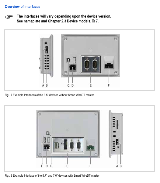
2. Interface configuration and wiring
XV-102 provides rich industrial interfaces, supporting multi protocol communication and expansion. The core interface parameters are as follows:
Interface type specifications and functional wiring requirements
Power interface 24V DC SELV (safe ultra-low voltage), voltage range 19.2-30V DC, maximum power consumption of 5W for 3.5-inch, maximum 9.5W for 5.7/7.0-inch, using Phoenix MSTB 2.5/3-ST-5.08 connector (built-in); XT-FIL-1/2 anti-interference filter needs to be installed (for maritime/EMC B-level scenarios)
Ethernet 100Base TX/10Base-T (RJ45), supporting LED status indication (ACT flashing=data transmission, LINK constantly on=network connection) using shielded twisted pair (STP); Cross wires are used between devices, and straight wires are used to connect to switches; Maximum length 100m
RS232 (system port) 9-pin D-Sub male, non isolated, supports up to 115200 bit/s (within 2.5m) with shielded cable; The cable length is negatively correlated with the baud rate (e.g. ≤ 9600 bit/s at 30m); The GND terminal must be connected
RS485 9-pin D-Sub male, non isolated, supports 32 slave stations, and requires 120 Ω terminal resistors at both ends of the bus using shielded twisted pair cables; Maximum length 500m (0.75mm ² wire diameter); The GND terminal must be connected
CAN 9-pin D-Sub male head, non isolated, compliant with CiA standard, supports 32 shielded twisted pair cables with characteristic impedance of 120 Ω for slave stations; Maximum length of 5000m (at 10 kbit/s); Terminal resistors are required at both ends of the bus
Profibus 9-pin D-Sub female head, non isolated, up to 1.5 Mbit/s (within 200m) using Profibus Class A shielded twisted pair (impedance 150 Ω); Terminal resistors are required at both ends of the bus; 5V pin prohibits external power supply
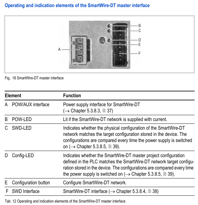
SmartWire DT Master 8-pin interface (SWD)+POW/AUX power interface, non isolated, supports up to 99 SWD modules with dedicated SWD cables (such as SWD4-100LF8-24); UAUX requires external 2A circuit breaker (UL standard) or 3A fuse (DIN standard)
USB USB 2.0(Device Type B/Host Type A), Non isolated shielded USB cable; Maximum length of 5m; Host interface supports external devices such as USB drives
Operation and Maintenance
1. Basic operations
Power on and off: No physical switch, automatically boots when powered on, shuts down when powered off; For the first startup, please refer to the "Windows CE System Instructions" (MN05010007Z) to configure system parameters and install applications.
SD card operation: Only plug and unplug when the device is powered off; Used to store project files or data, avoiding frequent writes (limited lifespan); Power off is prohibited during reading and writing.
Touch calibration: It has been calibrated at the factory. If there is an abnormal response, it needs to be recalibrated using system tools (refer to the "Windows CE System Instructions"); Operate only with fingers or a dedicated stylus, and avoid touching with sharp objects (to prevent damage to the resistive screen).
2. Maintenance and troubleshooting
(1) Daily maintenance
Cleaning: Use a clean, soft, and damp cloth to wipe the resistance screen. For stubborn stains, dip a small amount of detergent in it; Do not use sharp tools, corrosive solvents, or liquids to infiltrate the equipment.
Battery maintenance: Built in CR2032 lithium battery (3V/190mAh), non replaceable, can maintain real-time clock for about 10 years after power failure.
Repair restriction: Self opening repair is prohibited. Contact Eaton authorized repair center or supplier.
(2) Common fault handling
Possible causes and solutions for the fault phenomenon
The device cannot start and the power supply is not properly connected or the voltage is abnormal. Check the 24V DC power supply wiring; Confirm that the voltage is within the range of 19.2-30V DC
Touch screen unresponsive/response deviation touch screen not calibrated; Install the bracket too tightly and recalibrate the touch screen; Loosen the top wire of the bracket (torque ≤ 0.1 Nm)
Display screen black, backlight not activated or malfunction check, backlight settings in visualization software; Fault needs to be returned to the factory for repair
Communication interruption (such as Ethernet/CAN) cable not connected properly; Terminal resistor missing; Interference check cable wiring; Confirm the connection of 120 Ω terminal resistors at both ends of the bus; Install anti-interference filter or magnetic ring
Technical parameters and compliance certification
1. Core technical parameters
Parameter category specification
Display performance of 3.5 inches (QVGA/32 grayscale/64K color), 5.7 inches (VGA/64K color), 7.0 inches (WVGA/64K color); The lifespan of LED backlight is about 40000 hours, and the brightness can be adjusted by software
System configuration: 32-bit RISC processor (400MHz); 64MB DRAM + 64MB NAND Flash; Some models include 125KB NVRAM
Protection level: IP65 on the front (requires correct installation of brackets), IP20 on the back
Environmental adaptability: working temperature 0-50 ℃, storage temperature -20-60 ℃; Relative humidity ranging from 10% to 95% (without condensation); Anti vibration (5-150Hz, 2g), anti impact (15g/11ms)
Power supply characteristics: 24V DC SELV, with reverse polarity protection and built-in fuses; Start impulse current 1.5A/2s
2. Compliance certification
Safety and EMC: Compliant with UL 508 (Industrial Control Equipment), UL 60950 (Information Technology Equipment), CE (EMC Directive 2014/30/EU); ATEX 2014/34/EU (Zone 22, 3D explosive environment).
Industry certification: DNV GL classification certification (TAA00000NC), suitable for maritime scenarios; Compliant with IEC/EN 61131-2 (Requirements for PLC Equipment) and EN 50178 (Electronic Equipment for Power Installation).
Storage, transportation, and disposal
Storage: ambient temperature -20-60 ℃, relative humidity 10% -95% (no condensation); Avoid direct sunlight, vibration, and chemical corrosion.
Transportation: Use original packaging to avoid impact and compression; The transportation environment must meet the storage conditions, and upon arrival, inspect for any transportation damage.
Disposal: The equipment contains lithium batteries (CR2032, containing 1.2-dimethoxyethane), which need to be professionally disposed of according to local environmental standards or returned to Eaton for disposal; The packaging materials (cardboard, PE bags) are recyclable.
- YOKOGAWA
- Reliance
- ADVANCED
- SEW
- ProSoft
- WATLOW
- Kongsberg
- FANUC
- VSD
- DCS
- PLC
- man-machine
- Covid-19
- Energy and Gender
- Energy Access
- Renewable Integration
- Energy Subsidies
- Energy and Water
- Net zero emission
- Energy Security
- Critical Minerals
- A-B
- petroleum
- Mine scale
- Sewage treatment
- cement
- architecture
- Industrial information
- New energy
- Automobile market
- electricity
- Construction site
- HIMA
- ABB
- Rockwell
- Schneider Modicon
- Siemens
- xYCOM
- Yaskawa
- Woodward
- BOSCH Rexroth
- MOOG
- General Electric
- American NI
- Rolls-Royce
- CTI
- Honeywell
- EMERSON
- MAN
- GE
- TRICONEX
- Control Wave
- ALSTOM
- AMAT
- STUDER
- KONGSBERG
- MOTOROLA
- DANAHER MOTION
- Bentley
- Galil
- EATON
- MOLEX
- Triconex
- DEIF
- B&W
- ZYGO
- Aerotech
- DANFOSS
- KOLLMORGEN
- Beijer
- Endress+Hauser
- schneider
- Foxboro
- KB
- REXROTH
- YAMAHA
- Johnson
- Westinghouse
- WAGO
- TOSHIBA
- TEKTRONIX
- BENDER
- BMCM
- SMC
- HITACHI
- HIRSCHMANN
- XP POWER
- Baldor
- Meggitt
- SHINKAWA
- Other Brands
- UniOP
- KUKA
- IBA
- Beckhoff
-
ADLINK PCI-7433 - switch value acquisition card Isolated Digital Input Card
-
ADLINK PCI-9112 - 51-12252-0D20 Multi-Function Data Acquisition Card
-
ADLINK NUPRO-A301 REV:1.4 - industrial control motherboard PICMG Full-Size SBC
-
ADLINK 51-18502-0A10 - Frame Grabber Image Acquisition Interface Card
-
ADLINK PCI-7296 - 51-12009-0A50 PCB-I-E-925=6DX1 96-CH Parallel Digital I/O Board
-
ADLINK PCI-8132 GP A2 - Motion Control Card 2-Axis Servo & Stepper Controller
-
ADLINK PCI-7442 - switch quantity card data acquisition card 64-CH Isolated Card
-
ADLINK HPX-13S4 - baseboard PICMG 1.3 Passive Backplane Chassis Baseplate
-
ADLINK NuPRO-590 / NTC-567-ZM-F36 - Single Board Computer PCB-I-E-1853=9L21 Half-Size SBC
-
ADLINK PCIe-8332 - 16-axis plate Motion Control Hardware Card
-
ADLINK NuPRO-775 REV.B1 - motherboard Pentium 4 Full-Size PICMG SBC
-
ADLINK PXI-3920 - Embedded Controller 3U PXI cPCI System Intelligence Board
-
ADLINK PCI-8134 - driver card motion control card 4-Axis Controller Board
-
ADLINK HSL-DI32-M-N-011 / HSL-TB32-M-DIN - Digital Input & Base Module PLC Distributed I/O System
-
ADLINK PCI-6216V-206 / PCI-208V 009 - 16 CH 16bit analog output card
-
ADLINK NuPro-E330 - 51-41805-0A20 PCB Single Board Computer Host Board
-
ADLINK PCI-1622C - Card 8-Port RS-232/422/485 PCI Serial Communication Board
-
ADLINK PCIe-7432 - 51-18402-0A10 Carte PCIe Avec Plage D'Entrée Élevée Isolated DIO Card
-
ADLINK PCI-7250 - PCI Acquisition Card 8-CH Relay Output Isolated DI Card
-
ADLINK PCI-7230 - 32-CH Isolated Digital I/O Card
-
ADLINK PCI-8164 - PCB 4-Axis Motion Controller Card
-
ADLINK PCI-7854 - Collection card High-Speed Link Distributed Motion Controller
-
ADLINK NuPRO-935A/LV - industrial control computer motherboard Full-Size PICMG SBC
-
ADLINK IMB-M40H - motherboard IH61-AA4 1155 LGA1155 Micro-ATX Mainboard
-
ADLINK PCI-7248 - Linhua 51-12006-0A40 48-CH Parallel Digital I/O Card
-
ADLINK HPCI-14S12U - Linhua industrial computer baseboard Passive Backplane
-
ADLINK PCI-8132 Rev.A2 - 2-Axis Servo & Stepper Motion Controller Card
-
ADLINK ACL-8111 - ISA card Multi-Function DAQ Card
-
ADLINK ACL-8111 - ISA card Multi-Function Data Acquisition Board
-
ADLINK PCI-7200 REV.A3 - Digital I/O card 12MB/s High-Speed Parallel Digital I/O
-
ADLINK PCI-7296 REV.A3 - 96-CH High-Density Opto-Isolated DIO Card
-
ADLINK PCI-7434 - 64-CH Isolated Digital Output Card
-
ADLINK M-342 - atx motherboard Industrial PC Mainboard
-
ADLINK NuPRO-935ADV (A) 1.9 - CPU Board Intel Core 2 Quad CPU Q9500 2.83GHz PICMG Board
-
ADLINK NUPRO-935A/DV - motherboard dual network port 51-41802-0A10 CPU Board
-
ADLINK PCI-RTV24 - image capture card Analog Video Frame Grabber Board
-
ADLINK HPX-13S4 - device baseboard PICMG 1.3 Passive Backplane Chassis Baseplate
-
ADLINK PCI-8134A - control card 4-Axis Motion Controller Card
-
ADLINK ACL-7130 REV. B2 - industrial control capture card Isolated Digital I/O Board
-
ADLINK EBP-13E2 - Industrial Backplane Board Passive Backplane Baseboard
-
ADLINK NuPRO-935ADV (A) 1.9 - CPU Board Intel Core 2 Quad CPU Q9500 2.83GHz PICMG SBC
-
ADLINK PCI-8134A - motion control card 4-Axis Pulse-Train Controller Card
-
ADLINK PCI-9112 REV A.1 - Multi Function DA&C Board Data Acquisition Card
-
ADLINK 51-12001-0C20 - Circuit Board Multi-Function Data Acquisition Hardware
-
ADLINK PCI-7300A - 80-CH High-Speed Digital I/O Card
-
ADLINK PCI-7230 - 16-CH Isolated Digital Input Output Card
-
ADLINK DIN-814-GP - motion control module Interface Terminal Block
-
ADLINK NUPRO-A40H - 51-41807-1A20 Industrial Control Motherboard LGA1155
-
ADLINK PCI-7433 rev A2 - Isolated Digital Input Card
-
ADLINK NuPRO-780 - Pentium III 800 512 MB SBC NuPRO780 51-41309-0B2 Single Board Computer
-
ADLINK PCI-7853 / PCI-7854 - Acquisition card High-Speed Link Control Card
-
ADLINK NUPRO-852 / NUPRO-852LV - Industrial motherboard Full-Size PICMG CPU Board
-
ADLINK NuPRO-842LV/P - 51-41360-0B30 Industrial Motherboard Half-Size PICMG SBC
-
ADLINK PCI-FIW64 - 4/2 Channel IEEE1394B Image Capture Card Frame Grabber
-
ADLINK PCI-7851 Rev A1.1 - HSL system card High-Speed Link Master Controller
-
ADLINK PCI-7230 - 51-12003-0A50 card 32-CH Isolated Digital I/O Card
-
ADLINK NuPRO-841REV:1.0 - Industrial CPU Board Mainboard
-
ADLINK NuPRO-841 REV:1.0 - motherboard Industrial Control PC Mainboard
-
ADLINK PCI-8256 - 8-Axis Advanced Motion Control PCI Board
-
ADLINK PCI-6S / PCI6S - Backplane 6-Slot Passive Backplane Board
-
ADLINK PCI-7234 REV B3 - 32-CH Isolated Digital Output PCI Card
-
ADLINK PCI-8213 - HannStar MV-4 51-45003-0b4 Board
-
ADLINK PCI-7233 - 51-12004-0a20 board PCI7233 32-CH Isolated Digital Input Card
-
ADLINK PCI-7851 - 006 51-24003-0B20 High-Speed Link Master Motion Control Card
-
ADLINK PCI-7432 - 64-CH Isolated Digital I/O PCI Cards
-
ADLINK LPCI-3488 - Card Low Profile IEEE-488 GPIB Interface Card
-
ADLINK HPCI14S REV.B1 - industrial control computer base plate Passive Backplane
-
ADLINK NEON-1020 - Industrial camera Smart Camera Vision System
-
ADLINK PCI-7432 - Isolated Digital I/O PCI Card 64-CH
-
ADLINK Pcm-7250+ - 8-Ch Relay Outputs & 8-Ch Isolated DI Module PC/104
-
ADLINK CPCI-7841 - DUAL-PORT ISOLATED CAN INTERFACE CARD CompactPCI
-
ADLINK PCI-3488 / PCI-GPIB - PCI IEEE-488 GPIB Interface Card
-
ADLINK PCI-1711U - Card Multi-Function Data Acquisition Board
-
ADLINK NUPRO-A301 - REV:1.1 1.2 1.4 PICMG Full-Size Single Board Computer
-
Adlink DIN-50S-01 - PLOTECH 51-14024-0A40 50-pin Wiring Terminal Board
-
Chroma 52962 / 58183 - PXI Optical Spectrometer carrier adapter Card
-
ADLINK PCI-6208V - PCI DATA ACQUISITION & RECORDING CARD 8-CH Analog Output
-
ADLINK HSL-DI32-DB-N - Industrial Control Board Distributed Digital Input Module
-
ADLINK HSL-AO4-U - 4-CH HIGH SPEED LINK ANALOG OUTPUT MODULE Distributed I/O
-
ADLINK PCI-7396 - 0050 GP 51-12012-0B20 96-CH High-Speed Digital I/O Card
-
ADLINK NUPRO-935A/DV - 51-41802-0A10 motherboard Industrial CPU Single Board Computer
-
ADLINK PCI-9111 DG - Industrial Acquisition Card Multi-Function DAQ Card
-
ADLINK NuPRO-E315 - industrial computer motherboard Intel Atom SHB SBC
-
ADLINK NUPRO-406 REV:B1 - Industrial Control Motherboard Full-Size PICMG CPU Board
-
ADLINK NuPRO-E330 - motherboard Industrial Control System Host Board PICMG 1.3
-
ADLINK ACL-6128A 103 - 51-11002-1A4 2-CH Isolated Analog Output Card
-
XTRAMUS cPS-H325/AC - POWER SUPPLY NUSTREAMS 600 NETWORK TESTING EQUIPMENT Power Module
-
ADLINK DIN-814P-A4 - 51-14056-0A10 Terminal Block Motion Control Breakout Board
-
ADLINK TB-24P/24-01 - 24-Channel Card Terminal Breakout Board
-
ADLINK PCI-7251 - 51-12008-0A30 PCI7251 8-CH Relay Output Isolated Digital Input Card
-
ADLINK HSL-TB64-DIN REV A1 / HSL-DO32-DB-N - 2ea Board Breakout Terminal Board Distributed I/O Module
-
ADLINK NuPRO-865 REV 3.0 - industrial computer motherboard Full-Size PICMG SBC
-
ADLINK NUPRO-A40H - motherboard 51-41807-1A30 OSP H61 Industrial PC Mainboard
-
ADLINK LPCI-3488A - PCI Card 51-12801-0A30 GPIB Interface Card
-
ADLINK DIN-825-4P0 - 51-14085-0A30 Terminal Printed Circuit Board Breakout Block
-
ADLINK IMB-T10/D2550 V - MOTHER BOARD 80-PXG160-A1A01 IMB-T10-M2G-S32G Industrial Mainboard
-
ADLINK PCI-8144N - Motion Control card Stepper Motor Controller
-
ADLINK PCI-7433 - Digital acquisition card Isolated Digital Input Card
-
ADLINK PCI-9112 DG - Data Acquisition card 51-12252-0D20 Multi-Function DAQ
-
ADLINK IMB-M40H - motherboard IH61-AA4 1155 LGA1155 Micro-ATX Mainboard
-
ADLINK TB-24P/24-01 - Carte 24 voies Terminal Breakout Board Connector Module
-
ADLINK HSL-D16DO16-M-NN - Distributed Discrete Input Output I/O Module
-
ADLINK PCI-7248 - PCI CARD 51-12006-0A40 48-CH Parallel Digital I/O Board
-
ADLINK HSL-DI32-DB-N - Industrial Control Board Distributed I/O Digital Input Module
-
ADLINK PCI-7433 - Pci 7433 Isolated Digital Input Card
-
ADLINK PCI-6208V - 008 Data acquisition card 8-CH Analog Output Card
-
ADLINK IH61-AA4 - industrial motherboard LGA1155 Micro-ATX Mainboard
-
ADLINK PXI-3920 - PXI 3U cPCI Industrial Controller Embedded System CPU Board
-
ADLINK PCI-6308 - Analog Output DAQ Card Isolated Voltage Output Card
-
ADLINK PCI-7200 - data acquisition card REV.A3 High-Speed Parallel DIO Card
-
ADLINK NuPRO-E315 - Industrial Control Computer Motherboard PICMG 1.3 SHB SBC
-
ADLINK PCI-1610C - Card 4-Port Isolated RS-232 PCI Serial Communication Card
-
ADLINK PCI-1716 - Card High-Resolution Multi-Function DAQ Card
-
ADLINK MI-965 - Industrial Mini-ITX Motherboard CPU Board
-
ADLINK PCI-1610A - Card 4-Port RS-232 PCI Serial Communication Card
-
ADLINK cBP-3208/3208R - CPCI Board 3U 8-Slot CompactPCI Backplane
-
ADLINK PCI-8134A - 51-12421-0A10 4-Axis Motion Controller Card
-
ADLINK PCI-8164 - Motion Control Card 4-Axis Advanced Controller Card
-
ADLINK NUPRO-935A/DV - motherboard dual network port 51-41802-0A10 CPU Board
-
ADLINK PCI-7248 - 51-12006-0A40 acquisition card 48-CH Parallel DIO Card
-
ADLINK PCI-7443 - 51-12022-0A10 BOARD 128-CH Isolated Digital Input Card
-
ADLINK DIN-825-GP4 - Terminal Block Interface Board Breakout Module
-
ADLINK PCI-7248 - Card 48-CH Parallel Digital I/O Card
-
ADLINK NUPRO-865 REV :3.0 - industrial motherboard Intel Pentium 4 CPU Board
-
ADLINK PCI-9113A - Isolated Analog Input Data Acquisition Card
-
ADLINK HPCI-8S4 - REV.B2 Industrial Control Base Plate Passive Backplane
-
ADLINK M-342 - atx motherboard Industrial PC Mainboard
-
ADLINK PCI-RTV24 - image capture card Analog Video Frame Grabber Board

K-JIANG

Add: Jimei North Road, Jimei District, Xiamen, Fujian, China
Tell:+86-15305925923