
K-WANG


YOKOGAWA YS100 series instrument
YOKOGAWA YS100 series instrument
The YS100 series instruments (including YS150/YS170/YS131/YS135/YS136 models) support RS-485 (option code/A31) and DCS-LCS (option code/A32) communication functions. The former can be interconnected with multiple monitoring computers (up to 16 units, communication distance ≤ 1200m), while the latter can be connected to the Yokogawa CENTUM-XL/μ XL DCS system (up to 24 units/EFCS); The core communication parameters include baud rate of 1200-9600bps, half duplex mode, ASCII 8-bit encoding, support for data read and write (DG/DP commands), watchdog timer settings, and other functions. The parameters need to be configured through the front-end panel to adapt to the monitoring and operation requirements in industrial process control, while providing a comprehensive error handling mechanism and programming examples.
Core communication specifications
(1) RS-485 communication specifications
Category specific parameters
Communication interface RS-485 five signals: SD (A), SD (B), RD (A), RD (B), SG (signal ground)
Communication protocol without protocol (command response format), asynchronous operation
Transmission parameter baud rate: 1200/2400/4800/9600bps; Stop position: 1/2 position; Parity check: None/Odd/Even
Data format ASCII 8-bit encoding, single block structure, maximum block length of 220 bytes (including CR/LF)
Up to 16 instruments can be connected (multi station connection), with a communication distance of ≤ 1200m
Wiring requirements recommend shielded twisted pair cables (0.5-1.25mm ²), supporting 2-wire/4-wire wiring, with 120 Ω± 1% terminal resistors at both ends
(2) DCS-LCS Communication Specification
Category specific parameters
Adaptation System Yokogawa Distributed Control System (CENTUM-XL, μ XL)
The connection method is to connect the LCS circuit communication card to the DCS on-site control unit
The maximum connection capacity is 8 instruments/LCS cards, 3 LCS cards/MFCU, 24 instruments/MFCU, and 120 instruments/EFCS
Wiring requirements: KS4 cable (maximum length 100m), SCCD shielded twisted pair cable
The core function of YS100 is registered as an internal instrument of DCS, which can be monitored, operated, and parameter set through the DCS operator station
Installation and parameter configuration
(1) Terminal allocation
Terminal number RS-485 communication function DCS-LCS communication function
14 Signal Ground (SG) LCS+, LCS-
Send Data A (SD (A))-
16 Send Data B (SD (B))-
17 Receive Data A (RD (A))-
18 Receive Data B (RD (B))-
FG (GND) shielding layer shielding layer
(2) Parameter configuration (front-end panel CONFIG1 menu)
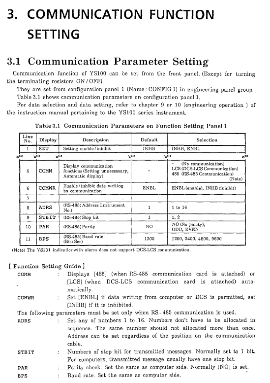
Configuration item function description default value optional range
SET configuration enable/disable INHB INHB (disable), ENBL (enable)
COMM communication function display -485 (RS-485), LCS (DCS-LCS)
COMWR communication write enable ENBL ENBL (allowed), INHB (prohibited)
ADRS RS-485 instrument address 1-16
STBIT RS-485 stop bits 1, 2
PAR RS-485 parity check NO NO, ODD odd, EVENT even
BPS RS-485 baud rates 1200, 2400, 4800, 9600bps
(3) Computer mode settings
Mode Type Applicable Model Function Description
SPC mode YS150/YS170 monitoring system sends set values
DDC mode YS150/YS170 monitoring system sends operation signals
Switch between backup mode YS150/YS170 in case of monitoring system failure (BUA automatic/BUM manual)
Communication functions and commands
(1) RS-485 core command
Example of Command Function Format
DG (Data Reading) reads instrument parameters (PV/SV/MV, etc.) and sends: DG 02 03 PV1 SV1 MV1 [CR] [LF]; Response: DG 02 03 50.0 30.0 65.5 [CR] [LF]
DP (Data Write) sets instrument parameters (alarm values/set values, etc.) and sends: DP 02 03 PH1 98.0 PL1 5.0 [CR] [LF]; Response: DP 02 03 98.0 5.0 [CR] [LF]
Set timeout time in WDT (watchdog setting) DDC/SPC mode and send: WDT 01 0060 [CR] [LF]; Response: WDT 01 0060 [CR] [LF]
(2) Communication data type (core commonly used)
Data Type Name Applicable Model Range Read/Write Permissions
PV1/PV2 process variable series -6.3~106.3% read-only
SV1/SV2 set values YS150/YS170/YS135-6.3~106.3% can be written (specific mode)
MV1/MV2 operation variables YS150/YS170/YS136-6.3~106.3% writable (specific mode)
PH1/PL1 high and low limit alarm set values for the entire series -6.3~106.3% can be written
PRCA process alarm status series 8-bit binary (0=normal/1=fault) read-only
LS1/LS2 operating modes YS150/YS170 MAN/OUT/CAS/SPC/DDC can be written
(3) DCS-LCS communication correspondence
YS100 DCS Instrument Model Core Monitored Parameters
YS150 SLPC PV, SV, MV, P (proportional band), I (integral time), D (derivative time)
YS170 SLPC PV、SV、MV、 Program control parameters, alarm status
YS135 SMST-111 PV、SV、 High and low limit alarm setting values
YS136 SMST-121 PV、MV、 Upper and lower limits of manipulated variables
Error Handling and Programming Examples
(1) Common types of errors and their handling
Measures for handling error type phenomena
Communication parameters do not match, instrument does not respond, unified computer and instrument baud rate, parity check and other parameters
Address error: The instrument is unresponsive. Please confirm the instrument address (1-16) to avoid duplicate allocation
The response message is too long and returns an error code @ 100. Reduce the amount of data read in a single attempt and ensure that the message is ≤ 220 bytes
Return the corresponding error code for syntax errors (such as @ 011=invalid command). Check the command format, parameter names, and data format
(2) Programming Example
Provide an IBM-PC BASIC program example for reading data from YS100 instrument PV1, SV1, and MV1 at address 01. The core steps include port configuration, command sending, response receiving, and display.
User Program Example (YS170 Proportional Controller)
Proportional control is achieved through DCS-LCS communication, using BS (corresponding to P1 parameter) to set the proportional coefficient, X2 as the cascaded input value, Y4/Y5 as the communication register feedback intermediate calculation result, and finally outputting CSV1 as the set value to drive the control loop.

- YOKOGAWA
- Reliance
- ADVANCED
- SEW
- ProSoft
- WATLOW
- Kongsberg
- FANUC
- VSD
- DCS
- PLC
- man-machine
- Covid-19
- Energy and Gender
- Energy Access
- Renewable Integration
- Energy Subsidies
- Energy and Water
- Net zero emission
- Energy Security
- Critical Minerals
- A-B
- petroleum
- Mine scale
- Sewage treatment
- cement
- architecture
- Industrial information
- New energy
- Automobile market
- electricity
- Construction site
- HIMA
- ABB
- Rockwell
- Schneider Modicon
- Siemens
- xYCOM
- Yaskawa
- Woodward
- BOSCH Rexroth
- MOOG
- General Electric
- American NI
- Rolls-Royce
- CTI
- Honeywell
- EMERSON
- MAN
- GE
- TRICONEX
- Control Wave
- ALSTOM
- AMAT
- STUDER
- KONGSBERG
- MOTOROLA
- DANAHER MOTION
- Bentley
- Galil
- EATON
- MOLEX
- Triconex
- DEIF
- B&W
- ZYGO
- Aerotech
- DANFOSS
- KOLLMORGEN
- Beijer
- Endress+Hauser
- schneider
- Foxboro
- KB
- REXROTH
- YAMAHA
- Johnson
- Westinghouse
- WAGO
- TOSHIBA
- TEKTRONIX
- BENDER
- BMCM
- SMC
- HITACHI
- HIRSCHMANN
- XP POWER
- Baldor
- Meggitt
- SHINKAWA
- Other Brands
- UniOP
- KUKA
- IBA
- Beckhoff
- ADLINK
-
Beckhoff CX1100-0910 - Power Supply Module
-
Beckhoff C5210-0010 - Communication Module C5210
-
BECKHOFF KL1352 - Bus Terminal SET OF 2 FREE FAST SHIP
-
Beckhoff EL3058 - 8 x analog input single ended 4...20mA 85惟 shunt 12bit
-
Beckoff CX1100-0920 - UPS Module 24VDC (US SELLER) * *
-
BECKHOFF C6920-0000 - C69200000 PLC Moudule
-
Beckhoff CX5120-0115 - CPU controller module CX5120-0115
-
Unknown 15F5C1E-Y50A - Of Frequency Converters
-
Beckhoff AX5118-0000-0200 - Servo Drive HTP0
-
BECKHOFF AX5106-0000-0200 - Servo Drive
-
Beckhoff CX5240-0175 - Module (free) #U2327D YG
-
Beckhoff CP6607-0001-0000 - Compact PC Panel Economy Installation Operator 5,7 "
-
Beckhoff EP3744-0041 - 2022 EP37440041 Module
-
Beckhoff CP6209-0001-0020 - 6.5" PC Touch Screen Control Panel 24VDC
-
Beckhoff CX9020-0111 - /U900 +8x+2xEL3121+1x EL9410+3xEL1008+1x EL2008 Set
-
Beckhoff C6525-1030-0050 - Industrial PC
-
Beckoff CX1100-0920 - UPS Module 24VDC (US SELLER)
-
Beckhoff CX5010-0120 - CX5010 Processor Intel Atom Z510 B24
-
Siemens 6FC5203-0AF04-1BA1 - Operation Panel
-
Beckhoff CX5230-0175 - / 000029724 Embedded PC / Industrial PC on Rail
-
Beckhoff CP3916-0000 - industrielles Anzeige- und Bedienterminal
-
BECKHOFF CX1500-M310 - CX1000-N000 CX1000-0011 CX1000-C00L CX1100-0002 PLC Module
-
Beckhoff EL1872 - 16-channel digital input terminal
-
BECKHOFF EP2318-0001 - module
-
Beckhoff CX9020-0110 - Basic CPU Module
-
Beckhoff EL2564 - EtherCAT Terminal, 4-channel LED output, 5鈥?8VDC, 4A, RGBW
-
Beckhoff CX5130-0155 - /000105637 Automation Embedded PC
-
B&R 400 - Power Control Panel Rev D0 24 VDC
-
Beckhoff CX2020-0155 - module
-
Beckhoff CX9020-0115 - PLC Module
-
BECKHOFF EL6695 - PLC EL 6695
-
BECKHOFF EL7047 - PLC Modules
-
Beckhoff CX1000-0012 - Control HW 2.2 + CX1500-M310 + CX1000-C00L + CX1100-0002+
-
Beckhoff C6920-1039-0030 - control cabinet industrial PC CPU Celeron 1.90 GHz, 2 cores
-
BECKHOFF CX1100-0910 - PLC Module#
-
Beckhoff IL2301-B318-0000 - Coupler Box 4 Channel Digital Input |
-
Beckhoff CX7080 - Module
-
Beckhoff C6930-0060 - Industrial PC
-
Beckhoff CP7902-1060-0000 - Touchscreen 15 " CP7902
-
beckhoff CX9020-0111 - Controller module or UPS
-
Beckhoff CX8091 - PLC Module CX8091
-
Beckhoff C6640-1008-0030 - Control Cabinet Industrial PC
-
BECKHOFF CX1100-0920 - module
-
Beckhoff C9900-M921 - see pictures
-
BECKHOFF CP6829-0001-0000 - Touch Panel
-
BECKHOFF C6930-0060 - Industrial Computer
-
BECKHOFF CX8050 - PLC module
-
Beckhoff CP6202-0021-0020 - Touch Screen #
-
BECKHOFF AM3031-0C20-0000 - SERVO MOTOR
-
Unknown BCH1302N11A1C - Servo motor
-
Beckhoff EL2502 - 2-channel pulse width output terminal
-
Beckhoff EL6731 - Profibus Master / *Rev: 0025
-
Beckhoff CP3918-0010 - Control Panel
-
BECKHOFF CP2915-0010 - [24 MONTH WARRANTY] Control Panel
-
Beckhoff AX5203-0000-0202 - Servo Drive
-
Schneider TSXDSY64T2K - PLC OUTPUT MODULE
-
Beckhoff EP4174-0002 - Module-
-
Beckhoff IL2302-B318-0000 - Profibus Box
-
Beckhoff CP6709-0001-0000 - Touchpanel
-
BECKHOFF CX2030-0123 - Controller
-
Beckhoff CX9020-0111 - Processor Module
-
Beckhoff CX1020-0000 - CX Basic CPU Module
-
Beckhoff AX2003-AS - Servo Drive HTP0
-
Beckhoff C6240-1052-0040 - 4-086-06-3073 Industrial Computer CB1052-0003
-
Beckhoff EL1918 - 8 xTwinSAFE Input
-
Beckhoff AM8072-0R20-0000 - Servomotor
-
BECKHOFF AM8021-1B21-0000 - servo motor #T882 YS
-
Beckhoff EL6224 - 4 X Terminal IO-LINK
-
Beckhoff CX5140-0135 - embedded PC with Intel Atom processor 4 GB HW 3.6
-
Beckhoff CP7201-1000-0000 - Panel PC #
-
Beckhoff CX5130-0121 - Embedded-PC 4GB CPU Module HW 2.5 Industrial PC
-
Beckhoff AM8022-0D41-1002 - Servomotor
-
BECKHOFF CX2030-0130 - Module
-
BECKHOFF EL1872 - 16-channel digital input terminal
-
Unknown GXMMW.A203P33 - 1pc encoder
-
Beckhoff EL6631-0000 - EtherCAT Terminal 2-Port EL 6631
-
BECKHOFF C6925-0030 - Industrial Computer
-
Beckhoff CX8190 - A Module
-
BECKHOFF CX2040-0135 - CX2040-0135/000000927 CPU BASE MODULE i7 2715QE 2.1GHz --
-
BECKHOFF KL6023-0000 - Wireless adapter
-
Saia Burgess PCD7.F700 - PCD7F700 Communication Module
-
Beckhoff CX5130-0112 - CPU Module
-
BECKHOFF CX1020-N010 - CX1020-N000 CX1020-0111 CX1100-0004 EL2008 EL3064 EL4004
-
Beckhoff EP1819-0021 - A Module
-
Beckhoff CX2030-0120 - / 4gb with CX2100 0004
-
B&R X20-XC-0292 - Automation Powerlink Ethernet Bus Controller Module
-
Beckhoff BK3110 - One PLC Module
-
BECKHOFF KL3222 - PLC Module
-
BECKHOFF CX1500-M310 - CX1000-N000 CX1000-0011 CX1000-C00L CX1100-0002 PLC MODULE
-
Beckhoff CP3918-0010 - Control Panel
-
Beckhoff CX2030-0100-1002 - /4GB + CX2100 + CX2550 + CX2500-0060 + SSD
-
Beckhoff EP1816-0008 - PLC Module
-
Beckhoff CX5130-0112 - Module
-
Beckhoff Cx1500-m750 - CPU Hw: 1.4
-
BECKHOFF AX5112-0000-0200 - AX511200000200 Servo Driver
-
Beckhoff EL3751 - EtherCAT Terminal 1 Channel Analog Input Multifunction 24 Bit
-
Beckhoff CX1100-0002 - Power Supply Module
-
Beckhoff CP3916-1016-0010 - Control Panel
-
BECKHOFF CX9001-1101 - #NAME?
-
Beckhoff EP3174-0002 - EtherCAT Box Module
-
Beckhoff C6030-0070 - servo drive
-
Beckhoff CX2020-0120 - /4GB CPU, CX2100-0904, 3x EL6900, EL1904, 16GB Memory
-
BECKHOFF C6110 - BOX-PC 113608
-
BECKHOFF EK1914 - module #P
-
Beckhoff C6140 - Ipox IP-4GVI63 + CH7009A_DVI_TV + SIEMENS A5E00369843 + WD800AAJB
-
Beckhoff CX5020-0111 - controller Good quality
-
BECKHOFF C6015-0010 - / 6559380 ULTRA-COMPACT INDUSTRIAL PC ()
-
Beckhoff AX5203-0000-0200 - PLC module
-
Beckhoff EL2872 - 16-channel digital output terminal
-
BECKHOFF C3640-0000 - Panel Industrial PC 100/240VAC 128MB E0122L
-
Beckhoff CX8031 - Module
-
Beckhoff CX5020-0120-1002 - PLC module#
-
Beckhoff C6140 - M845B + SIEMENS A5E00369843 + C9900_A159_1 + AUTOMATA CAN PCI 1N
-
BECKHOFF AX5112-0000-0200 - Servo Drive*ie
-
B&R ECPA42-01 - Analog Output Module 4-Channel, +/- 10V Output Signal, 20mA Max
-
Beckhoff EL6631-0010 - PLC Module
-
BECKHOFF C6930-0070 - CONTROL CABINET INDUSTRIAL PC
-
BECKHOFF AX5112-0000-0200 - AX511200000200 Servo Driver
-
BECKHOFF EK9000 - Programmable Logic Controller Module EK9000 EK9000
-
BECKHOFF C6920-1028-0000 - Industrial computer
-
Beckhoff CX2030-0120 - controller Module
-
Beckhoff BX8000-0000 - Bus Terminal Controller HW 4.4
-
B&R 3NC154.60-2 - Positioning Module#
-
BECKHOFF CX1020-0122 - PLC module
-
Beckhoff AM3032-0D40-0000 - Servo Motor
-
BECKHOFF CX5020-0111 - CPU Module CX5020-0111
-
Beckhoff CB1051 - G5 Motherboard
-
BECKHOFF KL2641 - 1-channel relay output terminal

K-JIANG

Add: Jimei North Road, Jimei District, Xiamen, Fujian, China
Tell:+86-15305925923