
K-WANG


YASKAWA Z1000 series HVAC dedicated frequency converter
YASKAWA Z1000 series HVAC dedicated frequency converter
Applicable models:
200V level: 2.2~110kW (3~150HP);
400V level: 2.2~370kW (3~500HP);
Model identification: CIMR-ZU A series.
Core positioning: A practical guide for engineering and technical personnel, covering the entire process from parameter initialization, motor debugging to troubleshooting, supporting multiple modes such as V/f control and PM motor open-loop vector control, and adapting to the dynamic adjustment needs of HVAC systems.
Core functional framework
The document revolves around three core modules: parameter configuration, function implementation, debugging and maintenance. The core modules include parameter details, regular inspection and maintenance, and communication protocol configuration (BACnet/APOGEE FLN/Metasys N2/EMOBU/Modbus), forming a complete closed loop of "setup run monitoring maintenance".
Core parameter configuration (classified by functional modules)
1. Initialize parameters (Group A)
The core is used for initial driver settings, including basic configurations such as language, control mode, parameter reset, etc.
A1-00 (Language Selection): Supports English, Japanese, French, Spanish, Portuguese, and does not reset this parameter during initialization.
A1-02 (Control mode selection): 0 (Induction motor V/f control, speed range 1:40), 5 (PM motor open-loop vector control, speed range 1:20).
A1-03 (Parameter Initialization): Supports multiple initialization modes such as user-defined, 2-wire/3-wire control, HVAC dedicated, OEM bypass, etc., and automatically returns to 0 after reset.
A1-04/A1-05 (password setting): A1-05 hides the parameter setting password, A1-04 unlocks by entering the password, and restricts the modification permission of core parameters (such as A1-01~A1-03).
2. Application Function Parameters (Group B)
Focus on core application functions such as operating mode, braking, speed search, PI control, etc., and adapt to HVAC load characteristics.
(1) Operation mode selection (b1 group)
B1-01 (AUTO mode frequency source): Supports four input methods: HOA keyboard, analog terminal, communication, and tab.
B1-02 (AUTO mode operation command): Optional control terminals, communication, and tab triggers. Selecting 3 when no tab is installed will trigger the oPE05 error.
B1-03 (stop mode): 0 (slope stop), 1 (free stop), 2 (DC injection brake stop), 3 (free stop with delay).
(2) PI control (b5 group)
Specially designed for closed-loop control of pressure, flow, and temperature in HVAC systems, with core parameters:
B5-01 (PI function enabled): 0 (disabled), 1 (PI output directly as frequency command), 3 (PI output combined with frequency command).
B5-02/B5-03 (Proportional/Integral Parameters): Proportional gain of 0.00~25.00, integration time of 0.0~3600s, can suppress overshoot or accelerate response speed.
B5-12 (PI feedback loss detection): Supports low/high feedback detection, can set alarms, faults, or only output signals to avoid sensor failures causing system loss of control.
(3) Energy saving function (b8 group)
B8-01 (Energy saving control enable): When enabled, automatically optimize the motor operating voltage to improve light load efficiency. PM motors should be used with caution.
3. Motor parameters (Group E)
The core parameter configuration covering induction motors and PM motors directly affects control accuracy.
E1 group (V/f mode setting): E1-03 selects V/f curve (15 presets+1 customization), suitable for constant torque, variable torque (fan/pump), high starting torque and other scenarios.
E2 group (induction motor parameters): requires input of motor rated current (E2-01), rated slip (E2-02), no-load current (E2-03), etc., supporting automatic tuning and automatic acquisition.
E5 group (PM motor parameters): Only visible when A1-02=5, stator resistance (E5-05), d/q-axis inductance (E5-06/E5-07), induced voltage constant (E5-09/E5-24), etc. need to be set.
4. Protection function parameters (L group)
Comprehensively ensuring the safety of drivers, motors, and systems, with core components including:
Motor protection (L1 group): L1-01 selects overload protection type (general motor/PM motor), supports PTC thermistor connection (L1-03~L1-05) to detect motor temperature.
Power protection (L2 group): L2-01 is configured with instantaneous power failure response strategy, and L2-05 is set with undervoltage detection level (default 190V for 200V level, default 380V for 400V level).
Lock rotor protection (L3 group): Install lock rotor protection during acceleration, deceleration, and operation to avoid motor overload or overvoltage faults.
Fault restart (L5 group): L5-01 sets the number of automatic restarts (0-10 times), supports automatic recovery after overcurrent, overload, overvoltage and other faults, and the lifting application is disabled.
5. Terminal functional parameters (H group)
Configure digital/analog input/output terminals to achieve external signal interaction.
H1 group (digital input): 7-channel programmable terminals (S1~S7), supporting functions such as forward and reverse rotation, multi-stage speed, fault reset, emergency stop, etc., and can be configured with 2-wire/3-wire control logic.
H2 group (digital output): 3 relay outputs (M1-M2/M3-M4/M5-M6), which can map signals such as operating status, zero speed, fault, and consistent speed.
H3 group (analog input): 2 analog terminals (A1/A2), supporting 0~10V/4~20mA signals, configurable frequency command, PI feedback, torque detection level and other functions.
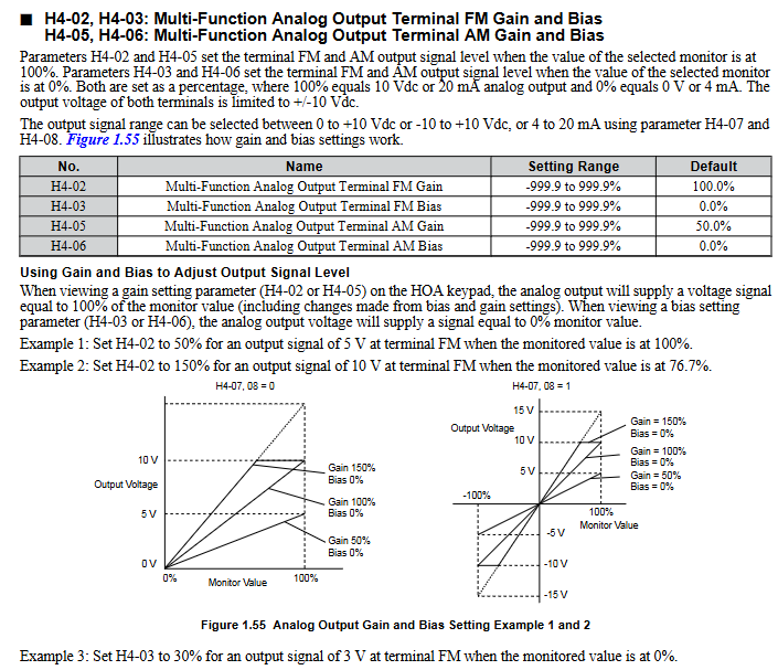
H4 group (analog output): 2 analog terminals (FM/AM), capable of outputting monitoring data such as frequency, current, power, etc., supporting gain/bias adjustment.
6. Communication parameters (H5/F6/F7 group)
Supports multiple industrial communication protocols and is compatible with building automation system integration.
Core protocols: BACnet, APOGEE FLN, Metasys N2, MEMOBU/Modbus;
Basic configuration: H5-01 (slave address), H5-02 (baud rate), H5-03 (checksum), which need to be unified with the upper computer;
Fault handling: F6-01 configuration communication fault driver behavior (shutdown/continue running/alarm).
Motor debugging (T group)
Obtain precise motor parameters through automatic tuning to ensure control performance.
1. Induction motor debugging (T1 group)
T1-01 selects tuning mode: 2 (static resistance detection), 3 (V/f energy-saving mode rotation tuning);
Pre input of motor rated power (T1-02), voltage (T1-03), current (T1-04) and other nameplate parameters is required, and after tuning, the E2 group parameters will be automatically updated.
2. PM motor debugging (T2 group)
T2-03 Select motor type (0=IPM motor, 1=SPM motor);
T2-18 starts tuning and automatically calibrates key parameters such as stator resistance, inductance, and induced voltage constant, ensuring that the motor is unloaded.
Monitoring parameters (U group)
Real time viewing of drive operation status, fault records, and maintenance information, core categories:
U1 group (operating status): output frequency (U1-02), output current (U1-03), DC bus voltage (U1-04), etc;
U2/U3 group (fault tracing): record parameter snapshots (such as current, frequency) and historical fault lists (up to multiple records can be stored) when faults occur;
U4 group (maintenance monitoring): cooling fan running time (U4-03), percentage of capacitor life (U4-05), pre charge relay life (U4-07), etc. If it is less than 20%, it needs to be replaced in advance;
U5 group (PI monitoring): PI set values, feedback values, output values, etc., facilitate closed-loop control optimization.
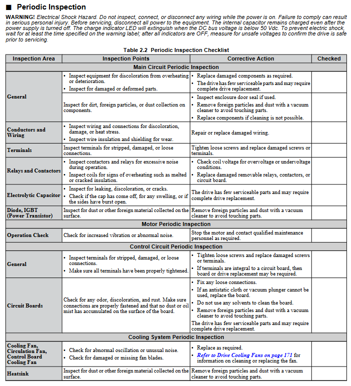
Regular inspection and maintenance
1. Safety regulations
After power failure, wait for the capacitor to discharge (DC bus voltage below 50V) before wiring or replacing components;
Do not remove the cover plate or touch the circuit board while it is powered on to avoid static electricity damaging the components.
2. Inspection cycle and content
(1) Daily inspection (daily)
Appearance: The driver/motor has no abnormal noise, odor, or vibration, and the cooling fan is running normally;
Display: No alarm code, stable parameters such as current and voltage;
Environment: Temperature (-10~+50 ℃), humidity (0~95% without condensation) meet the requirements, and there is no dust accumulation.
(2) Regular inspection (annually)
Electrical components: The wiring terminals are securely fastened, the insulation of the wires is not aged, the capacitors are not leaking or bulging;
Cooling system: The radiator is clean, the fan is not stuck, and the air duct is not blocked;
Function verification: No abnormal changes in parameters, protection functions (such as overload and overvoltage) triggered normally.
3. Replacement of vulnerable parts
Cooling fan: Replace it after running for 20000 hours or 5 years, and reset the o4-03 parameter after replacement;
HOA keyboard battery: The model is CR1220 lithium battery, with a lifespan of about 2 years. Replace it when "bAT" is displayed, and pay attention to the installation of the positive and negative poles;
Capacitors and relays: After 5-7 years of operation, the capacity/contact status needs to be checked, and if it is lower than 80% of the initial value, it should be replaced.
Communication Protocol Configuration (Core Protocol Summary)
1. MEMOBU/Modbus communication
Physical interface: RS-422/RS-485 (terminal R+/R -/S+/S -);
Core parameters: Slave address (H5-01:0~FFH), baud rate (H5-02:1200bps~115200bps), parity bit (H5-03: none/even/odd parity);
Function: Supports reading monitoring data, writing parameters, controlling start stop, and fault reset.
2. BACnet communication
Adapt to building automation systems and support BACnet MS/TP protocol;
Configuration parameters: F6-46 (baud rate), device object, analog input/output object mapping;
Function: Implement remote monitoring and control of the frequency converter by the upper computer, and support fault alarm uploading.
Compliance and Safety Tips
Safety level: Complies with UL 508C, CSA C22.2 No.14, CE LVD/EMC and other standards;
Prohibited scenarios: It is prohibited to use equipment that directly affects personal safety, such as medical, aviation, nuclear power, etc. The lifting application is disabled and automatically restarted due to malfunction;
Operation specifications: All wiring, parameter modification, and maintenance work must be carried out by authorized personnel, and the power-off discharge process must be strictly followed.
- YOKOGAWA
- Reliance
- ADVANCED
- SEW
- ProSoft
- WATLOW
- Kongsberg
- FANUC
- VSD
- DCS
- PLC
- man-machine
- Covid-19
- Energy and Gender
- Energy Access
- Renewable Integration
- Energy Subsidies
- Energy and Water
- Net zero emission
- Energy Security
- Critical Minerals
- A-B
- petroleum
- Mine scale
- Sewage treatment
- cement
- architecture
- Industrial information
- New energy
- Automobile market
- electricity
- Construction site
- HIMA
- ABB
- Rockwell
- Schneider Modicon
- Siemens
- xYCOM
- Yaskawa
- Woodward
- BOSCH Rexroth
- MOOG
- General Electric
- American NI
- Rolls-Royce
- CTI
- Honeywell
- EMERSON
- MAN
- GE
- TRICONEX
- Control Wave
- ALSTOM
- AMAT
- STUDER
- KONGSBERG
- MOTOROLA
- DANAHER MOTION
- Bentley
- Galil
- EATON
- MOLEX
- Triconex
- DEIF
- B&W
- ZYGO
- Aerotech
- DANFOSS
- KOLLMORGEN
- Beijer
- Endress+Hauser
- schneider
- Foxboro
- KB
- REXROTH
- YAMAHA
- Johnson
- Westinghouse
- WAGO
- TOSHIBA
- TEKTRONIX
- BENDER
- BMCM
- SMC
- HITACHI
- HIRSCHMANN
- XP POWER
- Baldor
- Meggitt
- SHINKAWA
- Other Brands
- UniOP
- KUKA
- IBA
- Beckhoff
-
LTI SC52.0040.0012.0000.0 - Servo Drive
-
Lti SC52.0040.0012.0000.0 - Servo Drive
-
Milton Industries LTI Tool By Milton LT1240 - 1/2" Drive Lugnut Remover
-
LTi Drives SO84.200.P030.0000.0-W - Servo Spindle Drive
-
LTI DRIVES LSP08-035-320-30-B0R1PY170 - Servo Motor
-
LTI DRIVES SE84.200.SC00.0001.0-W - Servo Drive
-
Lust CDE34.005.W2.2 - Lti Drives Controller
-
LTi SO84.012.0030.0011.2 - ServoOne Servo Drive
-
LTi Drives SO CM-P.0010.11.00.0 - Servo Drive Controller
-
LTi CDE34.017.W3.0 - Servo Drive
-
LTI Drives CDB32.004, C2.0,SH - Positioning Controller
-
LUST CM-CAN1 - LTi DRIVES Communication Module
-
LTi SO84.012.1030.0000.2 - Servo Drive
-
LTI MOOG CDE54.044 - PITCHMASTER FREQUENCY CONVERTER 181-01019
-
MOOG LTI 181-01019 CDE54.044 - PITCHMASTER FREQUENCY CONVERTER
-
Lust LTi Drives CDE34.010,D2.0 - Servo Drive Controller
-
LTI SO84.032.0003.0101.2 - Servo Drive
-
Seagate 9CC132-302 Harris LTI-CS IRT-34-0021-01 - Hard Drive 160GB
-
LTI SO84.032.0003.0001.2 - Servo Drive
-
LTI SO24.007.0070.0000.1 - SERVO CONTROLLER
-
LTi drive CDA32.003.C3.0.H05-01.PC1 - Servo Drive
-
LTI SO84.016.0030.0000.2 - SERVO CONTROLLER
-
LUST LTI CD A34.008,W1.4, BR - SERVO DRIVE
-
MOOG LTI 181-01019 CDE54.044 - PITCHMASTER FREQUENCY CONVERTER
-
LTI MOOG 181-01019 - PITCH Master Servo Drive CDE54.044
-
LTI SERVO ONE SO84.045.0030.0001.2-W - Drive
-
LUST LTi SO84.032.0040.0000.2 - SERVO ONE DRIVE
-
LTi Drives LSH-074-2-30-3 20/T1,G6.1M - SERVO MOTOR
-
LTI SO84.016.0000.0101.2 - servo drive
-
LTI SA54.0550.0033.0000.0 - Servo Drive
-
LTI SA54.0550.0033.0000.0 - Servo Drive
-
LTI LT 4850 - 3/8" Drive 3-Pc Twist Socket Transmission Drain Plug Removal System
-
LTI Tools LT4400-30 Lock Technology - 3/4" Twist Socket 1/2" Drive Lugnut Remover
-
LTI Tools LT-1400C - 1/2 Drive Wheel Torque Extension Tool
-
LTI Tools LT1250 - 1/2" Drive Dual Sided Socket Lug Nut Remover Tool
-
LTI SO84.032.0003.0101.2 - Servo Drive
-
LTI MOOG 181-01019 - PITCH Master Servo Drive CDE54.044
-
MOOG LTI 181-01019 CDE54.044 - PITCHMASTER FREQUENCY CONVERTER
-
MOOG LTI 181-01019 CDE54.044 - PITCHMASTER FREQUENCY CONVERTER
-
MOOG LTI 181-01019 CDE54.044 - PITCHMASTER FREQUENCY CONVERTER
-
LTI SA54.0550.0033.0000.0 - Servo Drive
-
LTI Tools LT-4800 - 7 Piece Twist Socket 3/8" Drive Oil Drain Plug Removal Set
-
LTI SA54.0550.0033.0000.0 - Servo Drive
-
LTI Drive SO24.007.00300000.0 - Servo Drive
-
LTI TOOLS LTI 1400-I - Drive Wheel Torque Extension
-
LTI Tools LT4400-3 - 3/4" 19mm Twist Socket 1/2" Drive Lugnut
-
LTI TOOLS LTI 1400-BB - Drive Wheel Torque Extension
-
LTI SO84.032.0003.0101.2 - Servo Drive
-
LTI Tools LT-4512 - 3/8" Drive 12mm Twist Socket
-
LTI MOTION Luster SO84.032.0003.0001.2 - Servo Drive
-
LTI Tool By Milton LT1600P - 1" Drive Torx Stick
-
LTI Lust VF1424L,HF,OP2,S56 - Variable Frequency Drive
-
LUST CDA32.004,C1.4,H08,B0 - SERVO DFRIVE CM-CAN1 Module
-
LTI SO84.045.0002.0001.2-W - Drive
-
LTI Lust VF1404M,C9,PT1,BR1 - Inverter Type VF1404M
-
LTI SA54.0550.0033.0000.0 - Servo Drive
-
LTI Tools LT-1400C - 1/2" Drive Wheel Torque Extension
-
Lust LTI DRiVES CDA32.006, C3.0, H09 - Variateur De Fr茅quence Frequency Inverter
-
LTI MOOG CDE54.044 - PITCH master SERVO DRIVE
-
LTI MOOG CDE54.044 - PITCH master SERVO DRIVE
-
LTI SO84.143.0020.0101.2-W - servo drive
-
LTI MOTION SC34.0200.0011.0000.0 - Servo drives
-
LTI SO84.032.0003.0001.2 - Servo Drive
-
LTI DRIVES GmbH MS100 - Assembly Set Mounting Kit
-
LTI SO84.032.0003.0001.2 - Servo Drive
-
LTI SO84.032.0003.0001.2 - Servo Drive
-
LTI MOTION SO84.032.0003.0101.2 - servo drive
-
LTI SO84.032.0003.0101.2 - Servo Drive
-
LTI MOOG CDE54.044 - PITCH master SERVO DRIVE
-
LTI MOTION CDE32.004.C2.4 - Servo drives
-
LTI CDD34.032锛學x.x锛孊R锛孭C1 - Servo Drive
-
Lust LTI DRiVES CDA32.006, C3.0, H09 - Inversor De Frecuencia Frequency Inverter
-
Lust SO84.008.0030.1000.0 - Servo One LTi Drive
-
LTI MOTION SO84.032.0003.0101.2 - Servo drives
-
LUST LTi CDA32.004,C1.4 - SERVO DRIVE
-
LTI MOOG CDE54.044 - PITCH Master SERVO DRIVE
-
LTI KEBA CDB32.004 C2.7, SH - PN: 08673530 Frequency Inverter
-
LTI Tools LT-1400C - 1/2" Drive Wheel Torque Extension
-
LTI LT1400-E - 1/2" Drive Wheel Torque Extension
-
LTI MOOG 181-01019 - PITCH master SERVO DRIVE CDE54.044
-
LTI LSN-097-0510-30-560/T1 - Actuator Motor
-
LTI Tools LT 4800 - 7 Piece 3/8" Drive Twist Socket Oil Drain Plug Removal System
-
LTI DRIVES GmbH MS100 - MONTAGESET Assembly Set Mounting Kit
-
Lti SC52.0040.0012.0000.0 - Servo Drive
-
LTI DRIVES GmbH MS100 - Juego De Montaje Assembly Set Mounting Kit
-
LTi DSM4-14.2-21R83-200 - Drives servomoteur Servo Motor
-
MOOG CDE 54.044.GDA - Pitch Master Industrielle Turbine Lti Drive
-
LTI SO24.004.0030.1000.0 - Servo Drive Controller
-
Lti MOOG CDE54.044 - Pitch Master Servo Drive
-
Lust LTI DRiVES CDA32.006, C3.0, H09 - Inverter
-
LTI MOTION GMBH CDB34.006,W3.0,PC1,H39 - Frequency inverter
-
LTI SO84.032.0003.0001.2 - Servo Drive
-
MOOG CDE 54.044.D - Pitch Master Industrielle Turbine Lti Drive
-
LTI TOOLS LT-1460 - 1/2" DRIVE WHEEL TORQUE EXTENSION KIT 5 PIECE SET
-
Lust Cdb32.003, C2.4 - Lti Drives Servoregulador Frecuencia Servo Controller Inverter
-
Lust LTI DRIVES CDA32.006, C3.0, H09 - Frequency Inverter
-
Lust Lti SO82.004.0030.0000.2 - Servo Drive
-
LTI MOTION SC34.0200.0011.0000.0-SL - Servo drives
-
LTI MOTION SA54.0075.0033.0000.0 - Servo drives
-
LTI MOTION SC32.0075.1011.0000.0 - Servo drives
-
LTI Servo-One Junior SO22.006.0080.1000.0 - Servo Controller Servoregler
-
LUST CDA32.004, C1.4, H08, B0 - Servo Drive & LTI CM-CAN1 Module
-
LTI DRIVES LSP08-035-320-30-B0R1PY170 - Servo Motor
-
LUST LTI CDA32.004,C1.4.H08.B0 - SERVO CONTROLLER DRIVES
-
LUST LTi DRiVES CDS44.072LC1.2 - Servo Drive
-
Lti Servo-One Junior SO22.006.0082.1000.0 - Servo Controller Servoregler
-
LUST CDA32.008,C2.0,HF - Lti DRIVES Spindle Drive Inverter
-
LTI SO22.003.0082.0000.0 - Servo Drives One junior Servo Controller Servoregler
-
Lust Lti Drives CM-CAN1 - Communication Module
-
LUST Lti Drives Vf1202s, G8, I6 - Frequency Inverter Drive
-
LTI DRIVES BR-090.03.540.UR.H38 - Bremswiderstand Brake Resistor
-
LTi DRIVES PM-E40.2DRA054P - Wind Turbine Pitch Control Inverter
-
LTi Drives GmbH br-110.01.540-UR - Brake Resistor
-
LTI Drives LSN-097-0960-30-0560/T1,S4,B - Servo Motor
-
LUST CDA34.006.C2.0 - LTI Drives Servoregler
-
LUST LTI DRIVES SERVO ONE JUNIOR SO24.002.0020.0000.1 - Servo Drive Controller
-
LTI MOTION SO84.032.0003.0001.2 - Servo drives
-
LTI DDTD750V2-120 - IBOP ACTUATOR CYLINDER FOR TOP DRIVE
-
LTI CDE32.004, C2.4 - SERVO DRIVE
-
LUST LTI DRIVES CDD34.017 W3.4PC1 - Servo Drive Controller
-
LTI CDA3208,C3,0,HF - AC SERVO DRIVE
-
LUST LTI DRIVES LSH-074-3-30-560/T1,G6.1S - SERVO MOTOR
-
LUST Lti CDB32.004.C2.4.SH - AC Servo Drive
-
LTi CDA32.006, C3.0, H09 - Servo Drive
-
LTI SO22.003.0010.0000.0 - Servo Drive Servo one junior Servoregler Controller
-
LTi Drives DSM4-14.2-21R83-200 - Servo Motor
-
LUST Lti Drives Lsh-097-1-30-560/T1, 1R - Servomotor
-
LTI 1237 - 7 Piece 1/2" Drive Flip Socket Set

K-JIANG

Add: Jimei North Road, Jimei District, Xiamen, Fujian, China
Tell:+86-15305925923