
K-WANG


YAMAHA RCX40 4-axis robot controller
Warning: Violation may result in serious injury or death to personnel, involving critical scenarios such as emergency stop, power operation, and use in explosive environments.
CAUTION: Violation may result in minor injuries to personnel or equipment damage, involving scenarios such as cable layout, environmental adaptation, and component operation.
NOTE: Clarify the key points of operation and assist in the correct use of equipment.
2. Key safety requirements
The system design should include physical interlock circuits, and the emergency stop terminals should be configured correctly.
Control cables and power cables should maintain a minimum distance of 100mm to avoid electromagnetic interference.
Before installation and wiring, all power phases must be cut off to prevent electric shock; After wiring, the terminal cover needs to be installed before powering on.
Only personnel who have received safety and operation training are allowed to operate the robot, and personnel are prohibited from entering the movement range during operation.
The controller is not designed to be explosion-proof and is prohibited from being used in environments with flammable gases, gasoline, or solvents.
Power off and wait for at least 30 minutes before maintenance to avoid damage from high temperature or high pressure components.
YAMAHA RCX40 4-axis robot controller
Core Security Standards
1. Definition of Security Level
Warning: Violation may result in serious injury or death to personnel, involving critical scenarios such as emergency stop, power operation, and use in explosive environments.
CAUTION: Violation may result in minor injuries to personnel or equipment damage, involving scenarios such as cable layout, environmental adaptation, and component operation.
NOTE: Clarify the key points of operation and assist in the correct use of equipment.
2. Key safety requirements
The system design should include physical interlock circuits, and the emergency stop terminals should be configured correctly.
Control cables and power cables should maintain a minimum distance of 100mm to avoid electromagnetic interference.
Before installation and wiring, all power phases must be cut off to prevent electric shock; After wiring, the terminal cover needs to be installed before powering on.
Only personnel who have received safety and operation training are allowed to operate the robot, and personnel are prohibited from entering the movement range during operation.
The controller is not designed to be explosion-proof and is prohibited from being used in environments with flammable gases, gasoline, or solvents.
Power off and wait for at least 30 minutes before maintenance to avoid damage from high temperature or high pressure components.
System Overview and Core Functions
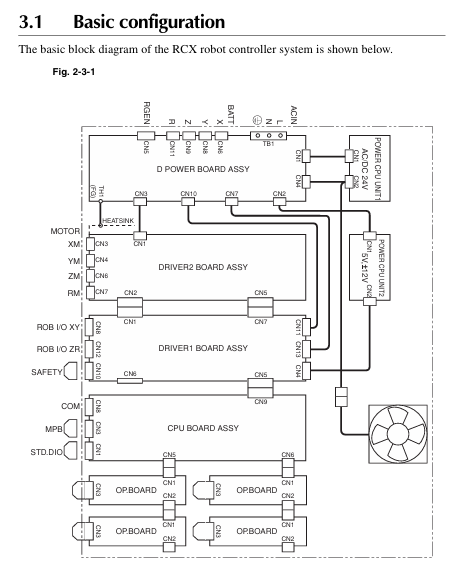
1. System configuration
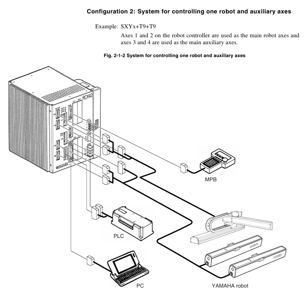
Supports two core configurations: single robot control and single robot+auxiliary axis control (up to 4 axes).
The axis definition includes the main robot axis, main auxiliary axis, sub robot axis, and sub auxiliary axis, which can be switched through the MPB programming unit.
Optional devices include MPB programmer, expansion I/O board (up to 4 pieces), and regeneration unit, adapted to different system requirements.
2. Core functional highlights
Multi tasking function: Up to 8 tasks can be run simultaneously, supporting priority settings to improve system efficiency.
Robot Language: Adopting a high-level language similar to BASIC, in compliance with the industrial robot programming standard SLIM, supporting compilation and execution, and efficient programming.
Motion control: Supports Arch motion (freely set pick and place paths), 3D CP control (linear/arc interpolation motion), and reduces cycle time.
Easy maintenance: Software servo control achieves unit standardization, compatible with most YAMAHA robot models, simplifying maintenance and adjustment.
Compliance: Compliant with the Machinery Directive, Low Voltage Directive, and EMC Directive, supporting SAFE mode operation.
Installation and wiring specifications
1. Installation requirements
Environmental conditions: operating temperature of 0-40 ℃, storage temperature of -10-65 ℃, humidity of 35% -85% (no condensation), avoiding vibration, conductive dust, and corrosive gas environment.
Installation space: Reserve at least 50mm gap on the top and sides, and at least 30mm gap on the back to ensure heat dissipation and ventilation.
Installation method: Supports four installation methods: rubber foot pad installation, front and rear panel L-shaped bracket installation, and side L-shaped bracket installation.
2. Key wiring points
Power connection: Supports AC200-230V single-phase input, requires correct connection of live wire (L), neutral wire (N), and ground wire, and voltage fluctuation should be controlled within ± 10%.
Cable layout: Robot cables need to be separated from power cables to avoid entanglement; When wiring, designated tools must be used to ensure the quality of crimping and welding.
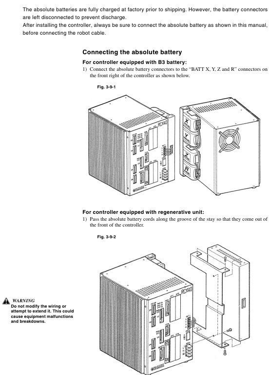
Absolute battery connection: The battery is not connected when it leaves the factory. After installation, the battery needs to be connected first and then the robot cable needs to be connected. The battery needs to be replaced regularly (about 1.5 years).
Emergency stop circuit: It is necessary to correctly connect the emergency stop signal through the SAFETY interface to ensure that the power is quickly cut off when triggered.
Operation mode and core operation
1. Main operating modes
Service mode: Only available in SAFE mode, used for maintenance within safety fences, limiting operating speed (≤ 3% maximum speed), and prohibiting automatic mode operation.
AUTO mode: executes robot programs, supports program reset, task switching, speed adjustment, breakpoint setting, and other functions.
Program mode: Create, edit, and manage robot programs, supporting operations such as program copying, deletion, renaming, and compilation.
MANUAL mode: Manually move the robot, perform point teaching, support absolute reset, coordinate setting, hand definition editing, etc.
SYSTEM mode: Configure system parameters, communication parameters, option functions, support data initialization, backup, and diagnosis.
UTILITY mode: handles auxiliary functions such as emergency stop cancellation, motor power switch, and execution level adjustment.
2. Key operational procedures
Absolute reset: When the origin is lost, it needs to be executed and supports single axis or full axis reset. Before resetting, ensure that the axis is in a safe position.
Program execution: Start the program in AUTO mode and debug it through STEP, SKIP, and NEXT.
Point teaching: In MANUAL mode, use the Jog key to move the robot to the target position and execute the TEACH command to save point data.
Data backup: Backup programs, parameters, point data, etc. to internal flash ROM through SYSTEM mode to avoid data loss.
I/O interface and communication
1. Standard I/O interface
It includes 10 dedicated inputs, 11 dedicated outputs, 16 universal inputs, and 8 universal outputs, and supports NPN/PNP specifications.
Specialized inputs include signals such as servo ON, program start, automatic mode switching, emergency stop, etc; Dedicated outputs include signals such as CPU status, servo status, alarm, program running status, etc.
2. Communication interface
Supports RS-232C interface, can connect to upper computer for data communication, and supports online command execution.
Communication parameters can be configured: baud rate (4800-57600bps), data bits (7/8 bits), stop bits (1/2 bits), parity bits (NONE/ODD/EVENT), etc.
Maintenance and troubleshooting
1. Key points of daily maintenance
Regularly check the absolute battery voltage (normal 3.50-4.3V), and if it is lower than 3.5V, it needs to be charged or replaced.
Regularly backup programs and parameters to avoid data loss caused by hardware failures.
Check if the cable connection is secure to avoid loosening and causing malfunctions.
Clean the controller's cooling fan and fins to ensure good heat dissipation.
2. Fault handling
View error messages through the MPB screen and refer to the "Troubleshooting" section to locate the problem.
Common errors include loss of origin, low battery voltage, program syntax errors, abnormal I/O signals, etc., which require targeted handling.
Malfunctions that cannot be resolved on their own require contacting YAMAHA authorized dealers or technical support.
- YOKOGAWA
- Reliance
- ADVANCED
- SEW
- ProSoft
- WATLOW
- Kongsberg
- FANUC
- VSD
- DCS
- PLC
- man-machine
- Covid-19
- Energy and Gender
- Energy Access
- Renewable Integration
- Energy Subsidies
- Energy and Water
- Net zero emission
- Energy Security
- Critical Minerals
- A-B
- petroleum
- Mine scale
- Sewage treatment
- cement
- architecture
- Industrial information
- New energy
- Automobile market
- electricity
- Construction site
- HIMA
- ABB
- Rockwell
- Schneider Modicon
- Siemens
- xYCOM
- Yaskawa
- Woodward
- BOSCH Rexroth
- MOOG
- General Electric
- American NI
- Rolls-Royce
- CTI
- Honeywell
- EMERSON
- MAN
- GE
- TRICONEX
- Control Wave
- ALSTOM
- AMAT
- STUDER
- KONGSBERG
- MOTOROLA
- DANAHER MOTION
- Bentley
- Galil
- EATON
- MOLEX
- Triconex
- DEIF
- B&W
- ZYGO
- Aerotech
- DANFOSS
- KOLLMORGEN
- Beijer
- Endress+Hauser
- schneider
- Foxboro
- KB
- REXROTH
- YAMAHA
- Johnson
- Westinghouse
- WAGO
- TOSHIBA
- TEKTRONIX
- BENDER
- BMCM
- SMC
- HITACHI
- HIRSCHMANN
- XP POWER
- Baldor
- Meggitt
- SHINKAWA
- Other Brands
- UniOP
- KUKA
- IBA
- Beckhoff
-
LTI SC52.0040.0012.0000.0 - Servo Drive
-
Lti SC52.0040.0012.0000.0 - Servo Drive
-
Milton Industries LTI Tool By Milton LT1240 - 1/2" Drive Lugnut Remover
-
LTi Drives SO84.200.P030.0000.0-W - Servo Spindle Drive
-
LTI DRIVES LSP08-035-320-30-B0R1PY170 - Servo Motor
-
LTI DRIVES SE84.200.SC00.0001.0-W - Servo Drive
-
Lust CDE34.005.W2.2 - Lti Drives Controller
-
LTi SO84.012.0030.0011.2 - ServoOne Servo Drive
-
LTi Drives SO CM-P.0010.11.00.0 - Servo Drive Controller
-
LTi CDE34.017.W3.0 - Servo Drive
-
LTI Drives CDB32.004, C2.0,SH - Positioning Controller
-
LUST CM-CAN1 - LTi DRIVES Communication Module
-
LTi SO84.012.1030.0000.2 - Servo Drive
-
LTI MOOG CDE54.044 - PITCHMASTER FREQUENCY CONVERTER 181-01019
-
MOOG LTI 181-01019 CDE54.044 - PITCHMASTER FREQUENCY CONVERTER
-
Lust LTi Drives CDE34.010,D2.0 - Servo Drive Controller
-
LTI SO84.032.0003.0101.2 - Servo Drive
-
Seagate 9CC132-302 Harris LTI-CS IRT-34-0021-01 - Hard Drive 160GB
-
LTI SO84.032.0003.0001.2 - Servo Drive
-
LTI SO24.007.0070.0000.1 - SERVO CONTROLLER
-
LTi drive CDA32.003.C3.0.H05-01.PC1 - Servo Drive
-
LTI SO84.016.0030.0000.2 - SERVO CONTROLLER
-
LUST LTI CD A34.008,W1.4, BR - SERVO DRIVE
-
MOOG LTI 181-01019 CDE54.044 - PITCHMASTER FREQUENCY CONVERTER
-
LTI MOOG 181-01019 - PITCH Master Servo Drive CDE54.044
-
LTI SERVO ONE SO84.045.0030.0001.2-W - Drive
-
LUST LTi SO84.032.0040.0000.2 - SERVO ONE DRIVE
-
LTi Drives LSH-074-2-30-3 20/T1,G6.1M - SERVO MOTOR
-
LTI SO84.016.0000.0101.2 - servo drive
-
LTI SA54.0550.0033.0000.0 - Servo Drive
-
LTI SA54.0550.0033.0000.0 - Servo Drive
-
LTI LT 4850 - 3/8" Drive 3-Pc Twist Socket Transmission Drain Plug Removal System
-
LTI Tools LT4400-30 Lock Technology - 3/4" Twist Socket 1/2" Drive Lugnut Remover
-
LTI Tools LT-1400C - 1/2 Drive Wheel Torque Extension Tool
-
LTI Tools LT1250 - 1/2" Drive Dual Sided Socket Lug Nut Remover Tool
-
LTI SO84.032.0003.0101.2 - Servo Drive
-
LTI MOOG 181-01019 - PITCH Master Servo Drive CDE54.044
-
MOOG LTI 181-01019 CDE54.044 - PITCHMASTER FREQUENCY CONVERTER
-
MOOG LTI 181-01019 CDE54.044 - PITCHMASTER FREQUENCY CONVERTER
-
MOOG LTI 181-01019 CDE54.044 - PITCHMASTER FREQUENCY CONVERTER
-
LTI SA54.0550.0033.0000.0 - Servo Drive
-
LTI Tools LT-4800 - 7 Piece Twist Socket 3/8" Drive Oil Drain Plug Removal Set
-
LTI SA54.0550.0033.0000.0 - Servo Drive
-
LTI Drive SO24.007.00300000.0 - Servo Drive
-
LTI TOOLS LTI 1400-I - Drive Wheel Torque Extension
-
LTI Tools LT4400-3 - 3/4" 19mm Twist Socket 1/2" Drive Lugnut
-
LTI TOOLS LTI 1400-BB - Drive Wheel Torque Extension
-
LTI SO84.032.0003.0101.2 - Servo Drive
-
LTI Tools LT-4512 - 3/8" Drive 12mm Twist Socket
-
LTI MOTION Luster SO84.032.0003.0001.2 - Servo Drive
-
LTI Tool By Milton LT1600P - 1" Drive Torx Stick
-
LTI Lust VF1424L,HF,OP2,S56 - Variable Frequency Drive
-
LUST CDA32.004,C1.4,H08,B0 - SERVO DFRIVE CM-CAN1 Module
-
LTI SO84.045.0002.0001.2-W - Drive
-
LTI Lust VF1404M,C9,PT1,BR1 - Inverter Type VF1404M
-
LTI SA54.0550.0033.0000.0 - Servo Drive
-
LTI Tools LT-1400C - 1/2" Drive Wheel Torque Extension
-
Lust LTI DRiVES CDA32.006, C3.0, H09 - Variateur De Fr茅quence Frequency Inverter
-
LTI MOOG CDE54.044 - PITCH master SERVO DRIVE
-
LTI MOOG CDE54.044 - PITCH master SERVO DRIVE
-
LTI SO84.143.0020.0101.2-W - servo drive
-
LTI MOTION SC34.0200.0011.0000.0 - Servo drives
-
LTI SO84.032.0003.0001.2 - Servo Drive
-
LTI DRIVES GmbH MS100 - Assembly Set Mounting Kit
-
LTI SO84.032.0003.0001.2 - Servo Drive
-
LTI SO84.032.0003.0001.2 - Servo Drive
-
LTI MOTION SO84.032.0003.0101.2 - servo drive
-
LTI SO84.032.0003.0101.2 - Servo Drive
-
LTI MOOG CDE54.044 - PITCH master SERVO DRIVE
-
LTI MOTION CDE32.004.C2.4 - Servo drives
-
LTI CDD34.032锛學x.x锛孊R锛孭C1 - Servo Drive
-
Lust LTI DRiVES CDA32.006, C3.0, H09 - Inversor De Frecuencia Frequency Inverter
-
Lust SO84.008.0030.1000.0 - Servo One LTi Drive
-
LTI MOTION SO84.032.0003.0101.2 - Servo drives
-
LUST LTi CDA32.004,C1.4 - SERVO DRIVE
-
LTI MOOG CDE54.044 - PITCH Master SERVO DRIVE
-
LTI KEBA CDB32.004 C2.7, SH - PN: 08673530 Frequency Inverter
-
LTI Tools LT-1400C - 1/2" Drive Wheel Torque Extension
-
LTI LT1400-E - 1/2" Drive Wheel Torque Extension
-
LTI MOOG 181-01019 - PITCH master SERVO DRIVE CDE54.044
-
LTI LSN-097-0510-30-560/T1 - Actuator Motor
-
LTI Tools LT 4800 - 7 Piece 3/8" Drive Twist Socket Oil Drain Plug Removal System
-
LTI DRIVES GmbH MS100 - MONTAGESET Assembly Set Mounting Kit
-
Lti SC52.0040.0012.0000.0 - Servo Drive
-
LTI DRIVES GmbH MS100 - Juego De Montaje Assembly Set Mounting Kit
-
LTi DSM4-14.2-21R83-200 - Drives servomoteur Servo Motor
-
MOOG CDE 54.044.GDA - Pitch Master Industrielle Turbine Lti Drive
-
LTI SO24.004.0030.1000.0 - Servo Drive Controller
-
Lti MOOG CDE54.044 - Pitch Master Servo Drive
-
Lust LTI DRiVES CDA32.006, C3.0, H09 - Inverter
-
LTI MOTION GMBH CDB34.006,W3.0,PC1,H39 - Frequency inverter
-
LTI SO84.032.0003.0001.2 - Servo Drive
-
MOOG CDE 54.044.D - Pitch Master Industrielle Turbine Lti Drive
-
LTI TOOLS LT-1460 - 1/2" DRIVE WHEEL TORQUE EXTENSION KIT 5 PIECE SET
-
Lust Cdb32.003, C2.4 - Lti Drives Servoregulador Frecuencia Servo Controller Inverter
-
Lust LTI DRIVES CDA32.006, C3.0, H09 - Frequency Inverter
-
Lust Lti SO82.004.0030.0000.2 - Servo Drive
-
LTI MOTION SC34.0200.0011.0000.0-SL - Servo drives
-
LTI MOTION SA54.0075.0033.0000.0 - Servo drives
-
LTI MOTION SC32.0075.1011.0000.0 - Servo drives
-
LTI Servo-One Junior SO22.006.0080.1000.0 - Servo Controller Servoregler
-
LUST CDA32.004, C1.4, H08, B0 - Servo Drive & LTI CM-CAN1 Module
-
LTI DRIVES LSP08-035-320-30-B0R1PY170 - Servo Motor
-
LUST LTI CDA32.004,C1.4.H08.B0 - SERVO CONTROLLER DRIVES
-
LUST LTi DRiVES CDS44.072LC1.2 - Servo Drive
-
Lti Servo-One Junior SO22.006.0082.1000.0 - Servo Controller Servoregler
-
LUST CDA32.008,C2.0,HF - Lti DRIVES Spindle Drive Inverter
-
LTI SO22.003.0082.0000.0 - Servo Drives One junior Servo Controller Servoregler
-
Lust Lti Drives CM-CAN1 - Communication Module
-
LUST Lti Drives Vf1202s, G8, I6 - Frequency Inverter Drive
-
LTI DRIVES BR-090.03.540.UR.H38 - Bremswiderstand Brake Resistor
-
LTi DRIVES PM-E40.2DRA054P - Wind Turbine Pitch Control Inverter
-
LTi Drives GmbH br-110.01.540-UR - Brake Resistor
-
LTI Drives LSN-097-0960-30-0560/T1,S4,B - Servo Motor
-
LUST CDA34.006.C2.0 - LTI Drives Servoregler
-
LUST LTI DRIVES SERVO ONE JUNIOR SO24.002.0020.0000.1 - Servo Drive Controller
-
LTI MOTION SO84.032.0003.0001.2 - Servo drives
-
LTI DDTD750V2-120 - IBOP ACTUATOR CYLINDER FOR TOP DRIVE
-
LTI CDE32.004, C2.4 - SERVO DRIVE
-
LUST LTI DRIVES CDD34.017 W3.4PC1 - Servo Drive Controller
-
LTI CDA3208,C3,0,HF - AC SERVO DRIVE
-
LUST LTI DRIVES LSH-074-3-30-560/T1,G6.1S - SERVO MOTOR
-
LUST Lti CDB32.004.C2.4.SH - AC Servo Drive
-
LTi CDA32.006, C3.0, H09 - Servo Drive
-
LTI SO22.003.0010.0000.0 - Servo Drive Servo one junior Servoregler Controller
-
LTi Drives DSM4-14.2-21R83-200 - Servo Motor
-
LUST Lti Drives Lsh-097-1-30-560/T1, 1R - Servomotor
-
LTI 1237 - 7 Piece 1/2" Drive Flip Socket Set

K-JIANG

Add: Jimei North Road, Jimei District, Xiamen, Fujian, China
Tell:+86-15305925923