
K-WANG


YOKOGAWA built-in isolation barrier I/O module (FIO specific)
YOKOGAWA built-in isolation barrier I/O module (FIO specific)
Module classification and core technical parameters
1. Simulation module (including HART communication version)
Module Model Type Core Parameters Accuracy Current Consumption (5V DC/24V DC)
ASI133 analog input (built-in isolation gate) with 8 channels and 4-20mA input; 2/4-wire system is optional; Data update cycle 10ms ± 16 µ A 150mA/450mA
ASI133-H analog input (with HART) supports HART communication; Up to 16 devices/modules; 1200bps speed ± 16 µ A 150mA/450mA
ASI533 analog output (built-in isolation gate) with 8 channels and 4-20mA output; Load resistance 0-750 Ω (20mA) ± 48 µ A 150mA/350mA
ASI533-H analog output (with HART) supports HART communication; Multi station connection up to 5 units/channel ± 48 µ A 150mA/350mA
2. Temperature input module
Module Model Type Core Parameters Accuracy (23 ℃) Current Consumption (5V DC/24V DC)
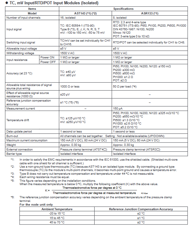
AST143 TC/mV input (built-in isolation barrier) 16 channels; TC supports 8 types (IEC 60584-1); MV range -100~150mV TC: ± 40 µ V; mV: ± 80 µ V 150mA/80mA
ASR133 RTD/BOT input (built-in isolation barrier) with 8 channels; RTD supports Pt/Ni series; POT 0-10kΩ RTD:±150mΩ;POT:±2Ω 150mA / 60mA
3. Digital modules
Module model type Core parameters Response time Current consumption (5V DC/24V DC)
ASD143 digital input (with built-in isolation barrier) 16 channels; NAMUR compatible (IEC 60947-5-6) status input: 15ms 150mA/110mA
ASD533 digital output (built-in isolation barrier) with 8 channels; Output characteristics 12V (40mA), 26V (0mA) 10ms 150mA/500mA
Key characteristics and explosion-proof parameters
1. General characteristics
Electrical protection: All modules have a 1500V AC withstand voltage strength; Input resistance ≥ 1M Ω during power outage;
Environmental adaptability: working temperature -20 to 70 ℃; Compliant with ISA S71.04 G3 level anti-corrosion standard;
Redundancy support: Supports single redundancy/dual redundancy configurations, with dual redundancy installed in adjacent slots (odd+even);
Channel characteristics: module level galvanic isolation, no isolation between channels; The overall explosion-proof function of the module fails when there is a multi-channel short circuit.
2. Explosion proof parameters (ATEX/FM certification)
Module Model ATEX Parameters (Single Redundancy) FM Parameters (Single Redundancy)
ASI133 Uo=27.8V,Io=84mA,Po=584mW Voc=27.8V,Isc=84mA,Po=584mW
AST143 Uo=16.8V, Io=7mA (single channel), Po=30mW Voc=16.8V, Isc=7mA (single channel), Po=30mW
ASD143 Uo=9.8V,Io=21mA,Po=52mW Voc=9.8V,Isc=21mA,Po=52mW
ASD533 Uo=27.16V,Io=108.6mA,Po=738mW Voc=27.16V,Isc=108.6mA,Po=738mW
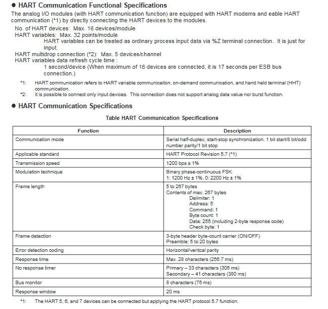
Detailed explanation of HART communication function
1. Core specifications
Communication mode: Serial half duplex, start stop synchronization (1-bit start/8-bit data/1-bit odd parity/1-bit stop);
Applicable standard: HART Protocol Revision 5.7 (compatible with HART 5/6/7 devices);
Transmission rate: 1200bps ± 1%;
Connection capability: up to 16 devices/modules, up to 5 devices/channels for multi station connection (input devices only);
Data refresh: 1 second per device (17 seconds per ESB bus connection for 16 devices).
2. System configuration
Support dual redundancy configuration: Two modules are installed in adjacent slots of the same node unit;
Data flow: FCS reads and writes analog data and HART variables through the I/O mapping area. The HART variables are connected through the% Z terminal and only support input.
Installation and compatibility requirements
1. Hardware compatibility
On site control unit (FCU): AFV30S, AFV30D (equipped with PW481-11/PW482-11/PW48284-11 power modules);
Node units: ANB10S/10D, ANB11S/11D (specific model suffix);
Connection method: pressure clamp terminal (single redundant: ATSA3S/ATSS3S, etc.); Dual redundancy: ATSA3D/ATSS3D, etc.
2. Software and Engineering Requirements
Control function: VP6F1700 on-site control station control function (applicable to AFV30 );
Engineering tool: VP6E5100 standard builder function;
EMC requirement: Shielded cables are required (one layer of shielding can be shared across all channels).
Module size and model code
1. External dimensions (unit: mm)
ASD143: Width 32.8, Height 130, Depth 94 (including protrusion 13.5);
Other modules (ASI133/533, AST143, ASR133, ASD533): Same size as ASD143;
Tolerance standard: 0.5-120mm dimensional tolerance ± 0.8mm, combination tolerance ± 1.5mm; follow JEM 1459 for dimensions greater than 120mm.
2. Model coding rules (taking ASI133 as an example)
Basic model: ASI133 (analog input, built-in isolation gate);
Suffix codes: - S (standard type), - H (with HART), 00 (fixed position);
Option codes:/SA3S0 (single redundant pressure clamp terminal),/SA3D0 (dual redundant pressure clamp terminal).
Key issues
Question 1: What is the explosion-proof adaptation scenario for the built-in isolation barrier I/O module in this series? What are the core requirements to pay attention to during installation?
answer:
Explosion proof adaptation scenario: The module can be installed in Zone 2/Division 2 environment and can connect to on-site equipment in Zone 0/1/Division 1, complying with ATEX and FM3610 certification standards;
Core installation requirements:
Hardware compatibility: Only compatible with specific models of AFV30 series FCU and ANB10/11 series node units, requiring PW481-1/PW482-11/PW482-11/PW48841-11 power modules;
Wiring requirements: Shielded cables must be used to avoid simultaneous short circuits in multiple channels (otherwise the explosion-proof function of the module will fail);
Redundant configuration: Dual redundancy should be installed in adjacent slots (odd+even), and the terminals should use dual redundancy pressure clamp terminals;
Environmental restrictions: Operating temperature -20 to 70 ℃, following ISA S71.04 G3 level anti-corrosion requirements.
Question 2: What are the core communication features of the module with HART communication function (ASI133-H/ASI533-H)? What scenarios are applicable?
answer:
Core communication characteristics:
Communication parameters: 1200bps rate, serial half duplex mode, compatible with HART Protocol Revision 5.7;
Connection capability: up to 16 devices/modules, supporting 5 devices/channels for multi station connection (input devices only);
Data processing: HART variables are connected through the% Z terminal and only support input. The data refresh cycle is 1 second per device;
Redundancy support: Can be configured with dual redundancy, consistent with the installation requirements of ordinary modules.
Applicable scenarios: In explosion-proof environments where analog signal transmission and remote monitoring of equipment are required (such as in the petroleum and chemical industries), additional parameters of on-site equipment (such as equipment status and diagnostic information) can be read through the HART protocol without the need for additional wiring.
Question 3: What are the differences in the number of channels, accuracy, and current consumption among different types of modules? How to select based on demand?
answer:
Summary of core differences:
Module type Channel number Accuracy range 24V DC Current consumption
Analog input (ASI133) 8 ± 16 µ A 450mA
Analog output (ASI533) 8 ± 48 µ A 350mA
TC/mV input (AST143) 16 ± 40~80 µ V 80mA
RTD/BOT input (ASR133) 8 ± 150m Ω~± 2 Ω 60mA
Digital input (ASD143) 16- (NAMUR compatible) 110mA
Digital output (ASD533) 8- (10ms response) 500mA
Selection principle:
Signal type: Select AST143 (multi-channel TC/mV) or ASR133 (RTD/BOT) for temperature signal; Analog selection ASI133/533; Select ASD143/533 for switch quantity;
Accuracy requirement: Select ASI133 (± 16 µ A) for high-precision analog acquisition; Select AST143 (± 40 µ V) for temperature acquisition;
Power consumption limitation: ASR133 (60mA) or AST143 (80mA) is preferred for low-power scenarios;
Expansion requirement: Remote monitoring equipment with HART ASI133-H/ASI533-H needs to be selected.
- YOKOGAWA
- Reliance
- ADVANCED
- SEW
- ProSoft
- WATLOW
- Kongsberg
- FANUC
- VSD
- DCS
- PLC
- man-machine
- Covid-19
- Energy and Gender
- Energy Access
- Renewable Integration
- Energy Subsidies
- Energy and Water
- Net zero emission
- Energy Security
- Critical Minerals
- A-B
- petroleum
- Mine scale
- Sewage treatment
- cement
- architecture
- Industrial information
- New energy
- Automobile market
- electricity
- Construction site
- HIMA
- ABB
- Rockwell
- Schneider Modicon
- Siemens
- xYCOM
- Yaskawa
- Woodward
- BOSCH Rexroth
- MOOG
- General Electric
- American NI
- Rolls-Royce
- CTI
- Honeywell
- EMERSON
- MAN
- GE
- TRICONEX
- Control Wave
- ALSTOM
- AMAT
- STUDER
- KONGSBERG
- MOTOROLA
- DANAHER MOTION
- Bentley
- Galil
- EATON
- MOLEX
- Triconex
- DEIF
- B&W
- ZYGO
- Aerotech
- DANFOSS
- KOLLMORGEN
- Beijer
- Endress+Hauser
- schneider
- Foxboro
- KB
- REXROTH
- YAMAHA
- Johnson
- Westinghouse
- WAGO
- TOSHIBA
- TEKTRONIX
- BENDER
- BMCM
- SMC
- HITACHI
- HIRSCHMANN
- XP POWER
- Baldor
- Meggitt
- SHINKAWA
- Other Brands
- UniOP
- KUKA
- IBA
- Beckhoff
- ADLINK
-
ADLINK HPCI-14S12U - Industrial Control Backplane 12PCI Backplane PCI-14S Passive Backplane
-
ADLINK PCIe-GIE74C - image acquisition card 4-CH GigE Vision PoE+ Frame Grabber
-
ADLINK PCI-8164 - control card 4-Axis Advanced Motion Controller Board
-
ADLINK PCIe-U304 - 4 Port USB3 PCIe Frame Grabbers USB Screw Hole Card
-
ADLINK PCI-9112 - Multi-Function Data Acquisition Card DAQ Card
-
ADLINK PCI-7432 - 51-12013-0A50 4-CH Isolated Numérique I/O PCI Cartes Digital I/O Card
-
ADLINK PCA-6106P3-0C1 REV.C1 - backplane 6-Slot Passive Backplane Board
-
ADLINK PCI-7224 - 24-CH Opto-Isolated Digital I/O PCI Board
-
ADLINK CPCI-7433R(G) - Digital Input Board Rear I/O CompactPCI Card
-
ADLINK EBP-13E4 - 51-46703-0A30 Industrial PC Backplane Passive Backplane
-
ADLINK PCIE-HDV62 - Image acquisition card High Definition Video Frame Grabber
-
ADLINK EBP-13E4 - 51-46703-0A30 Industrial Backplane Board Passive Backplane
-
ADLINK 90111-B1 / CPCI-6770 - PCB CPU MODULE CompactPCI Single Board Computer
-
ADLINK PCI-7248 - DATA ACQUISITION PCI CARD 48-CH Parallel Digital I/O Board
-
ADLINK PCI-7230 - 51-12003-0a50 board PCI7230 32-CH Isolated Digital I/O Card
-
ADLINK PCI2A000CB - 51-20000-0B30 Multi-Function DAQ Card Baseboard
-
ADLINK PCI-8134-005 - 4-Axis Motion Controller Card
-
ADLINK PCI-7224 - 24-CH Opto-Isolated Digital I/O PCI Card
-
ADLINK PCI-7434 - 64-CH Isolated Digital Output Card
-
ADLINK PCI-8132 - motion control card 2-Axis Servo & Stepper Controller
-
ADLINK PCI-8134 - Motion Controller PCI Card 4-Axis Controller Board
-
ADLINK PCI-8164 - Motion Control Card 51-12406-0A40 4-Axis Controller
-
ADLINK 51-12001-0C20 - Circuit Board Data Acquisition Interface Module Hardware
-
ADLINK NuPR0-840 - industrial control motherboard Full-Size PICMG CPU Board
-
ADLINK PCI-7444 - 51-12023-0A10 card 128-CH Isolated Digital Output Board
-
ADLINK PCI-1612B - data acquisition card 4-Port RS-232/422/485 Serial Communication Card
-
ADLINK PCI-6208V 009 - 8/16-CH 16-Bit Analog Output Cards PCB-I-E-482=6BX3
-
ADLINK NUPRO-935A/LV - industrial control motherboard Full-Size PICMG SBC Board
-
ADLINK PCI-9114DG - Multi-Function DAQ Card Data Acquisition PCI Card
-
ADLINK ACL-7130 - Data acquisition card Isolated Digital I/O Board
-
ADLINK ABX-6300D-4E1-BP - board ABX6300D4E1BP Video Interface Expansion Card
-
ADLINK CPCI-6940 - CPCI-6940/D1539/M16-0(EA)-000E 6U CompactPCI Processor Board
-
ADLINK NuPRO-760 - industrial control motherboard Half-Size PICMG SBC CPU Board
-
ADLINK IMB-M42H (G)-0020 - industrial control motherboard LGA1155 Micro-ATX Mainboard
-
ADLINK RTV-24 / PCI-MP4S - 51-12519-1C30 4-Channel Real Time Video Capture Board
-
ADLINK PCI-8134 - 4-Axis Servo & Stepper Motion Controller Card
-
ADLINK MXC-6101D - V.PC000.002.ST.00 Box PC Configurable Embedded Computer
-
ADLINK PCI-8134A - 51-12421-0A10 Motion Control Card 4-Axis Controller Card
-
ADLINK DIN-100S / DIN-100SA1 - Technology SCSI-II TB 100-PIN Terminal Block Board
-
ADLINK DIN-812M001 / DIN812M001 - 51-14034-0A1 51140340A1 Terminal Module Breakout Interface
-
ADLINK PCI-8164 - Servo motion control 4-Axis Advanced Controller Card
-
ADLINK PCIe-GIE64 - Acquisition card GigE Vision PoE+ Frame Grabber
-
ADLINK M-302 - Industrial control motherboard ATX PC Board Mainboard
-
ADLINK PCI-8134 - Motion Controller PCI Card 4-Axis Controller Board
-
ADLINK PCI-RTV24 - Image capture card Analog Video Frame Grabber
-
ADLINK PCI-8102 - Motion control card 2-Axis Servo & Stepper Controller Board
-
ADLINK PCI-9112 REV.B1 - Card Multi-Function Data Acquisition Card
-
ADLINK HSI-DI32-M-N / HSL-TB32-M-DIN - Discrete I/O MODULE Distributed Automation Module System
-
ADLINK PCI-7296 - IO card REV.A3 96-CH Parallel Digital I/O Card
-
ADLINK DIN-814P-A4 / 814Y - terminal board Motion Control Interface Block
-
ADLINK DIN-814P-A4 - 51-14056-0A10 PCB-I-E-2736=ZA01 Screw Terminal Board Breakout
-
ADLINK M-322 - motherboard Industrial Control Computer Mainboard
-
ADLINK NUPRO-406 REV:B1 - industrial control motherboard Full-Size PICMG CPU Board
-
ADLINK AMP-204C - card DSP-Based 4-Axis Advanced Pulse-Train Controller
-
ADLINK HPCI14S REV.B1 - industrial computer baseboard 14-Slot Passive Backplane
-
ADLINK PCI-7250 - 8-CH Relay Output & 8-CH Isolated DI PCI Card
-
ADLINK EBP-13E2 - baseplate Passive Backplane Industrial Computer Chassis Board
-
ADLINK LPCI-3488A - PCI-GPIB card 51-12801-0A30 acquisition card IEEE-488 Interface Board
-
ADLINK PCI-6216V-GL - 51-12201-0C30 16-CH 16-Bit Voltage Analog Output Card
-
ADLINK ACL-8454 - 16-CH Isolated Digital I/O & 4-CH Counter Card
-
ADLINK HPCI-9S7U - backplane Passive Backplane Compatible with NuPRO-A301 852 841 842
-
ADLINK DAQ-2010-007 - Simultaneous-Sampling Multi-Function Data Acquisition Card
-
ADLINK MP-C154 - 51-64205-0A10 Motion Control Card 4-Axis Controller Board
-
ADLINK MXE-202/mSSD16B/WiFi-BT - Matrix Rugged I/O Platform Embedded Fanless Computer
-
ADLINK CM-920-R-17 - PC/104-Plus Single Board Computer Module Intel Celeron M
-
ADLINK PCI-7250 NSMP - 8-CH Relay Output & 8-CH Isolated DI Card
-
ADLINK PCI-8164 - 4-Axis Motion Controller PCI Card W/ Cable and Breakout Box
-
ADLINK EMX-100 - Ethernet-based 4-axis Motion Controllers Distributed Motion Module
-
ADLINK PCI-8134A - Press control card 4-Axis Motion Controller Board
-
ADLINK M-845EG REV:3.2 - industrial motherboard Pentium 4 Socket 478 Micro-ATX
-
ADLINK PCI-9114A Rev A2 DG - card High-Resolution Multi-Function Data Acquisition Board
-
ADLINK IEC-915GV - REV 1.1 Industrial motherboard Socket 478 CPU Board
-
ADLINK PCI-9111DG(G) - Data Acquisition Card Multi-Function DAQ Card
-
ADLINK HPCI-15S10 REV:B2 - Industrial computer base plate Passive Backplane Board
-
ADLINK NuPR0-840 / NuPR0-840DV - industrial control motherboard Full-size PICMG CPU Board
-
ADLINK RTV-24 / PCI-MP4S - 51-12519-1C30 4-Channel Real Time Video Capture Board
-
ADLINK NUPRO-780 - industrial control motherboard Pentium III Single Board Computer
-
ADLINK PCI-7296 - 0050 card 96-CH Opto-Isolated Parallel DIO Card Set
-
ADLINK NUPRO-780 - industrial control motherboard PICMG Full-Size SBC
-
ADLINK PCI-7248 - 51-12006-0A3 002 Pci 7248 48-CH Parallel Digital I/O Card
-
ADLINK cPCI-6626 - 6U CompactPCI 2.0 Blades i7-2710QE PCB-I-E-2570=9N41
-
ADLINK MXC-6322D(G) - Industrial Fanless Computer
-
ADLINK cPCI-8168-004 - CompactPci NulPC Motion Control Board 51-36402-0A3
-
ADLINK CPCI-7300[G] - COMPACTPCI Digital I/O Card Data Acquisition
-
ADLINK CPCI-6626/2710/M4G - COMPACTPCI COMPUTER BOARD
-
ADLINK cPCI-8168-009 - cPCI NulPC Motion Control Board
-
ADLINK cPCI-6626/2710/M4G - VME CPU Board Computer Board
-
ADLINK CPCI-R6200(G)-0040 - COMPACTPCI CONTROL BOARD
-
ADLINK CPCI-3840/PM18/M1G(G)-3650 - COMPACTPCI CPU Module Single Board Computer
-
ADLINK cPCI-7248 - 48-CH Opto-22 Compatible Digital I/O Module
-
ADLINK DLAP-211-JNX - NVIDIA Jetson Xavier NX Edge AI Inference Platform
-
ADLINK cPCI-3544 - Series 4-Port RS-422/485 Isolated Serial Communications Card
-
ADLINK CM1-86DX3 - PC/104 SBC Stanley Vortex86DX3 CPU 2GB Ram
-
ADLINK DLAP-211-JNX - NVIDIA Jetson Xavier NX Edge AI Inference Platform
-
ADLINK cPCI-3544 - Series 4-Port RS-422/485 Isolated Serial Communications Card
-
ADLINK CM1-86DX3 - PC/104 SBC Stanley Vortex86DX3 CPU 2GB Ram
-
ADLINK PCI-7433 - switch value acquisition card Isolated Digital Input Card
-
ADLINK PCI-9112 - 51-12252-0D20 Multi-Function Data Acquisition Card
-
ADLINK NUPRO-A301 REV:1.4 - industrial control motherboard PICMG Full-Size SBC
-
ADLINK 51-18502-0A10 - Frame Grabber Image Acquisition Interface Card
-
ADLINK PCI-7296 - 51-12009-0A50 PCB-I-E-925=6DX1 96-CH Parallel Digital I/O Board
-
ADLINK PCI-8132 GP A2 - Motion Control Card 2-Axis Servo & Stepper Controller
-
ADLINK PCI-7442 - switch quantity card data acquisition card 64-CH Isolated Card
-
ADLINK HPX-13S4 - baseboard PICMG 1.3 Passive Backplane Chassis Baseplate
-
ADLINK NuPRO-590 / NTC-567-ZM-F36 - Single Board Computer PCB-I-E-1853=9L21 Half-Size SBC
-
ADLINK PCIe-8332 - 16-axis plate Motion Control Hardware Card
-
ADLINK NuPRO-775 REV.B1 - motherboard Pentium 4 Full-Size PICMG SBC
-
ADLINK PXI-3920 - Embedded Controller 3U PXI cPCI System Intelligence Board
-
ADLINK PCI-8134 - driver card motion control card 4-Axis Controller Board
-
ADLINK HSL-DI32-M-N-011 / HSL-TB32-M-DIN - Digital Input & Base Module PLC Distributed I/O System
-
ADLINK PCI-6216V-206 / PCI-208V 009 - 16 CH 16bit analog output card
-
ADLINK NuPro-E330 - 51-41805-0A20 PCB Single Board Computer Host Board
-
ADLINK PCI-1622C - Card 8-Port RS-232/422/485 PCI Serial Communication Board
-
ADLINK PCIe-7432 - 51-18402-0A10 Carte PCIe Avec Plage D'Entrée Élevée Isolated DIO Card
-
ADLINK PCI-7250 - PCI Acquisition Card 8-CH Relay Output Isolated DI Card
-
ADLINK PCI-7230 - 32-CH Isolated Digital I/O Card
-
ADLINK PCI-8164 - PCB 4-Axis Motion Controller Card
-
ADLINK PCI-7854 - Collection card High-Speed Link Distributed Motion Controller
-
ADLINK NuPRO-935A/LV - industrial control computer motherboard Full-Size PICMG SBC
-
ADLINK IMB-M40H - motherboard IH61-AA4 1155 LGA1155 Micro-ATX Mainboard
-
ADLINK PCI-7248 - Linhua 51-12006-0A40 48-CH Parallel Digital I/O Card
-
ADLINK HPCI-14S12U - Linhua industrial computer baseboard Passive Backplane
-
ADLINK PCI-8132 Rev.A2 - 2-Axis Servo & Stepper Motion Controller Card
-
ADLINK ACL-8111 - ISA card Multi-Function DAQ Card
-
ADLINK ACL-8111 - ISA card Multi-Function Data Acquisition Board
-
ADLINK PCI-7200 REV.A3 - Digital I/O card 12MB/s High-Speed Parallel Digital I/O
-
ADLINK PCI-7296 REV.A3 - 96-CH High-Density Opto-Isolated DIO Card
-
ADLINK PCI-7434 - 64-CH Isolated Digital Output Card

K-JIANG

Add: Jimei North Road, Jimei District, Xiamen, Fujian, China
Tell:+86-15305925923