
K-WANG


EATON KD, HKD, KDC, CKD, CHKD K-frame molded case circuit breakers
EATON KD, HKD, KDC, CKD, CHKD K-frame molded case circuit breakers
Product Basic Core Information
Applicable models and configurations: The circuit breaker models are KD, HKD, KDC, CKD, CHKD, all of which are K-frame Series C, compatible with Digitrip OPTIM trip units, and support Powernet communication and/or regional interlocking functions; The OPTIM 750/1050 model is additionally equipped with auxiliary switches, alarm/lock switches, and other internal accessories need to be factory installed.
Rated and Application: Maximum rated voltage of 600 VAC, only applicable to AC scenarios; The maximum continuous current of the trip unit is three specifications: 125A, 250A, and 400A.
Certification standard: Complies with the US UL 489 standard and meets the (P1) requirements of international IEC 157-1.
100% rated operating model: CKD and CHKD models can operate continuously at 100% frame rating if they meet the following conditions: using 90 ℃ insulated wires and AL9CU terminals, installed in a 24 "high x 15" wide x 6 "deep enclosure, which does not require additional ventilation.
Supporting materials: Selection data, trip unit operation manual, wiring diagram and other materials (such as numbers 29-120K, 29C890, etc.) can be obtained from Eaton.
Full process installation specifications
The installation process includes pre inspection → accessory installation → fixation → wiring → protection → parameter setting. All steps must be carried out under power-off, and the key requirements are as follows:
Pre-check
Check the circuit breaker nameplate and system requirements, and confirm that the equipment is not damaged during transportation;
Before removing the circuit breaker cover, it must be placed in the trip or OFF position.
Installation of internal accessories
The rated plug and internal accessories need to be installed before fixing the circuit breaker, refer to the separate instructions for the accessories;
When reinstalling the cover plate, the threaded forming screws should be aligned with the original threads to avoid thread damage that may cause the cover plate to be loosely fixed.
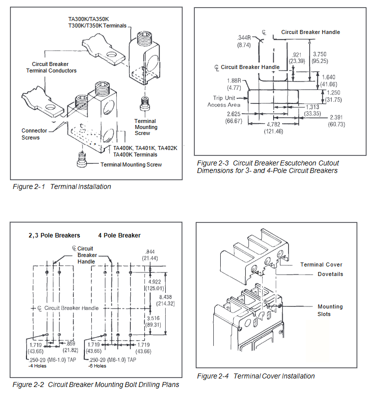
Terminal installation
The wire terminal is fixed with a 7/32 inch socket wrench, with a torque of 6-8 lb. - ft. (8-11 N.m.);
When connecting aluminum wires, a suitable joint compound must be applied to prevent the terminals from overheating and causing accidental tripping or equipment damage.
Circuit breaker fixing
Surface installation should be drilled according to Figure 2-2, while panel installation only requires support holes at the load end. Concealed cover installation should be cut according to the dimensions shown in Figure 2-3;
Tighten the installation screws and washers firmly and not exceeding 28 lb. in. (3 N.m.);
The side of the circuit breaker is labeled with a wiring diagram of the accessories. If it is not visible after installation, it needs to be recorded in advance.
Wiring specifications
The control power supply is 24VDC, the trip unit load is 45mA, and the positive and negative poles must be connected to the corresponding terminals (No. 6+24V/No. 5 NEG). Reversing the connection will damage the electronic protection function;
The regional interlocking function requires the removal of the factory jumper between terminals 2 and 3. If it is not removed, it will be in a self interlocking state;
The four wire system requires the installation of a neutral current sensor at the neutral pole, arranged according to the dimensions shown in Figure 2-6.
Rated plug selection
The release unit needs to be matched with the corresponding rated plug, with specifications as shown in the table below:
The rated current of the trip unit can be selected according to the rated plug specifications
125A 63A、70A、90A、100A、110A、125A
250A 125A、150A、160A、175A、200A、225A、250A
400A 200A、225A、250A、300A、350A、400A
Terminal torque and protection
The torque of the wire/load terminal is determined according to the model, and the core specifications are shown in the table below:
Terminal model material applicable wire torque value (lb. in./N.m.)
TA300K/T300K Aluminum/Copper 3-350 AWG 275/31
TA350K/T350K Aluminum/Copper 250-500 AWG 375/42
TA402K Aluminum 500-750 AWG 550/62
Ladder type terminals (TA400K/TA401K, etc.) must be equipped with matching terminal shields and warning labels must be affixed to the upper part of the circuit breaker cover plate;
When wiring, it is necessary to maintain the original factory electrical clearance and creepage distance to prevent high voltage hazards.
Parameter Settings
Insert the Digitrip OPTIMZER handheld programmer into the programming port, set the INCOM address and trip unit current parameters;
Parameters can also be set through the circuit breaker interface module or IMPACC Series III software.
Manual operation method
The manual operation of the circuit breaker is achieved through the operation handle and PUSH-TO-TRIP button, without additional electric operation requirements. Key rules:
operating handle
There are three positions: ON, OFF, and release. The cover plate is engraved with ON/OFF, and the handle color bar is marked with red=ON, green=OFF (reset), and white=release;
Reset after tripping: simply turn the handle to the extreme OFF position. The reset button is only used to reset the fault indicator light and does not affect the mechanical reset of the circuit breaker.
PUSH-TO-TRIP button
Used to trigger the trip function and regularly test the flexibility of the operating mechanism;
Use a small screwdriver to operate, designed for mechanical triggering.
Safety principle: After the circuit breaker is tripped, it is strictly prohibited to close it again until the fault is identified and eliminated.
Inspection and on-site testing
This series of circuit breakers is designed for maintenance free use and only requires limited regular inspections and testing. All operations must be performed with power off. The core requirements are:
Daily inspection (4-1 to 4-7)
Cleaning: Use a lint free dry cloth/brush/vacuum cleaner to remove dust, do not blow debris into the interior of the circuit breaker, and investigate the source of pollution;
Mechanical testing: repeatedly turn the handle to ON/OFF to ensure that the mechanism is not stuck. If it is stuck, replace the circuit breaker;
Trip test: Press PUSH-TO-TRIP in the ON position and repeatedly trip reset close. If the reset fails, replace the circuit breaker;
Component inspection: Check the cover plate, handle, and base for cracks, paint peeling, and discoloration. If they are severely damaged, replace them;
Terminal inspection: Check that the terminals are not loose or overheated (discoloration/insulation melting/arc erosion). If there are no problems, do not tighten them randomly. If there is overheating, clean/replace the terminals and restore them to their original factory condition;
Installation component inspection: tighten loose installation screws;
Environmental inspection: Check for chemical corrosion, personal/fire hazards in the installation area.
General on-site testing
Execute according to NEMA standards and test the functionality of the Digitrip OPTIM trip unit using the OPTIMIZER handheld programmer.
Grounding fault trip unit test (mandatory requirement)
Regulatory requirements: According to NEC 230-95-C, the grounding fault protection system must undergo performance testing when newly installed, and written test records must be retained in accordance with UL 1053 requirements for inspection by inspection agencies;
Test power supply: Use a 0-24V low-voltage, high current AC source, and do not only test through neutral sensors (the trip unit is powered by phase current, not neutral current);
Trip test: Apply a current of 125% of the ground fault setting value to any phase, and the circuit breaker should trip within 1 second. The alarm indicator light (if any) should be activated, and the three phases should be tested separately;
Non trip verification:
Four wire system (with neutral sensor): current flows in from one phase, neutral sensor flows out, circuit breaker does not trip, and three phases are tested separately;
Three wire system (without neutral sensor): Current flows between any two phases without tripping the circuit breaker, and all phase combinations are tested separately;
Attention: On site testing is only for functional verification and cannot be used for on-site calibration. Temporary wiring for testing must be restored to its original state before power can be transmitted.
Safety Warning and Disclaimer
Core safety requirements: All installation, maintenance, and testing operations must be powered off and verified to have no voltage to avoid high voltage causing death/serious injury/property damage;
Material protection: Do not use corrosive commercial cleaning agents to prevent damage to nameplates and molded parts;
Nuclear application reminder: This instruction applies to general commercial scenarios, and additional instructions for nuclear facility safety related applications need to be obtained from Eaton;
Disclaimer: Eaton shall not be liable for any misuse or installation of the product. This statement is not exhaustive and does not provide any express or implied warranties. Eaton shall not be liable for any special, indirect, or consequential damages.

- YOKOGAWA
- Reliance
- ADVANCED
- SEW
- ProSoft
- WATLOW
- Kongsberg
- FANUC
- VSD
- DCS
- PLC
- man-machine
- Covid-19
- Energy and Gender
- Energy Access
- Renewable Integration
- Energy Subsidies
- Energy and Water
- Net zero emission
- Energy Security
- Critical Minerals
- A-B
- petroleum
- Mine scale
- Sewage treatment
- cement
- architecture
- Industrial information
- New energy
- Automobile market
- electricity
- Construction site
- HIMA
- ABB
- Rockwell
- Schneider Modicon
- Siemens
- xYCOM
- Yaskawa
- Woodward
- BOSCH Rexroth
- MOOG
- General Electric
- American NI
- Rolls-Royce
- CTI
- Honeywell
- EMERSON
- MAN
- GE
- TRICONEX
- Control Wave
- ALSTOM
- AMAT
- STUDER
- KONGSBERG
- MOTOROLA
- DANAHER MOTION
- Bentley
- Galil
- EATON
- MOLEX
- Triconex
- DEIF
- B&W
- ZYGO
- Aerotech
- DANFOSS
- KOLLMORGEN
- Beijer
- Endress+Hauser
- schneider
- Foxboro
- KB
- REXROTH
- YAMAHA
- Johnson
- Westinghouse
- WAGO
- TOSHIBA
- TEKTRONIX
- BENDER
- BMCM
- SMC
- HITACHI
- HIRSCHMANN
- XP POWER
- Baldor
- Meggitt
- SHINKAWA
- Other Brands
- UniOP
- KUKA
- IBA
- Beckhoff
-
LTI SC52.0040.0012.0000.0 - Servo Drive
-
Lti SC52.0040.0012.0000.0 - Servo Drive
-
Milton Industries LTI Tool By Milton LT1240 - 1/2" Drive Lugnut Remover
-
LTi Drives SO84.200.P030.0000.0-W - Servo Spindle Drive
-
LTI DRIVES LSP08-035-320-30-B0R1PY170 - Servo Motor
-
LTI DRIVES SE84.200.SC00.0001.0-W - Servo Drive
-
Lust CDE34.005.W2.2 - Lti Drives Controller
-
LTi SO84.012.0030.0011.2 - ServoOne Servo Drive
-
LTi Drives SO CM-P.0010.11.00.0 - Servo Drive Controller
-
LTi CDE34.017.W3.0 - Servo Drive
-
LTI Drives CDB32.004, C2.0,SH - Positioning Controller
-
LUST CM-CAN1 - LTi DRIVES Communication Module
-
LTi SO84.012.1030.0000.2 - Servo Drive
-
LTI MOOG CDE54.044 - PITCHMASTER FREQUENCY CONVERTER 181-01019
-
MOOG LTI 181-01019 CDE54.044 - PITCHMASTER FREQUENCY CONVERTER
-
Lust LTi Drives CDE34.010,D2.0 - Servo Drive Controller
-
LTI SO84.032.0003.0101.2 - Servo Drive
-
Seagate 9CC132-302 Harris LTI-CS IRT-34-0021-01 - Hard Drive 160GB
-
LTI SO84.032.0003.0001.2 - Servo Drive
-
LTI SO24.007.0070.0000.1 - SERVO CONTROLLER
-
LTi drive CDA32.003.C3.0.H05-01.PC1 - Servo Drive
-
LTI SO84.016.0030.0000.2 - SERVO CONTROLLER
-
LUST LTI CD A34.008,W1.4, BR - SERVO DRIVE
-
MOOG LTI 181-01019 CDE54.044 - PITCHMASTER FREQUENCY CONVERTER
-
LTI MOOG 181-01019 - PITCH Master Servo Drive CDE54.044
-
LTI SERVO ONE SO84.045.0030.0001.2-W - Drive
-
LUST LTi SO84.032.0040.0000.2 - SERVO ONE DRIVE
-
LTi Drives LSH-074-2-30-3 20/T1,G6.1M - SERVO MOTOR
-
LTI SO84.016.0000.0101.2 - servo drive
-
LTI SA54.0550.0033.0000.0 - Servo Drive
-
LTI SA54.0550.0033.0000.0 - Servo Drive
-
LTI LT 4850 - 3/8" Drive 3-Pc Twist Socket Transmission Drain Plug Removal System
-
LTI Tools LT4400-30 Lock Technology - 3/4" Twist Socket 1/2" Drive Lugnut Remover
-
LTI Tools LT-1400C - 1/2 Drive Wheel Torque Extension Tool
-
LTI Tools LT1250 - 1/2" Drive Dual Sided Socket Lug Nut Remover Tool
-
LTI SO84.032.0003.0101.2 - Servo Drive
-
LTI MOOG 181-01019 - PITCH Master Servo Drive CDE54.044
-
MOOG LTI 181-01019 CDE54.044 - PITCHMASTER FREQUENCY CONVERTER
-
MOOG LTI 181-01019 CDE54.044 - PITCHMASTER FREQUENCY CONVERTER
-
MOOG LTI 181-01019 CDE54.044 - PITCHMASTER FREQUENCY CONVERTER
-
LTI SA54.0550.0033.0000.0 - Servo Drive
-
LTI Tools LT-4800 - 7 Piece Twist Socket 3/8" Drive Oil Drain Plug Removal Set
-
LTI SA54.0550.0033.0000.0 - Servo Drive
-
LTI Drive SO24.007.00300000.0 - Servo Drive
-
LTI TOOLS LTI 1400-I - Drive Wheel Torque Extension
-
LTI Tools LT4400-3 - 3/4" 19mm Twist Socket 1/2" Drive Lugnut
-
LTI TOOLS LTI 1400-BB - Drive Wheel Torque Extension
-
LTI SO84.032.0003.0101.2 - Servo Drive
-
LTI Tools LT-4512 - 3/8" Drive 12mm Twist Socket
-
LTI MOTION Luster SO84.032.0003.0001.2 - Servo Drive
-
LTI Tool By Milton LT1600P - 1" Drive Torx Stick
-
LTI Lust VF1424L,HF,OP2,S56 - Variable Frequency Drive
-
LUST CDA32.004,C1.4,H08,B0 - SERVO DFRIVE CM-CAN1 Module
-
LTI SO84.045.0002.0001.2-W - Drive
-
LTI Lust VF1404M,C9,PT1,BR1 - Inverter Type VF1404M
-
LTI SA54.0550.0033.0000.0 - Servo Drive
-
LTI Tools LT-1400C - 1/2" Drive Wheel Torque Extension
-
Lust LTI DRiVES CDA32.006, C3.0, H09 - Variateur De Fr茅quence Frequency Inverter
-
LTI MOOG CDE54.044 - PITCH master SERVO DRIVE
-
LTI MOOG CDE54.044 - PITCH master SERVO DRIVE
-
LTI SO84.143.0020.0101.2-W - servo drive
-
LTI MOTION SC34.0200.0011.0000.0 - Servo drives
-
LTI SO84.032.0003.0001.2 - Servo Drive
-
LTI DRIVES GmbH MS100 - Assembly Set Mounting Kit
-
LTI SO84.032.0003.0001.2 - Servo Drive
-
LTI SO84.032.0003.0001.2 - Servo Drive
-
LTI MOTION SO84.032.0003.0101.2 - servo drive
-
LTI SO84.032.0003.0101.2 - Servo Drive
-
LTI MOOG CDE54.044 - PITCH master SERVO DRIVE
-
LTI MOTION CDE32.004.C2.4 - Servo drives
-
LTI CDD34.032锛學x.x锛孊R锛孭C1 - Servo Drive
-
Lust LTI DRiVES CDA32.006, C3.0, H09 - Inversor De Frecuencia Frequency Inverter
-
Lust SO84.008.0030.1000.0 - Servo One LTi Drive
-
LTI MOTION SO84.032.0003.0101.2 - Servo drives
-
LUST LTi CDA32.004,C1.4 - SERVO DRIVE
-
LTI MOOG CDE54.044 - PITCH Master SERVO DRIVE
-
LTI KEBA CDB32.004 C2.7, SH - PN: 08673530 Frequency Inverter
-
LTI Tools LT-1400C - 1/2" Drive Wheel Torque Extension
-
LTI LT1400-E - 1/2" Drive Wheel Torque Extension
-
LTI MOOG 181-01019 - PITCH master SERVO DRIVE CDE54.044
-
LTI LSN-097-0510-30-560/T1 - Actuator Motor
-
LTI Tools LT 4800 - 7 Piece 3/8" Drive Twist Socket Oil Drain Plug Removal System
-
LTI DRIVES GmbH MS100 - MONTAGESET Assembly Set Mounting Kit
-
Lti SC52.0040.0012.0000.0 - Servo Drive
-
LTI DRIVES GmbH MS100 - Juego De Montaje Assembly Set Mounting Kit
-
LTi DSM4-14.2-21R83-200 - Drives servomoteur Servo Motor
-
MOOG CDE 54.044.GDA - Pitch Master Industrielle Turbine Lti Drive
-
LTI SO24.004.0030.1000.0 - Servo Drive Controller
-
Lti MOOG CDE54.044 - Pitch Master Servo Drive
-
Lust LTI DRiVES CDA32.006, C3.0, H09 - Inverter
-
LTI MOTION GMBH CDB34.006,W3.0,PC1,H39 - Frequency inverter
-
LTI SO84.032.0003.0001.2 - Servo Drive
-
MOOG CDE 54.044.D - Pitch Master Industrielle Turbine Lti Drive
-
LTI TOOLS LT-1460 - 1/2" DRIVE WHEEL TORQUE EXTENSION KIT 5 PIECE SET
-
Lust Cdb32.003, C2.4 - Lti Drives Servoregulador Frecuencia Servo Controller Inverter
-
Lust LTI DRIVES CDA32.006, C3.0, H09 - Frequency Inverter
-
Lust Lti SO82.004.0030.0000.2 - Servo Drive
-
LTI MOTION SC34.0200.0011.0000.0-SL - Servo drives
-
LTI MOTION SA54.0075.0033.0000.0 - Servo drives
-
LTI MOTION SC32.0075.1011.0000.0 - Servo drives
-
LTI Servo-One Junior SO22.006.0080.1000.0 - Servo Controller Servoregler
-
LUST CDA32.004, C1.4, H08, B0 - Servo Drive & LTI CM-CAN1 Module
-
LTI DRIVES LSP08-035-320-30-B0R1PY170 - Servo Motor
-
LUST LTI CDA32.004,C1.4.H08.B0 - SERVO CONTROLLER DRIVES
-
LUST LTi DRiVES CDS44.072LC1.2 - Servo Drive
-
Lti Servo-One Junior SO22.006.0082.1000.0 - Servo Controller Servoregler
-
LUST CDA32.008,C2.0,HF - Lti DRIVES Spindle Drive Inverter
-
LTI SO22.003.0082.0000.0 - Servo Drives One junior Servo Controller Servoregler
-
Lust Lti Drives CM-CAN1 - Communication Module
-
LUST Lti Drives Vf1202s, G8, I6 - Frequency Inverter Drive
-
LTI DRIVES BR-090.03.540.UR.H38 - Bremswiderstand Brake Resistor
-
LTi DRIVES PM-E40.2DRA054P - Wind Turbine Pitch Control Inverter
-
LTi Drives GmbH br-110.01.540-UR - Brake Resistor
-
LTI Drives LSN-097-0960-30-0560/T1,S4,B - Servo Motor
-
LUST CDA34.006.C2.0 - LTI Drives Servoregler
-
LUST LTI DRIVES SERVO ONE JUNIOR SO24.002.0020.0000.1 - Servo Drive Controller
-
LTI MOTION SO84.032.0003.0001.2 - Servo drives
-
LTI DDTD750V2-120 - IBOP ACTUATOR CYLINDER FOR TOP DRIVE
-
LTI CDE32.004, C2.4 - SERVO DRIVE
-
LUST LTI DRIVES CDD34.017 W3.4PC1 - Servo Drive Controller
-
LTI CDA3208,C3,0,HF - AC SERVO DRIVE
-
LUST LTI DRIVES LSH-074-3-30-560/T1,G6.1S - SERVO MOTOR
-
LUST Lti CDB32.004.C2.4.SH - AC Servo Drive
-
LTi CDA32.006, C3.0, H09 - Servo Drive
-
LTI SO22.003.0010.0000.0 - Servo Drive Servo one junior Servoregler Controller
-
LTi Drives DSM4-14.2-21R83-200 - Servo Motor
-
LUST Lti Drives Lsh-097-1-30-560/T1, 1R - Servomotor
-
LTI 1237 - 7 Piece 1/2" Drive Flip Socket Set

K-JIANG

Add: Jimei North Road, Jimei District, Xiamen, Fujian, China
Tell:+86-15305925923