
K-WANG


Allen Bradley 1326AB high-performance AC servo motor
Allen Bradley 1326AB high-performance AC servo motor
Product Overview and Core Positioning
1. Product type and applicable scenarios
The 1326AB series is a three-phase brushless permanent magnet synchronous servo motor designed for high-precision motion control, compatible with Allen Bradley 1391 AC servo controller. It is widely used in machine tools, automated production lines, material handling and other scenarios that require precise positioning and high-speed response. It supports various mechanical structures such as screw drive, gear rack drive, conveyor belt drive, etc.
2. Core standard features
Performance Design:
Permanent magnet rotor structure improves servo response speed; Sine wave winding stator achieves low-speed smooth operation and efficient heat dissipation.
100% continuous rated locked rotor torque at zero speed, meeting the requirements for maintaining static load.
Feedback system:
Standard brushless rotary transformer, providing position, commutation, and speed feedback, without built-in electronic components, suitable for harsh environments.
Supports 1391 A Quad B encoder output (up to 2048 PPR), achieving high-precision position detection through rotary transformer signal conversion.
Protection and reliability:
TENV (fully enclosed non ventilated) structure, optional shaft seal kit (1326AB-MOD-SSV-xx) can achieve IP65 protection level (dustproof, anti pulsating water flow), but IP65 fails when external encoder/rotary transformer or fan is connected.
The winding is equipped with a normally closed thermal switch (115V AC/1A, 24V DC/1A) to achieve overheating protection, with a trigger temperature of about 150 ° C and a reset temperature of 90-100 ° C.
Installation and compatibility:
Supporting vertical/horizontal axis installation, the rotor dynamic balance accuracy reaches 0.0005 inches (0.0127mm) peak to peak displacement, reducing operational vibration.
Equipped with MIL standard connectors, the power and feedback cables support standard flexibility, high flexibility of drag chains (- T suffix), and ultra long (ES suffix, up to 300 feet/91.4m) versions, adapting to different installation distance requirements.
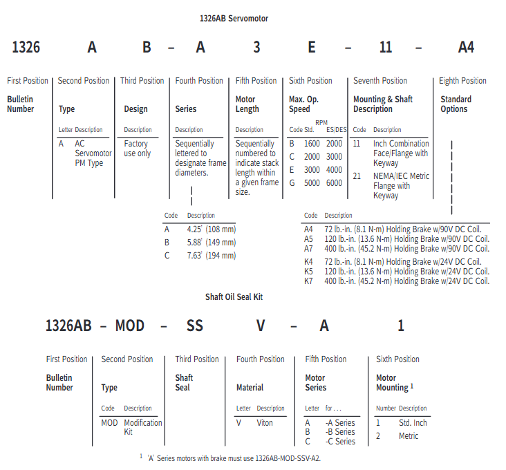
Model interpretation and optional configurations
1. Model coding rules (taking 1326AB-A1G-11-A4 as an example)
Explanation of the meaning of digit codes
1-4 Position 1326 Product Series AC Servo Motor
5th motor type A AC permanent magnet synchronous
6th B frame diameter A=4.25 inches (108mm), B=5.88 inches (149mm), C=7.63 inches (194mm)
The 7th position A is distinguished in alphabetical order based on the stacking length within the same framework (A<B<C<D, with increasing length and greater torque)
8th highest speed G=5000rpm, E=3000rpm, C=2000rpm, B=1600rpm
Installation of positions 9-10 and shaft type 11=NEMA British flange+keyway shaft; 21=IEC metric flange+metric shaft
The 11th to 12th positions of A4 can be selected with attachment A series=90V DC brake (A4=72 lb in/8.1N · m, A5=120 lb in/13.6N · m, A7=400 lb in/45.2N · m); K series=24V DC holding brake (K4/K5/K7 correspond to the same torque)
2. Key optional configurations
Configuration Type Model/Option Code Function Description
The 1326-MOD-BPS brake power supply converts 115V AC to 90V DC and is compatible with A-series brakes. A single unit can drive 4 brakes
Shaft seal kit 1326AB-MOD-SSV-xx on-site installation of Viton material shaft seal, no need to disassemble the motor, compatible with A/B/C series
Feedback component 1326AB-MOD-Vxxxx 4.25-inch (108mm) rotary transformer, supports absolute/fine adjustment format, compatible with 8600GP, IMC and other controllers
Junction box 1326AB-MOD-RJxx axial lead out connector (replacing radial default), maintaining IP65 protection, compatible with A/B/C series
Fan cooling 1326AB-MOD-G3/G4 G3=C2E/C4B motor rear fan; G4=C4B motor "saddle shaped" fan, increasing torque output by 35%
Cable 1326 CPxx (power supply), 1326 CFx (commutation) standard length 15-100 feet, ES version up to 300 feet, only compatible with 1391B-ES/DES driver
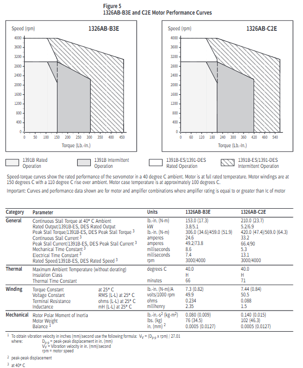
Performance parameters and characteristic curves
1. Core performance parameters (typical model examples)
Motor model: Continuous locked rotor torque (lb in/N · m), peak locked rotor torque (lb in/N · m), rated speed (rpm), rotor moment of inertia (lb in s ²/kg-m ²), rated power (kW), continuous current (A)
1326AB-A1G 16/1.8 48/5.4 5000(1391B)/6000(ES/DES) 0.004/0.0005 0.9 4.5
1326AB-B2E 102/11.5 204/23.0(1391B)/279/31.5(ES/DES) 3000(1391B)/4000(ES/DES) 0.05/0.006 2.5 16.4
1326AB-C3E 310/35.0 568/64.1 3000(1391B)/4000(ES/DES) 0.22/0.024 7.5 49.1
1326AB-C4B 420/47.5 840/94.8(1391B)/989/111.8(ES/DES) 1600(1391B)/2000(ES/DES) 0.29/0.032 5.6 38.2
2. Interpretation of speed torque curve
Curve type: divided into two curves: 1391B controller (regular mode) and 1391B-ES/DES (enhanced mode). The peak torque of the former is twice the continuous torque, while the latter can reach three times, and the highest speed is increased (such as A1G from 5000rpm to 6000rpm).
Operating area:
Rated operating zone: Both the motor and controller shall not exceed the RMS rated value, meeting the continuous operation requirements. The calculation formula is:
Torque (T pa=peak acceleration torque, T ss=steady-state torque, T pd=peak deceleration torque, T r=static torque)
Intermittent operation zone: suitable for acceleration and deceleration scenarios, with a duty cycle RMS torque ≤ rated torque to avoid overheating.
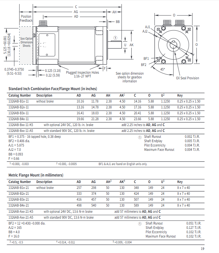
Installation and Dimensional Specifications
1. Mechanical installation requirements
Rail adaptation: The A/B/C series both support 35 × 7.5mm DIN rails (models 199-DR1, etc.). The top hook of the module is locked by rotation after being hooked in, and the grounding resistance should be ≤ 2 Ω (detected through the metal shell of the RS-232 port).
Axial load limit: Radial and axial loads must meet the bearing life requirements (B10 life of 15000 hours). Taking the C series as an example, the maximum radial load at 500rpm is 900lbs, and the axial load is 600lbs (refer to the load curve in Figure 8 for details).
2. Key dimensions (taking imperial flanges as an example)
Series length AD (inches) flange diameter O (inches) shaft diameter U (inches) keyway size (inches) with brake length increase (inches)
A1x-11 8.69 4.38 0.625 0.19×0.19×1.38 2.25
B2x-11 13.16 5.88 1.125 0.25×0.25×1.50 2.25
C3x-11 17.38 7.63 1.375 0.31×0.31×2.00 2.5
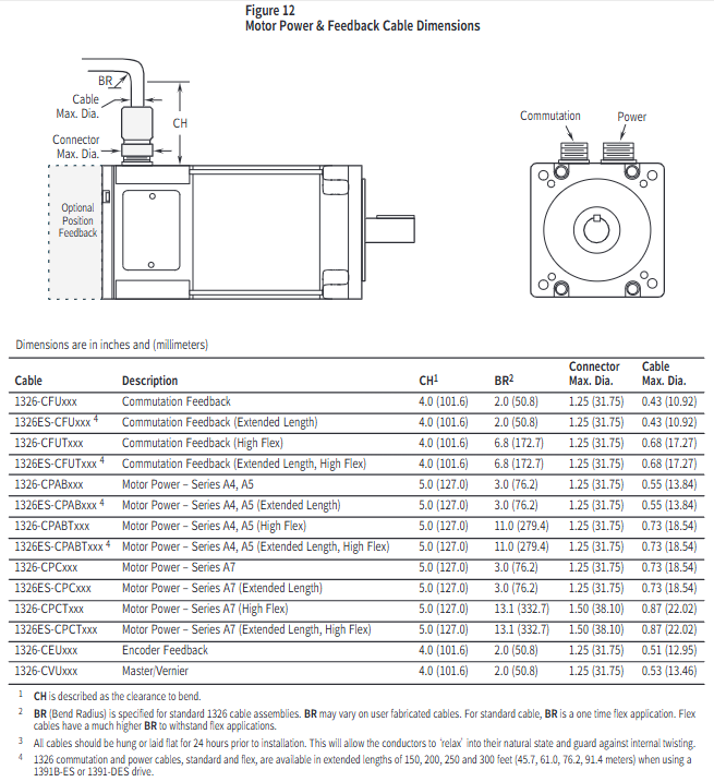
3. Cable installation
Wiring specifications: Power cables (1326-CPABxx) are wired by color (red=PWR, white=CAN_S, blue=CAN_L, black=COM, bare wire=shielded); The feedback cable (1326 CFUxx) needs to distinguish between the switching signal and the encoder signal, and the shielding layer should be grounded separately.
Bending radius: The standard cable has a single bending radius of ≥ 2 inches (50.8mm), and the high flexibility drag chain cable has a bending radius of ≥ 6.8 inches (172.7mm). Before installation, it needs to be laid flat for 24 hours to release internal stress.
Application Selection and Calculation Guide
1. Selection steps
Determine the speed requirement: Calculate the peak speed of the motor based on the mechanical transmission ratio (for example, if the lead screw is 2 inches and the slide table speed is 400ipm, then the motor speed=400/2=200rpm, with a 20% margin to be reserved).
Calculate continuous torque: Taking screw drive as an example based on load type (friction, cutting force, etc.):
T m=6.28 × e 1 × e 2 × G.R. (W 1 × u+Trust) × Lead × 1.1 (W 1=slide weight, u=friction coefficient, Lead=lead screw, e 1/e 2=lead screw/gearbox efficiency, G.R.=transmission ratio, 1.1 is safety factor)
Verify peak torque: Considering acceleration and deceleration requirements, the calculation formula is:
Peak torque (J total=total moment of inertia, Δ rpm=speed change, t accel=acceleration time, T l=load torque)
Match motor parameters: Ensure that the peak speed of the motor is ≥ the calculated value, the continuous torque is ≥ the required value, and the total inertia is ≤ 5 times the motor inertia (to avoid response lag).
2. Typical application calculation example (screw drive)
Known conditions: slide weight of 500lbs, friction coefficient of 0.05, lead screw of 1 inch, transmission ratio of 1:1, efficiency of 0.9, acceleration time of 0.5 seconds, and speed from 0 to 1000rpm.
Continuous torque calculation: T m=6.28 × 0.9 × 1 (500 × 0.05) × 1 × 1.1 ≈ 5.0 lb in, select A1G (16 lb in) to meet the demand.
Peak torque calculation: Total inertia=sliding table inertia (386500 × (6.281) 2 ≈ 0.0033 lb in ²)+motor inertia (0.004)=0.0073, peak torque=9.6 × 0.5 0.0073 × 1000+0 ≈ 1.52 lb in, which is less than the A1G peak value of 48 lb in and meets the requirements.
Maintenance and safety precautions
Thermal protection: The maximum temperature of the motor winding is 150 ° C (H-class insulation). When the ambient temperature exceeds 40 ° C, it needs to be de rated for use (for every 10 ° C increase, the torque is de rated by 10%).
Brake usage: The brake is only used for static load holding (switching ≤ 90 times per hour) and cannot be used for positioning or frequent braking. The 24V DC brake requires the user to provide their own power supply (0.88-1.2A).
Protection level: IP65 is only applicable to situations with shaft seals and no external feedback/fan. Additional protection is required in humid or corrosive environments.
Troubleshooting: When triggering the thermal switch, it is necessary to first investigate issues such as excessive load and poor heat dissipation. Resetting requires waiting for the winding temperature to drop to 90-100 ° C.
- YOKOGAWA
- Reliance
- ADVANCED
- SEW
- ProSoft
- WATLOW
- Kongsberg
- FANUC
- VSD
- DCS
- PLC
- man-machine
- Covid-19
- Energy and Gender
- Energy Access
- Renewable Integration
- Energy Subsidies
- Energy and Water
- Net zero emission
- Energy Security
- Critical Minerals
- A-B
- petroleum
- Mine scale
- Sewage treatment
- cement
- architecture
- Industrial information
- New energy
- Automobile market
- electricity
- Construction site
- HIMA
- ABB
- Rockwell
- Schneider Modicon
- Siemens
- xYCOM
- Yaskawa
- Woodward
- BOSCH Rexroth
- MOOG
- General Electric
- American NI
- Rolls-Royce
- CTI
- Honeywell
- EMERSON
- MAN
- GE
- TRICONEX
- Control Wave
- ALSTOM
- AMAT
- STUDER
- KONGSBERG
- MOTOROLA
- DANAHER MOTION
- Bentley
- Galil
- EATON
- MOLEX
- Triconex
- DEIF
- B&W
- ZYGO
- Aerotech
- DANFOSS
- KOLLMORGEN
- Beijer
- Endress+Hauser
- schneider
- Foxboro
- KB
- REXROTH
- YAMAHA
- Johnson
- Westinghouse
- WAGO
- TOSHIBA
- TEKTRONIX
- BENDER
- BMCM
- SMC
- HITACHI
- HIRSCHMANN
- XP POWER
- Baldor
- Meggitt
- SHINKAWA
- Other Brands
- UniOP
- KUKA
- IBA
- Beckhoff
- ADLINK
-
Beckhoff EP9224-0037 - 4-Channel Power Distribution Box EtherCAT
-
Beckhoff CX2900-0026 - Solid State Flash Memory Card 20GB CFast
-
Beckhoff BK7500 - SERCOS Interface Fieldbus Bus Coupler Terminal
-
Beckhoff Ep2328-0002 - 4-Channel Input 4-Channel Output EtherCAT Box IP67
-
Beckhoff CX1020-0111 - Controller Kit Combo Interface Modules
-
B&R X20AI2237 - X20 System Analog Input Interface Module
-
Beckhoff CP2221-0010 - Multi-Touch Built-In Panel PC Touchscreen
-
Beckhoff CX1500-M310 - Fieldbus Master Interface Module 24V
-
Beckhoff CX2100-0904 - Power Charging Module Smart UPS Extension
-
Beckhoff CP3918-0000 - Multi-Touch Control Panel 18.5-Inch Monitor
-
Beckhoff CP2915-0000 - 15-Inch Multi-Touch Built-In Control Panel
-
Beckhoff CP7037-1027 - HMI Industrial Control Panel Built-In PC
-
Beckhoff EL3152 - 2-Channel Analog Input Terminal 4-20mA EtherCAT
-
Beckhoff CP6607-0000-0020 - 5.7-Inch Built-In Panel PC HMI Touch
-
Beckhoff EJ1809-0000 - 16-Channel Digital Input Pluggable Signal Level Terminal
-
Beckhoff AM8563-0N10-0000 - Synchronous Servo Motor
-
Beckhoff AX2006-S60600-520 - Compact Servo Drive Inverter
-
Beckhoff AM8053-0K20-0000 - Servo Motor with Planetary Gearbox AG3210
-
Beckhoff AM8042-0FH1-0000 - Synchronous Servo Motor
-
Rexroth R911338600 - IndraControl V HMI Terminal Beckhoff PCI Card FC9002
-
Beckhoff AX5125-0000 - 3 Phase Industrial Servo Drive 1000Hz
-
Beckhoff EP2328-0002 - 4-Channel Digital Input 4-Channel Output EtherCAT Box
-
B&R 7CP476-02 - System 2005 RTD CPU Module 3IF681.86 Interface
-
Beckhoff AX8620-0000-0000 - Power Supply Module Axis Drive System
-
Beckhoff CX1010-0111 - PLC Module CPU Controller 24V
-
Beckhoff AM8043-0H10-0000 - Synchronous Servo Motor
-
Beckhoff C6240-1009 - Control Cabinet Industrial PC Mainframe
-
Beckhoff BX8000-0000 - Bus Terminal Controller HW 4.4 Standalone
-
Beckhoff CP7721-1089-0020 - 12.1-Inch Touch Screen HMI Panel PC
-
Beckhoff CP7132-0001 - Industrial Built-In Panel PC Screen
-
Beckhoff CP2912-0010 - Multi-Touch Built-In Control Panel Display
-
Beckhoff CP2915-0000 - 15-Inch Multi-Touch Built-In Control Panel
-
Beckhoff AM8532-1EN0-0000 - Synchronous Servo Motor
-
Beckhoff AX5203-0000 - 2-Channel Digital Compact Servo Drive
-
Beckhoff CX2020-0141 - Embedded PC Core CPU Module
-
Beckhoff CP6832-0002-0010 - Built-In Industrial Control Panel Display
-
Beckhoff CX5020-0112 - Embedded PC CPU Control Module
-
Beckhoff CX5140-0175 - 4GB Embedded PC CPU Unit 24V
-
Beckhoff EL3681-0030 - Digital Multimeter Calibration Terminal EtherCAT
-
Beckhoff CP7201-1000-0000 - Industrial PC Touch Screen HMI Monitor
-
Beckhoff CP7232-1001-0000 - Industrial Panel PC Touch Screen
-
Beckhoff C6930-1032-0040 - Control Cabinet Industrial PC System
-
Beckhoff AX5125-0000 - 3 Phase Industrial Servo Drive 1000Hz
-
Beckhoff CP3916-1424-0000 - Multi-Touch Built-In Control Panel
-
B&R 1900071142 - Lemoine Fieldbus Communication Interface Module
-
Beckhoff EL2872 - 16-Channel Ribbon Cable Digital Output Terminal
-
Beckhoff CX2030-0120 - Embedded PC CPU Base Module Controller
-
Beckhoff CP3919-0000 - 19-Inch Multi-Touch Control Panel Touchscreen
-
Beckhoff AX5101-0000-0202 - Servo Driver Compact Intelligent Drive 180V
-
Beckhoff CX5130-0135 - Embedded PC Controller Module
-
Beckhoff CP3719-1061-0010 - Multi-Touch Panel PC Outer Housing Enclosure
-
Beckhoff CP3919-1033-0000 - 19-Inch Touch Industrial Panel Keyboard
-
Beckhoff CX5020-0111 - Embedded PC PLC CPU Module
-
Beckhoff FC5102-0000 - 2-Channel CANopen PCI Control Board Card
-
Beckhoff CX9001-1101 - Embedded PC CPU Network I/O System Module
-
Beckhoff CX1100-0920 - Smart Position Sensor Interface Module
-
B&R 4P3040.01-490 - Operator Panel PLC Interface Communication Module
-
Beckhoff CP2612-0000 - Dual-Touch Built-In Panel PC HMI
-
Beckhoff CP7002-1043-0010 - Touchscreen Display HMI Panel Terminal
-
Beckhoff CX9020-0115 - Embedded PC Controller Module
-
Beckhoff CX5140-0155 - 4GB Embedded PC CPU Module Die Industry
-
B&R 7DI435.7 - System 2005 Universal Digital Input Output Module
-
Bihl+Wiedemann BWU1568 - AS-i Master to Profibus Gateway Module
-
Beckhoff C6920-0070 - Control Cabinet Industrial PC 8GB Win 10
-
B&R X20AI2322 - 2-Channel Temperature Analog Input Module
-
Beckhoff CP2912-0000 - 12-Inch Touchscreen Display Monitor Screen
-
Beckhoff CP6022-1001-0010 - 15-Inch Built-In Control Panel
-
Beckhoff AM8031-0D10-0000 - Synchronous Servo Motor
-
Beckhoff CX5010-0111 - Embedded PC Controller CPU Module
-
Beckhoff CP7232-1000-0000 - Industrial Panel PC Touch Display Screen
-
Beckhoff CP7802-0011-0000 - 15-Inch Industrial Touchscreen Control Panel
-
Beckhoff C6320 - Control Cabinet Industrial PC
-
Beckhoff CX1030-0012 - Basic CPU Module Windows CE 6.0
-
Beckhoff CP2919-0000 - Installation Multi-Touch Control Panel
-
Beckhoff CX1020-0000 - Controller Set Stack System Pack
-
B&R 3DO480.6 - System 2005 Digital Output Module
-
Beckhoff EL3101 - 1-Channel Analog Input Terminal Differential +/-10V
-
Beckhoff AX8108-0200-0000 - Axis Feed Module Servo Drive
-
Beckhoff CP7802-1241-0010 - 15-Inch Industrial Touchscreen Control Panel
-
Beckhoff FC2002-0000 - 2-Channel Lightbus Data Acquisition PCI Card
-
Beckhoff CX5120-0155 - 2GB Embedded PC Intel Atom Controller
-
Beckhoff Cx9020-0111 - 1GB Basic CPU Module Embedded PC
-
Beckhoff CP6901-0001-0000 - 12-Inch Economy Built-In Control Panel
-
Beckhoff CX9020-0111 - Embedded PC CPU Basic Module
-
Beckhoff CX5130-0100 - 4GB Embedded PC CPU Module
-
Beckhoff CP2715-0010 - Multi-Touch Built-In Panel PC
-
Beckhoff CX2033-0175 - Embedded PC CPU Module Core i7
-
Beckhoff CP7201-1000-0000 - 12-Inch Touchscreen Panel PC AMAT Green Box
-
Beckhoff EL4038 - 8-Channel Analog Output Terminal 0-10V EtherCAT
-
Beckhoff CP6802-0000-0000 - Built-In Control Panel HMI Screen
-
Beckhoff CP6500-1012-0060 - Control Cabinet PC Interface Unit
-
Beckhoff FC5202-0000 - 2-Channel DeviceNet Master PCI Interface Card
-
Beckhoff CP6606-0001-0020 - 7-Inch Economy Panel PC Touch
-
Beckhoff CP2921-0010 - Multi-Touch Integrated Control Panel Display
-
Beckhoff CP7802-0001-0010 - 15-Inch Touch Screen Control Panel HMI
-
Beckhoff C6920-0050 - Control Cabinet Industrial PC
-
Beckhoff BK9105 - EtherNet/IP Bus Coupler Network Interface
-
Beckhoff 31 Modules - Bus Terminal Slice I/O Lot Assortment
-
Beckhoff CX2020-0120 - Embedded PC Basic CPU Module 8GB CFast Card
-
Beckhoff CP7001-0000 - HMI Control Panel Touch Screen
-
B&R 7EX484.50-1 - System 2005 Controller Base Module Slots
-
Beckhoff EK1322 - 2-Port EtherCAT P Extension Feed-In Terminal
-
Beckhoff CP6606-0001-0020 - 7-Inch Single-Touch Economy Panel PC
-
Beckhoff CP6607-0001-0000 - Economy Installation Operator Panel PC 5.7-Inch
-
Beckhoff AX5103-0000-0200 - Digital Compact Servo Driver 3 Phase
-
Beckhoff CP7802-0001-0010 - 15-Inch Touch Screen Control Panel
-
Beckhoff AX8620 - Power Supply Module Axis System
-
Beckhoff CX2030-0121 - Embedded PC Controller Module
-
Beckhoff CP6606-0001-0020 - 7-Inch Economy Panel PC Touch Screen
-
Beckhoff CX2030-0121 - Embedded PC CPU Module Windows Standard 7
-
Beckhoff BX3100-0000 - PROFIBUS DP Bus Terminal Controller
-
Beckhoff CX1020-0000 - Controller Set with Power Supply Unit
-
Beckhoff EK1100 - EtherCAT Coupler Terminal Module Set
-
Beckhoff CP7002-1043-0010 - HMI Display Panel with Control Panel Bracket
-
Beckhoff AM8031-0D10-0000 - Synchronous Servo Motor
-
Beckhoff CX5130-0175 - Embedded PC 4GB RAM Controller
-
Beckhoff CX5130-0155 - Embedded PC Automation Controller
-
Beckhoff C6930-0010 - Control Cabinet Industrial PC Core Duo
-
Beckhoff CP3924-0000 - Multi-Touch Control Panel Display
-
Beckhoff AM8023-0F20-0000 - Synchronous Servo Motor
-
B&R KL3362 - Bus Terminal Thermocouple Input Module
-
Beckhoff AL2006-0000-0000 - Linear Servo Motor Three Phase
-
Beckhoff CX5140-0155 - Embedded PC CPU Controller Module
-
Beckhoff FC9002 - Ethernet PCI Network Interface Card
-
Beckhoff CP7203-0021-0040 - Built-In Panel PC 19-Inch Touch Screen
-
Beckhoff C6930-0020 - Control Cabinet Industrial PC HDD CF Card
-
Beckhoff CX2900-0033 - Memory Card CFast Storage
-
Beckhoff CP6201-0001-0020 - Built-In Panel PC Display

K-JIANG

Add: Jimei North Road, Jimei District, Xiamen, Fujian, China
Tell:+86-15305925923