
K-WANG


Allen Bradley 1336 IMPACT AC Inverter
Allen Bradley 1336 IMPACT AC Inverter
Product Overview and Core Features
1. Product positioning and applicable scenarios
1336 IMPACT frequency converter is a microprocessor based field oriented control (FOC) AC frequency converter using Force technologies ™ Technology, focusing on low-cost independent applications, suitable for scenarios such as machine tools, production lines, and material handling that require precise speed regulation, supports speed and torque control of asynchronous motors, and is compatible with multiple feedback devices and communication protocols.
2. Core standard features
Performance and Control:
High precision digital speed loop and current loop, supporting 0-250Hz constant torque output, some configurations can achieve 400% motor current (short-term overload).
Supports multiple braking methods: dynamic braking, DC braking, magnetic flux braking, and bus voltage regulation, adapting to different load deceleration requirements.
Feedback and Interface:
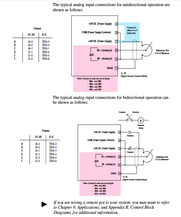
Standard configuration includes 2 ± 10V analog inputs, 2 ± 10V analog outputs, and 1 4-20mA input/output. The 12 bit resolution ensures signal accuracy.
Support encoder feedback (requires L Option board), compatible with 12V/5V differential output encoder, up to 100kHz pulse input, achieving high-precision speed/position control.
Protection and reliability:
Built in motor overload protection (I ² T), inverter overload protection, overcurrent, overvoltage, undervoltage, ground fault, overheating and other multiple protections.
32 fault queues and 32 warning queues, with timestamps and fault markers for easy problem tracing; Non volatile memory (EE) stores parameters and configurations without loss during power outages.
Communication and Expansion:
Supports SCANPort communication and can connect to HIM (Human Interface Module), GPT (Graphics Programming Terminal), and 1203 series gateway modules (such as DeviceNet, RS-232/485).
Optional L Option board extension control input, supports TTL/24V AC/DC/115V AC interfaces, and some models come with encoder feedback interfaces.
Model Interpretation and Framework Classification
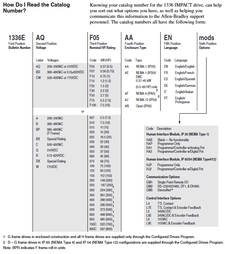
1. Model coding rules (taking 1336E-AQF05-AA-EN as an example)
Explanation of the meaning of digit codes
1-4 Position 1336E Product Series 1336 IMPACT AC Inverter
Position 5-6 AQ voltage level AQ=200-240VAC/310VDC; BR=380-480VAC/513-620VDC; CW=500-600VAC/775VDC
The rated power of F05 in positions 7-9 is 0.37kW (0.5HP); F07=0.56kW (0.75HP); F10=0.75kW (1HP), Repeat this process until 800C=597kW (800HP)
AA protection level AA=NEMA 1 (IP20) for positions 10-11; AE=NEMA 1 (IP20)/EMC (0.37-45kW dedicated); AF=NEMA 4 (IP65); AJ=NEMA 12 (IP54)
The 12th and 13th digits of EN language are English/English; FR=English/French; ES=English/Spanish; DE=English/German, etc
Subsequent mod options include HIM type (such as HA1 with analog potentiometer), communication module (such as GM5=DeviceNet), and L Option board (such as L8E=24V AC/DC+encoder)
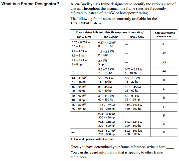
2. Frame classification and power correspondence
The framework is divided by size and power, and the installation and wiring requirements for different frameworks are different. The core correspondence is as follows:
Framework Model 200-240V Power Range 380-480V Power Range 500-600V Power Range Key Features
A1 0.37-0.75kW (0.5-1HP) 0.37-1.2kW (0.5-1.5HP) - miniaturization, suitable for light loads
A2 1.2-1.5kW (1.5-2HP) 1.5-2.2kW (2-3HP) - Compact, supporting basic analog control
A3 2.2-3.7kW (3-5HP) 3.7kW (5HP) - Medium load, optional encoder feedback
A4-5.5-7.5kW (7.5-10HP) 0.75-7.5kW (1-10HP) with cooling fan, supporting dynamic braking
B 5.5-11kW (7.5-15HP) 15-22kW (20-30HP) 11-15kW (15-20HP) modular design, supporting multiple communication interfaces
C-H 30-75kW (40-100HP) 45-597kW (60-800HP) high power, requiring external reactors, H frame with independent cooling system
Installation and wiring specifications
1. General safety requirements
Static protection: The module contains ESD sensitive components, and a grounding wristband should be worn during operation. Refer to Rockwell document 8000-4.5.2 "Guidelines for Preventing Static Damage".
Power off operation: Before installation, all power sources of the frequency converter (including AC input, DC bus, control power) must be disconnected to avoid electric shock or component damage.
Cable requirements: Power cables must comply with NEC/VDE standards, and it is recommended to use shielded twisted pair cables (such as Belden 8760) for control cables to avoid parallel laying with high-power cables and reduce interference.
2. Key points for exclusive installation of the framework
(1) A1-A4 frame (low power)
Rail installation: Suitable for 35 × 7.5mm DIN rails, with hooks inserted and locked by rotation. The grounding resistance should be ≤ 2 Ω (detected through the metal shell of the RS-232 port).
Wiring terminal: TB1 is the power terminal (R/L1, S/L2, T/L3 input; U/T1, V/T2, W/T3 outputs), TB4/TB7/TB10 are control terminals, supporting analog I/O, pulse input, and relay output.
Input protection: Users need to provide their own fuses. For example, models with 200-240V/0.37kW require 6A Class CC fuses (North America) or 6A gG fuses (Europe).
(2) B-H framework (high power)
Fixed method: B-C frame can be installed on rails, D-H frame needs to be fixed with bolts, and reserved heat dissipation space (top/sides ≥ 152.4mm, bottom ≥ 101.6mm).
Wiring requirements: The D-H frame adopts bolt type terminals and requires dedicated wiring terminals (such as T&B COLOR KEYED) ®), The maximum wire diameter supported is 600MCM (253mm ²), and the torque must comply with the specifications (such as 23N · m for the H frame).
Cooling system: F-H frame with forced cooling fan, fan voltage needs to be confirmed (200-240V/380-480V), H frame needs independent air duct, air volume ≥ 2600CFM.
3. Key wiring specifications
Power wiring:
AC input: R/L1, S/L2, T/L3, requiring input fuses/circuit breakers (such as 140-MN-0250 circuit breaker for 380-480V/0.37kW).
Motor output: U/T1, V/T2, W/T3, cable length must meet the requirements (e.g. maximum 500m at 125Kbps, 100m at 500Kbps), and output reactors need to be added for long distances.
Control wiring:
Analog input: ± 10V input requires differential wiring, and the shielding layer is grounded at one end (TE terminal); 4-20mA input impedance of 130 Ω, maximum load of 750 Ω.
Encoder wiring (L Option board): A/A non, B/B non signal differential access,+12V power supply (maximum 200mA), shielding layer grounded.
Grounding requirements:
The safety grounding (PE terminal) requires copper wire with a wire diameter of ≥ 1.5mm ² (16AWG) and a grounding impedance of ≤ 4 Ω.
The control signal grounding (TE terminal) is independent of the power grounding to avoid common ground interference.
System startup and parameter configuration
1. Preparation before startup
Hardware inspection: Confirm correct wiring (no AC input/output terminals, no short circuits), clean fan/heat sink, and securely install encoder (if any).
Tool preparation: HIM module (default connection to SCANPort 1), digital multimeter (measuring input voltage, within ± 10% of rated value), insulation resistance meter (measuring motor insulation, ≥ 1M Ω).
Parameter recording: Record the frequency converter model, motor nameplate data (power, voltage, current, speed, number of poles), and encoder PPR value for rapid debugging in the future.
2. Quick start process (via HIM)
(1) Power on and HIM operation
After powering on, the HIM displays the startup interface. Press any key to enter "Choose Mode" and select "Start Up".
Quick Motor Tune:
Select 'Enter Nameplate Motor Data' and enter the motor HP, voltage, current, etc Hz、 Speed and number of poles.
If using an encoder, select "Encoder" and enter the PPR value; Choose the braking method (dynamic braking/magnetic flux braking, etc.).
Press the START button to test the direction of motor rotation. If it is reversed, adjust the motor phase sequence; Run self-tuning (inductance, resistance, flux current, inertia test), and display "Tune Complete" after completion.
Config Digital Section:
Configure relay output (such as setting Relay 1 to "At Speed" and threshold to 95% rated speed).
Configure L Option mode (such as mode 5 supporting MOP manual potentiometer control) and stop type (coasting/ramp/current limit stop).
Configure Analog Section:
Link speed reference (e.g. Analog In1 link Speed Ref 1, Scale set to 2.0 to achieve ± 10V corresponding to ± 100% speed).
Configure analog output (such as Analog Out1 linked to Motor Speed, Scale set to 0.5 to achieve ± 100% speed corresponding to ± 5V output).
3. Core parameter description
Parameter classification, key parameter functions, and default values
Motor nameplate Nameplate HP (2) The rated power of the motor should be consistent with the nameplate
Motor Poles (7) motor pole count, default 4 poles
Speed control Speed Ref 1 (29) Main speed reference, default 0rpm
Accel Time 1 (42) acceleration time, default 5.0 seconds
Decel Time 1 (44) Deceleration time, default 5.0 seconds
Feedback and Protection Fdbk Device Type (64) Feedback Device Type, 0=No Encoder, 2=Encoder
Motor Overload% (26) motor overload threshold, default 115%
Communication and Expansion L Option Mode (116) L Option Working Mode, default 1 (disabled)
SP An In1 Select (133) SCANPort analog input selection, default 1 (HIM)
Functional applications and advanced controls
1. Basic control functions
Start stop and speed regulation:
Local control: Use the START/STOP button on HIM to start and stop, and the Up/Down button to adjust the speed; Remote control: Speed regulation through analog input (such as 4-20mA) or SCANPort signal.
Jog Speed 1 (38) is set to 10% rated speed, triggering Jog input to achieve jog control.
Braking control:
Dynamic braking: An external braking resistor is required, with Bus/Brake Options (13) set to bit10=1 and Regen Power Lim (76) set to 50% (adjusted according to the resistor capacity).
DC Braking: The DC Brake Current (79) is set to 30% of the rated current, and the DC Brake Time (80) is set to 2 seconds, suitable for rapid shutdown.
2. Advanced functional applications
(1) Speed Profiling
Function: Implement multi-stage speed control through 16 programmable steps, supporting switching between time, encoder counting, and digital input trigger steps.
Configuration: L Option mode 31/32 is required, with Step Speed (e.g. Step 1=400rpm), Step Type (1=time triggered, 3=encoder triggered), Step Value (e.g. 10 seconds/1000 counts) set, and End Action set to "loop" or "zero".
(2) Torque control
Function: Switch to torque mode (Spd/Trq Mode Sel (68)=1), set torque reference (0-100% rated torque) through Torque Ref 1 (69).
Application: Suitable for winding and tension control scenarios, requiring encoder feedback to ensure torque accuracy, Pos/Neg Torque Lim (74/75) limits maximum torque.
(3) Flying Start
Function: Start the frequency converter when the motor rotates to avoid current shock, suitable for restarting fans and pumps after sudden power failure.
Configuration: FStart Select (216)=2, FStart Speed (217) is set to the estimated speed (such as 800rpm), and the frequency converter automatically searches and synchronizes the speed after startup.
3. Communication configuration (SCAnport/DeviceNet)
SCAnport communication:
Supports up to 6 SCAnport devices, with HIM default to SCAnport 1 and gateway modules (such as 1203-GM5) connected to SCAnport 6.
Configure SP Enable Mask (124) to allow device control permissions, such as allowing SCANPort 2 to send start stop signals.
DeviceNet communication:
The 1203-GM5 card needs to be installed, and the node address (SW2-1~6, binary encoding) and baud rate (SW2-7~8, default 125Kbps) need to be set.
Create an EDS file through DeviceNet Manager, map I/O data (such as input=motor status, output=speed reference), and set the polling rate to 50ms.
- YOKOGAWA
- Reliance
- ADVANCED
- SEW
- ProSoft
- WATLOW
- Kongsberg
- FANUC
- VSD
- DCS
- PLC
- man-machine
- Covid-19
- Energy and Gender
- Energy Access
- Renewable Integration
- Energy Subsidies
- Energy and Water
- Net zero emission
- Energy Security
- Critical Minerals
- A-B
- petroleum
- Mine scale
- Sewage treatment
- cement
- architecture
- Industrial information
- New energy
- Automobile market
- electricity
- Construction site
- HIMA
- ABB
- Rockwell
- Schneider Modicon
- Siemens
- xYCOM
- Yaskawa
- Woodward
- BOSCH Rexroth
- MOOG
- General Electric
- American NI
- Rolls-Royce
- CTI
- Honeywell
- EMERSON
- MAN
- GE
- TRICONEX
- Control Wave
- ALSTOM
- AMAT
- STUDER
- KONGSBERG
- MOTOROLA
- DANAHER MOTION
- Bentley
- Galil
- EATON
- MOLEX
- Triconex
- DEIF
- B&W
- ZYGO
- Aerotech
- DANFOSS
- KOLLMORGEN
- Beijer
- Endress+Hauser
- schneider
- Foxboro
- KB
- REXROTH
- YAMAHA
- Johnson
- Westinghouse
- WAGO
- TOSHIBA
- TEKTRONIX
- BENDER
- BMCM
- SMC
- HITACHI
- HIRSCHMANN
- XP POWER
- Baldor
- Meggitt
- SHINKAWA
- Other Brands
- UniOP
- KUKA
- IBA
- Beckhoff
- ADLINK
-
Beckhoff EP9224-0037 - 4-Channel Power Distribution Box EtherCAT
-
Beckhoff CX2900-0026 - Solid State Flash Memory Card 20GB CFast
-
Beckhoff BK7500 - SERCOS Interface Fieldbus Bus Coupler Terminal
-
Beckhoff Ep2328-0002 - 4-Channel Input 4-Channel Output EtherCAT Box IP67
-
Beckhoff CX1020-0111 - Controller Kit Combo Interface Modules
-
B&R X20AI2237 - X20 System Analog Input Interface Module
-
Beckhoff CP2221-0010 - Multi-Touch Built-In Panel PC Touchscreen
-
Beckhoff CX1500-M310 - Fieldbus Master Interface Module 24V
-
Beckhoff CX2100-0904 - Power Charging Module Smart UPS Extension
-
Beckhoff CP3918-0000 - Multi-Touch Control Panel 18.5-Inch Monitor
-
Beckhoff CP2915-0000 - 15-Inch Multi-Touch Built-In Control Panel
-
Beckhoff CP7037-1027 - HMI Industrial Control Panel Built-In PC
-
Beckhoff EL3152 - 2-Channel Analog Input Terminal 4-20mA EtherCAT
-
Beckhoff CP6607-0000-0020 - 5.7-Inch Built-In Panel PC HMI Touch
-
Beckhoff EJ1809-0000 - 16-Channel Digital Input Pluggable Signal Level Terminal
-
Beckhoff AM8563-0N10-0000 - Synchronous Servo Motor
-
Beckhoff AX2006-S60600-520 - Compact Servo Drive Inverter
-
Beckhoff AM8053-0K20-0000 - Servo Motor with Planetary Gearbox AG3210
-
Beckhoff AM8042-0FH1-0000 - Synchronous Servo Motor
-
Rexroth R911338600 - IndraControl V HMI Terminal Beckhoff PCI Card FC9002
-
Beckhoff AX5125-0000 - 3 Phase Industrial Servo Drive 1000Hz
-
Beckhoff EP2328-0002 - 4-Channel Digital Input 4-Channel Output EtherCAT Box
-
B&R 7CP476-02 - System 2005 RTD CPU Module 3IF681.86 Interface
-
Beckhoff AX8620-0000-0000 - Power Supply Module Axis Drive System
-
Beckhoff CX1010-0111 - PLC Module CPU Controller 24V
-
Beckhoff AM8043-0H10-0000 - Synchronous Servo Motor
-
Beckhoff C6240-1009 - Control Cabinet Industrial PC Mainframe
-
Beckhoff BX8000-0000 - Bus Terminal Controller HW 4.4 Standalone
-
Beckhoff CP7721-1089-0020 - 12.1-Inch Touch Screen HMI Panel PC
-
Beckhoff CP7132-0001 - Industrial Built-In Panel PC Screen
-
Beckhoff CP2912-0010 - Multi-Touch Built-In Control Panel Display
-
Beckhoff CP2915-0000 - 15-Inch Multi-Touch Built-In Control Panel
-
Beckhoff AM8532-1EN0-0000 - Synchronous Servo Motor
-
Beckhoff AX5203-0000 - 2-Channel Digital Compact Servo Drive
-
Beckhoff CX2020-0141 - Embedded PC Core CPU Module
-
Beckhoff CP6832-0002-0010 - Built-In Industrial Control Panel Display
-
Beckhoff CX5020-0112 - Embedded PC CPU Control Module
-
Beckhoff CX5140-0175 - 4GB Embedded PC CPU Unit 24V
-
Beckhoff EL3681-0030 - Digital Multimeter Calibration Terminal EtherCAT
-
Beckhoff CP7201-1000-0000 - Industrial PC Touch Screen HMI Monitor
-
Beckhoff CP7232-1001-0000 - Industrial Panel PC Touch Screen
-
Beckhoff C6930-1032-0040 - Control Cabinet Industrial PC System
-
Beckhoff AX5125-0000 - 3 Phase Industrial Servo Drive 1000Hz
-
Beckhoff CP3916-1424-0000 - Multi-Touch Built-In Control Panel
-
B&R 1900071142 - Lemoine Fieldbus Communication Interface Module
-
Beckhoff EL2872 - 16-Channel Ribbon Cable Digital Output Terminal
-
Beckhoff CX2030-0120 - Embedded PC CPU Base Module Controller
-
Beckhoff CP3919-0000 - 19-Inch Multi-Touch Control Panel Touchscreen
-
Beckhoff AX5101-0000-0202 - Servo Driver Compact Intelligent Drive 180V
-
Beckhoff CX5130-0135 - Embedded PC Controller Module
-
Beckhoff CP3719-1061-0010 - Multi-Touch Panel PC Outer Housing Enclosure
-
Beckhoff CP3919-1033-0000 - 19-Inch Touch Industrial Panel Keyboard
-
Beckhoff CX5020-0111 - Embedded PC PLC CPU Module
-
Beckhoff FC5102-0000 - 2-Channel CANopen PCI Control Board Card
-
Beckhoff CX9001-1101 - Embedded PC CPU Network I/O System Module
-
Beckhoff CX1100-0920 - Smart Position Sensor Interface Module
-
B&R 4P3040.01-490 - Operator Panel PLC Interface Communication Module
-
Beckhoff CP2612-0000 - Dual-Touch Built-In Panel PC HMI
-
Beckhoff CP7002-1043-0010 - Touchscreen Display HMI Panel Terminal
-
Beckhoff CX9020-0115 - Embedded PC Controller Module
-
Beckhoff CX5140-0155 - 4GB Embedded PC CPU Module Die Industry
-
B&R 7DI435.7 - System 2005 Universal Digital Input Output Module
-
Bihl+Wiedemann BWU1568 - AS-i Master to Profibus Gateway Module
-
Beckhoff C6920-0070 - Control Cabinet Industrial PC 8GB Win 10
-
B&R X20AI2322 - 2-Channel Temperature Analog Input Module
-
Beckhoff CP2912-0000 - 12-Inch Touchscreen Display Monitor Screen
-
Beckhoff CP6022-1001-0010 - 15-Inch Built-In Control Panel
-
Beckhoff AM8031-0D10-0000 - Synchronous Servo Motor
-
Beckhoff CX5010-0111 - Embedded PC Controller CPU Module
-
Beckhoff CP7232-1000-0000 - Industrial Panel PC Touch Display Screen
-
Beckhoff CP7802-0011-0000 - 15-Inch Industrial Touchscreen Control Panel
-
Beckhoff C6320 - Control Cabinet Industrial PC
-
Beckhoff CX1030-0012 - Basic CPU Module Windows CE 6.0
-
Beckhoff CP2919-0000 - Installation Multi-Touch Control Panel
-
Beckhoff CX1020-0000 - Controller Set Stack System Pack
-
B&R 3DO480.6 - System 2005 Digital Output Module
-
Beckhoff EL3101 - 1-Channel Analog Input Terminal Differential +/-10V
-
Beckhoff AX8108-0200-0000 - Axis Feed Module Servo Drive
-
Beckhoff CP7802-1241-0010 - 15-Inch Industrial Touchscreen Control Panel
-
Beckhoff FC2002-0000 - 2-Channel Lightbus Data Acquisition PCI Card
-
Beckhoff CX5120-0155 - 2GB Embedded PC Intel Atom Controller
-
Beckhoff Cx9020-0111 - 1GB Basic CPU Module Embedded PC
-
Beckhoff CP6901-0001-0000 - 12-Inch Economy Built-In Control Panel
-
Beckhoff CX9020-0111 - Embedded PC CPU Basic Module
-
Beckhoff CX5130-0100 - 4GB Embedded PC CPU Module
-
Beckhoff CP2715-0010 - Multi-Touch Built-In Panel PC
-
Beckhoff CX2033-0175 - Embedded PC CPU Module Core i7
-
Beckhoff CP7201-1000-0000 - 12-Inch Touchscreen Panel PC AMAT Green Box
-
Beckhoff EL4038 - 8-Channel Analog Output Terminal 0-10V EtherCAT
-
Beckhoff CP6802-0000-0000 - Built-In Control Panel HMI Screen
-
Beckhoff CP6500-1012-0060 - Control Cabinet PC Interface Unit
-
Beckhoff FC5202-0000 - 2-Channel DeviceNet Master PCI Interface Card
-
Beckhoff CP6606-0001-0020 - 7-Inch Economy Panel PC Touch
-
Beckhoff CP2921-0010 - Multi-Touch Integrated Control Panel Display
-
Beckhoff CP7802-0001-0010 - 15-Inch Touch Screen Control Panel HMI
-
Beckhoff C6920-0050 - Control Cabinet Industrial PC
-
Beckhoff BK9105 - EtherNet/IP Bus Coupler Network Interface
-
Beckhoff 31 Modules - Bus Terminal Slice I/O Lot Assortment
-
Beckhoff CX2020-0120 - Embedded PC Basic CPU Module 8GB CFast Card
-
Beckhoff CP7001-0000 - HMI Control Panel Touch Screen
-
B&R 7EX484.50-1 - System 2005 Controller Base Module Slots
-
Beckhoff EK1322 - 2-Port EtherCAT P Extension Feed-In Terminal
-
Beckhoff CP6606-0001-0020 - 7-Inch Single-Touch Economy Panel PC
-
Beckhoff CP6607-0001-0000 - Economy Installation Operator Panel PC 5.7-Inch
-
Beckhoff AX5103-0000-0200 - Digital Compact Servo Driver 3 Phase
-
Beckhoff CP7802-0001-0010 - 15-Inch Touch Screen Control Panel
-
Beckhoff AX8620 - Power Supply Module Axis System
-
Beckhoff CX2030-0121 - Embedded PC Controller Module
-
Beckhoff CP6606-0001-0020 - 7-Inch Economy Panel PC Touch Screen
-
Beckhoff CX2030-0121 - Embedded PC CPU Module Windows Standard 7
-
Beckhoff BX3100-0000 - PROFIBUS DP Bus Terminal Controller
-
Beckhoff CX1020-0000 - Controller Set with Power Supply Unit
-
Beckhoff EK1100 - EtherCAT Coupler Terminal Module Set
-
Beckhoff CP7002-1043-0010 - HMI Display Panel with Control Panel Bracket
-
Beckhoff AM8031-0D10-0000 - Synchronous Servo Motor
-
Beckhoff CX5130-0175 - Embedded PC 4GB RAM Controller
-
Beckhoff CX5130-0155 - Embedded PC Automation Controller
-
Beckhoff C6930-0010 - Control Cabinet Industrial PC Core Duo
-
Beckhoff CP3924-0000 - Multi-Touch Control Panel Display
-
Beckhoff AM8023-0F20-0000 - Synchronous Servo Motor
-
B&R KL3362 - Bus Terminal Thermocouple Input Module
-
Beckhoff AL2006-0000-0000 - Linear Servo Motor Three Phase
-
Beckhoff CX5140-0155 - Embedded PC CPU Controller Module
-
Beckhoff FC9002 - Ethernet PCI Network Interface Card
-
Beckhoff CP7203-0021-0040 - Built-In Panel PC 19-Inch Touch Screen
-
Beckhoff C6930-0020 - Control Cabinet Industrial PC HDD CF Card
-
Beckhoff CX2900-0033 - Memory Card CFast Storage
-
Beckhoff CP6201-0001-0020 - Built-In Panel PC Display

K-JIANG

Add: Jimei North Road, Jimei District, Xiamen, Fujian, China
Tell:+86-15305925923