
K-WANG


TOSHIBA 1600XPi Series UPS Installation and Operation
Applicable scenarios: General electronic applications (computers, personal devices, office equipment, measuring equipment, industrial robots, household appliances, etc.)
Prohibited scenarios (DANGER): medical operating room equipment, life support equipment, fire-fighting equipment; Special scenarios (such as nuclear power plants, communication equipment, transportation equipment) require consultation with professional technical personnel (Warning)
TOSHIBA 1600XPi Series UPS Installation and Operation
Product Scope and Application
Product specifications: Single phase UPS, with a capacity coverage of 3.6/5.2/6/8/10/14/18/22 KVA, corresponding to output power (at 0.85 power factor) of 3.1/4.4/5.1/6.8/8.5/11.9/15.3/18.7 kW (22KVA is reduced to 18.7kVA at 50Hz)
Applicable scenarios: General electronic applications (computers, personal devices, office equipment, measuring equipment, industrial robots, household appliances, etc.)
Prohibited scenarios (DANGER): medical operating room equipment, life support equipment, fire-fighting equipment; Special scenarios (such as nuclear power plants, communication equipment, transportation equipment) require consultation with professional technical personnel (Warning)
Core Security Standards
Personnel qualification requirements
Only qualified personnel are allowed to install, operate, and maintain, and must meet the following requirements:
Read the complete manual to master the construction and operation of the equipment
Received safety training on circuit switching, grounding, locking and tagging (LOTO), etc
Master the usage of protective equipment (insulated gloves, safety helmets, etc.)
Having first aid skills and understanding of battery handling precautions
Safety symbols and signal words
Safety symbols: including safety warning (potential personal injury), prohibition (not operable), mandatory (must be executed), grounding (position of grounding conductor), electric shock (internal high voltage), explosion (components may explode), etc
Signal word grading:
DANGER: Immediate danger that may result in death/serious injury if not avoided (e.g. prohibited for use in life support equipment)
Warning: Potential danger, failure to avoid may result in death/serious injury (professional consultation is required for special situations)
CAUTION: Potential danger, may cause minor/moderate injury if not avoided (such as insulation tools required for battery operation)
NOTICE: Potential danger, may cause equipment/property damage if not avoided (if ventilation space is required for installation)
Key operation taboos
After power failure, wait for 5 minutes until the internal capacitor is completely discharged before opening the cover
Unauthorized modification of equipment (without written permission from Toshiba) is prohibited, otherwise all warranties will be invalidated and may result in UL/CHUL/CE/ETL certification being invalidated, causing personal injury or equipment damage
Batteries are prohibited from being baked or disassembled by fire (harmful electrolyte). Replacement must be carried out by authorized personnel from Toshiba, and the same type of battery pack must be used
Installation and wiring specifications
Installation environment requirements
Ventilation: Install in a well ventilated area, leaving at least 4 inches (10cm) of space around for ventilation and maintenance
Temperature: Operating temperature 0-40 ℃ (60Hz), 0-33 ℃ (50Hz); Storage temperature -20-40 ℃, optimal storage temperature 21 ℃
Other: Avoid moisture (30-90% humidity without condensation), dust/metal particles, direct sunlight, electrical noise sources, liquid intrusion, and place horizontally (without excessive vibration)
Input/output protection configuration
The user needs to configure a circuit breaker between the UPS input (mains) and output (load), with specifications as shown in the table below:
240VAC specification 3.6 kVA 5.2/6 kVA 8 kVA 10 kVA 14 kVA 18 kVA 22 kVA
Input circuit breaker 30 A 50 A 60 A 70 A 100 A 100 A 125 A
Output circuit breaker 20 A 35 A 45 A 60 A 80 A 100 A 125 A
Note: The above specifications are for equipment with 80% rated value
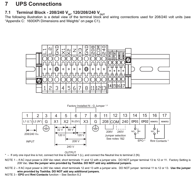
Terminal wiring and cable requirements
Terminal block type:
Type 1: Input at 208/240V, output at 120/208/240V, to be tripped according to the input voltage (208V short circuited to terminals 11-12, 240V short circuited to terminals 12-13)
Type 2: 240V input, 100/200V output, 100V output connected to 4-6 or 6-7 terminals, 200V output connected to 4-7 terminals
Cable specifications: All input, output, and grounding wires require 90 ℃ copper wire. The cable size and torque are shown in the following table:
Project Terminal Number Cable Size (AWG) -3.6kVA Cable Size (AWG) -5.2-6kVA Cable Size (AWG) -8kVA Cable Size (AWG) -10kVA Cable Size (AWG) -14-18kVA Cable Size (AWG) -22kVA Tightening Torque (lb. - in./N · m)
AC input line 1、2 10(8) 8(8) 8(1/0) 6(1/0) 4(1/0) 1(1/0) 14.2(1.56)
AC output line 4、5、7 12(8) 10(8) 8(1/0) 6(1/0) 4(1/0) 1(1/0) 14.2(1.56)
AC output neutral line 6 12(8) 10(8) 8(1/0) 6(1/0) 4(1/0) 1(1/0) 14.2(1.56)
ground wire 3、8 12(8) 10(8) 8(1/0) 6(1/0) 4(1/0) 1(1/0) 14.2(1.56)
EPO switch 14, 15 16 16 16 16 16 16 9.0 (0.99)
Remote switch 16, 17 16 16 16 16 16 16 9.0 (0.99)
Note: The maximum cable size that the terminal can accommodate is indicated in parentheses
Operation process and operating mode
Initial Startup (First Power Up)
Login: Log in with ADMIN privileges (default password ADMIN)
Parameter settings:
Enter the rated voltage (208V/230V/240V) and confirm with Write
Output rated voltage (208V/230V/240V), confirm with Write
Set date (format: Day mm/dd/yyyy, such as Mon 10/05/2009)
Set time (in 12 hour format, such as 12:15 PM)
Charging: After initial startup, the battery needs to be charged for at least 24 hours (with the input circuit breaker open), otherwise the backup time will be shortened
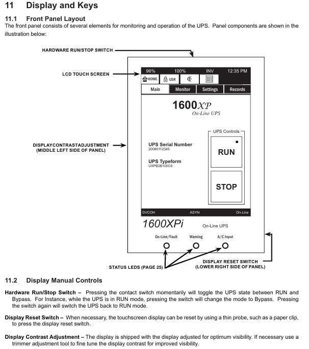
Normal start and stop
Start: Open the rear main circuit breaker (MCCB) of the UPS and confirm that the "On Line" green light on the front panel is on; If it's not on, press the RUN button for 3 seconds (hear a beep sound)
Stop: Press the STOP button for 3 seconds (after a beep, the "On Line" light goes out and enters bypass mode); To completely stop, turn off the MCCB circuit breaker (all sensitive loads must be turned off first)
Core operating mode
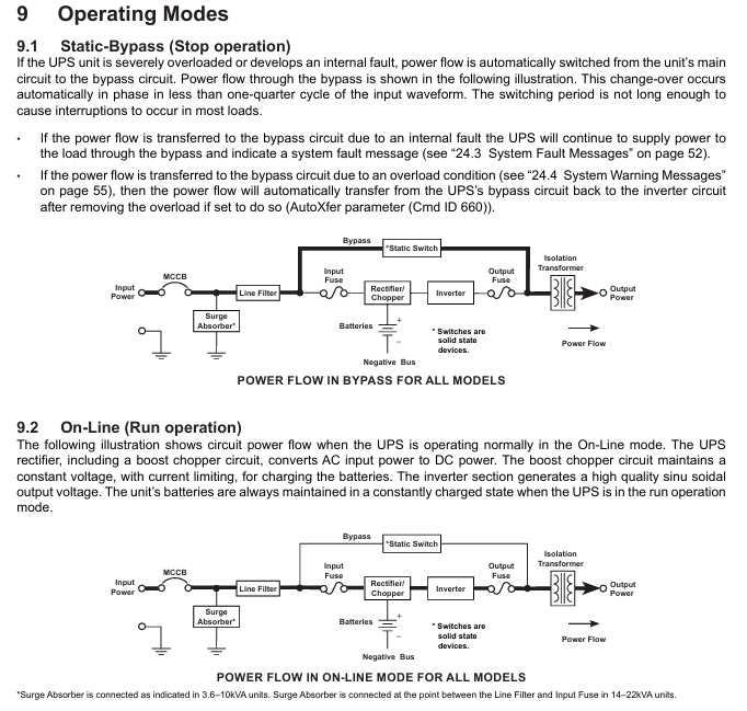
Static Bypass mode: Automatically switches when UPS overload or internal failure occurs, with power directly supplied to the load through the bypass from the input, with a switching time of less than 1/4 cycle (no load interruption); After overload relief, it can automatically switch back (AutoXfer parameter needs to be enabled)
On Line mode: Normal operation mode, the input AC is converted to DC through a rectifier (including a boost chopper circuit), and the charging battery is simultaneously supplied to the inverter to generate high-quality sine wave AC output. The battery is always in a charging state
Battery Backup Mode: When the mains power is interrupted, the battery immediately supplies DC to the inverter and converts it to AC output; Backup time is 5-8 minutes (full load, depending on model), and the power supply will automatically stop when the battery voltage drops to the "shutdown voltage (Vmin)"
EPO mode (Emergency Power Off): remotely close the EPO switch (normally open), immediately cut off the UPS input circuit breaker, output, and battery circuit; After activation, wait for 5 minutes for discharge before maintenance
Battery management and maintenance
Key parameters of battery
Nominal voltage (Vnom): 3.6KVA is 144Vdc, 5.2-6KVA is 216Vdc, 8-22KVA is 288Vdc
Low voltage alarm (Vlow): 3.6KVA is 130Vdc, 5.2-6KVA is 192Vdc, 8-22KVA is 246Vdc
Shutdown voltage (Vmin): 3.6KVA is 114Vdc, 5.2-6KVA is 170Vdc, 8-22KVA is 227Vdc
Charging parameters: Charging is divided into three stages (constant current 1A → constant voltage → float charging), and it takes 24 hours to fully charge (12 hours for 90% charging)
Battery testing and storage
Test:
Automatic testing: Enable at startup, wait for the 'Battery Test Frequency (CMD 655)' time before re enabling after completion
Manual testing: In UPS online mode, log in with ADMIN privileges, set CMD 652=Disable, CMD 653=Enable, and CMD 655=0, and press the "BattTest" button on CMD 609; Test failed with 'BTSTFL' warning displayed
Storage:
Before storage: Start up and run without load for 24 hours to fully charge the battery, stop UPS and turn off MCCB
Storage conditions: Original packaging, wooden/metal tray, temperature -20-40 ℃, avoid humidity/dust/vibration
Maintenance: Charge every 9 months for temperatures below 20 ℃, every 6 months for temperatures between 20-30 ℃, and every 3 months for temperatures between 30-40 ℃
Preventive maintenance and component replacement
Daily maintenance: Keep the ventilation openings clean and regularly remove dust (using a vacuum cleaner for dusty environments)
Component replacement cycle:
Aluminum electrolytic capacitor: every 7 years
Fuse: Every 7 years
Cooling fan: Every 3.5 years for environments between 30-40 ℃, and every 5 years for environments below 30 ℃ (non hot swappable, needs to be replaced after disconnecting and discharging)
Battery: Depending on the ambient temperature, 20-25 ℃ is 5 years, 30 ℃ is 3.5 years, 35 ℃ is 2.5 years, 40 ℃ is 1.8 years, and 45 ℃ is 1.25 years (requiring overall replacement, using the same model of battery pack)
Fault Handling and Technical Appendix
Fault and warning codes
Fault code (partially critical):
BYPOH: Bypass overheating, check the fan/ambient temperature (>40 ℃ needs to be cooled down), if the issue is not resolved within 1 hour, the bypass will stop
CHRGOV: Charger overvoltage, UPS failure, record operating conditions and contact Toshiba service
DCOV: DC bus overvoltage, check input wiring/load (such as motor load), restart ineffective, contact service
Warning code (partially critical):
AOH: If the environment is overheated (internal temperature>50 ℃), check the air conditioning/fan. If it is overheated, turn off the device
BLFE: End of battery life (5-year cycle), contact Toshiba for replacement
LB: Low battery (<90% capacity), immediately turn off the load in an orderly manner and press the STOP button
Technical specifications (core parameters)
Input: Voltage 208/240V ± 10% to -30%, frequency 45-65Hz (automatic detection), power factor 0.98 (typical), THD<5% (linear load)
Output: Voltage regulation ± 3%, THD<3% (linear load)/<6% (nonlinear load), overload capacity 125%/30 seconds, 150%/10 seconds, bypass overload 125%/10 minutes, 1000%/1 cycle
Efficiency: AC-DC-AC efficiency ≥ 83% (3.6-10KVA),>86% (14-22KVA)
Size and communication interface
Size and weight (example):
Model size (H × W × D, in./mm) Unit weight (lb./kg) Shipping weight (lb./kg)
3.6KVA 22.1×10×34 / 561×254×864 260 / 118 308 / 140
22KVA 39.0×17.5×36.1 / 991×445×917 866 / 393 928 / 421
Communication interface:
Standard: Remote Contacts (DB9 male), RS-232C (DB9 female), RemotEye 4 network card (supports SNMP/HTTP)
Optional: EMD environmental monitoring equipment (monitoring temperature, humidity, dry contact signals)
- YOKOGAWA
- Reliance
- ADVANCED
- SEW
- ProSoft
- WATLOW
- Kongsberg
- FANUC
- VSD
- DCS
- PLC
- man-machine
- Covid-19
- Energy and Gender
- Energy Access
- Renewable Integration
- Energy Subsidies
- Energy and Water
- Net zero emission
- Energy Security
- Critical Minerals
- A-B
- petroleum
- Mine scale
- Sewage treatment
- cement
- architecture
- Industrial information
- New energy
- Automobile market
- electricity
- Construction site
- HIMA
- ABB
- Rockwell
- Schneider Modicon
- Siemens
- xYCOM
- Yaskawa
- Woodward
- BOSCH Rexroth
- MOOG
- General Electric
- American NI
- Rolls-Royce
- CTI
- Honeywell
- EMERSON
- MAN
- GE
- TRICONEX
- Control Wave
- ALSTOM
- AMAT
- STUDER
- KONGSBERG
- MOTOROLA
- DANAHER MOTION
- Bentley
- Galil
- EATON
- MOLEX
- Triconex
- DEIF
- B&W
- ZYGO
- Aerotech
- DANFOSS
- KOLLMORGEN
- Beijer
- Endress+Hauser
- schneider
- Foxboro
- KB
- REXROTH
- YAMAHA
- Johnson
- Westinghouse
- WAGO
- TOSHIBA
- TEKTRONIX
- BENDER
- BMCM
- SMC
- HITACHI
- HIRSCHMANN
- XP POWER
- Baldor
- Meggitt
- SHINKAWA
- Other Brands
- UniOP
- KUKA
- IBA
- Beckhoff
-
ADLINK CPCI-6860A - 51-31310-OB10 industrial motherboard CompactPCI SBC
-
ADLINK AmITX-SL-G-H110 - 51-7A104-0A30 Mini-ITX Industrial Motherboard
-
ADLINK PXI-2005-003 - CPCI Industrial PC Data Acquisition Card Multi-Function DAQ
-
ADLINK DININ-814M - 51-14032-0A3D SCSI-100P cable connection Interface Terminal Board
-
ADLINK CPCI-3920NA/C2D15/M1G - 3U CompactPCI Intel Core 2 Duo Single Board Computer
-
ADLINK PCIE-8560 - 51-18014-0A20 Communication Card High Speed DAQ
-
ADLINK PCI-C154+ - Motion Control Card 4-axis Motion Controller Board
-
ADLINK PCI-RTV24 - image capture card Analog Video Frame Grabber
-
ADLINK NuPRO-842LV/P - 51-41360-0B30 Industrial Motherboard CPU Board
-
ADLINK cBP-3208/3208R - CPCI Board 3U 8-Slot CompactPCI Backplane
-
ADLINK PCI-8164 - 4-Axis Motion Controller PCI Card 51-12406-0A40
-
ADLINK PCIe-GIE64+ - 4-CH GigE Vision PoE+ Frame Grabber Video Capture Card
-
ADLINK CPCI-6860 / 6860A - CompactPCI Dual Xeon Single Board Computer
-
ADLINK IEC-915GV - REV 1.1 Industrial motherboard CPU Board
-
ADLINK ND-6520 - Technology RS-232 to RS-422RS-485 Converter NuDAM Module
-
ADLINK RTV-24 / PCI-MP4S - 51-12519-1C30 4-Channel Real Time Video Capture Board
-
ADLINK cPCI-6910 / cPCI-6910AM/M1G - cPCI-6910AM/DXL16/M1G/S80G(G)-3120 BOARD CompactPCI SBC
-
ADLINK NUPRO-A40H - Linghua 51-41807-1A30 Industrial Control Computer Motherboard
-
ADLINK USB-3488A - USB to GPIB INTERFACE USB-3488A(G) Controller Module
-
ADLINK PCI-8134A - motion control card 4-Axis Controller Card
-
ADLINK PCI-7432 - Board 32-Channel input / 32-output Isolated Digital I/O PCI Card
-
ADLINK PCI-8134A - 51-12421-0A10 motion controller card tested
-
ADLINK LPCIe-7230 - 32 CH Isolated Input/output Card 2 Interrupts Low Profile PCIe
-
ADLINK NuPRO-E340 - industrial computer motherboard 51-47807-0A30 PICMG 1.3 SHB
-
ADLINK PCI-7434 - High-speed Digital Acquisition Card 64-CH Isolated DO Card
-
ADLINK NuPRO-E330 - 51-41805-0A20 Indsutrial Board SHB Single Board Computer
-
ADLINK PCI-7248 - OPTO-22 48 CHANNEL DIO DIGITAL TTL/DTL I/O 51-12006-0A40 GP
-
ADLINK PCI-8134 - Motion control card 4-Axis Controller Card
-
ADLINK AMP-208C - Movimiento Control Tarjeta 51-12420-1A20 W/Expansión & Breakout
-
ADLINK PCI-8164 - 51-12406-0A40 PCB Board 4-Axis Motion Controller Card
-
ADLINK DIN-68Y-SGII / DIN-68M-J3A - Terminal Board Connector Interface Block
-
ADLINK PCIe-7432 - Technology 51-18402-0A10 PCIe Card With High Input Range
-
ADLINK PCI-8144 / PCI-8144N - Motion control card 4-Axis Stepper Controller Card
-
ADLINK HSL-HUB3/REPEATER - HIGH SPEED LINK EXTENSION MODULES Distributed Hub Module
-
ADLINK ND-6017 - Data Logging + Acquisition 8CH A/D input Mod NuDAM Module
-
ADLINK LPCIe-7250 - data acquisition card Low Profile 8-CH Relay Output Card
-
ADLINK PCI-7432 - I/O card 64-CH Isolated Digital Input Output PCI Card
-
ADLINK IMB-M43H - industrial control computer motherboard Q87 Chip Micro-ATX
-
ADLINK MP-C154 - Motion control Card 4-Axis Motion Controller Board
-
ADLINK PCI-RTV24 - image capture card Video Frame Grabber Card
-
ADLINK PCI-7250 - 8-CH Relay Output & 8-CH Isolated DI Card
-
ADLINK PCI-6308V - 8-CH 12-Bit Isolated Analog Output PCI Card PCB-I-E-1148=6EX2
-
ADLINK PCI-7248 - capture card 48-CH Opto-22 Compatible DIO Card
-
ADLINK HSL-AI16A02-M-VV - Analog Input Output Distributed Module
-
ADLINK NuPRO-A301 - Rev:1.4 NUPRO-A301 PICMG Full-Size Single Board Computer
-
ADLINK PCI-6208V-GL - 8-CH Voltage Analog Output PCI Card
-
ADLINK PCI-8134A - 51-12421-0A10 4-Axis Motion Controller Card
-
ADLINK MNET-S23 - TECHNOLOGY MNET S23 - SERVO DRIVER CONTROL MODULE
-
ADLINK M-342 - ATX I3 I5 I7 Q67 Industrial Motherboard
-
ADLINK NUPRO-780 - Industrial Motherboard CPU Board PICMG SBC
-
ADLINK MP-C154 / MP-C152 - 4-Axis Motion Control Card Pulse-Train Controller
-
ADLINK NuPRO-935A/LV10B0 - Motherboard 51-41802-0A10 GP w/RAM Industrial Control Board
-
ADLINK MP-C154 - Motion control card 4-Axis Motion Controller Mainboard
-
ADLINK PCI-7250 - PCI Acquisition Card 8-CH Relay Output Isolated DI Card
-
ADLINK ACL-7124 - Technology Inc.24 DIO Card Digital Input Output Card
-
ADLINK PCI-8554 A2 - Timer/Counter Data Acquisition Card
-
ADLINK DIN-825-GP4 - Terminal Block Interface Board Breakout Module
-
ADLINK NuPR0-761 - REV:1.1 Industrial motherboard Full-Size PICMG SBC
-
ADLINK MXE-1401/M8G (G) - Matrix Fanless Embedded Computer Industrial PC
-
ADLINK HSL-DI16DO16-UD-NN - Digital 16 Channel I/O Mod Distributed I/O Module
-
ADLINK ND6520 - NUDAM INTELLIGENT DA&C MODULE RS232-RS-422/RS485 CONVERTOR
-
ADLINK NUPRO-761 - REV:1.1 Industrial Motherboard CPU Board
-
ADLINK AMP-208C - Motion Control Card 51-12420-1A20 DSP-based 8-axis
-
ADLINK NuPRO-A301REV 1.4 - with packaging industrial computer motherboard PICMG SBC
-
ADLINK PCM-9112+ - 51-12300-0A2 industrial motherboard Multi-Function DAQ PC/104 Module
-
ADLINK PCM-7250+ - 8-CH Relay Outputs & 8-CH Isolated DI Module PC/104
-
ADLINK PCI-RTV24 - Image capture card Analog Video Frame Grabber
-
ADLINK PCI-8134 - Motion Controller PCI Card 4-Axis Controller Board
-
ADLINK PCI-7432 - Isolated Digital I/O PCI Card
-
ADLINK PCI-8554 A2 - acquisition card Timer/Counter Card
-
ADLINK PCI-8132 - Rev.A2 2-Axis Servo & Stepper Motion Controller Card
-
ADLINK PCI-8132 - Data Acquisition card 2-Axis Motion Controller Card
-
ADLINK EBP-13E4 - 51-46703-0A30 Industrial Backplane Board Passive Backplane
-
ADLINK PCI-800L - Electronic Card Interface Controller Card
-
ADLINK PCIe-GIE72 - 51-18531-0A10 PCB Board GigE Vision Frame Grabber
-
ADLINK DAQ-2010(G)-OOBO - Simultaneous-Sampling Multi-Function DAQ Card
-
ADLINK PCI-9112 - REV.B1 Multifunction DAQ Card Data Acquisition Card
-
ADLINK PCI-7230 - 51-12003-DA60 32-CH Isolated Digital I/O Card
-
ADLINK PCI-7432 - Data Acquisition Card Isolated Digital I/O PCI Card
-
ADLINK ETX-AT-N270-18/LXE - 51-71111-0A20 ETX CPU Module Motherboard
-
ADLINK HSL-DI32-UD-N - DIGITAL INPUT 32 POINTS MODULE Distributed I/O
-
ADLINK AMP-204C - Motion Control card DSP-Based 4-Axis Advanced Controller
-
ADLINK MNET-4XMOG-0050 - Four-axis Motion Controller Distributed Motion Module
-
ADLINK AMP-204C - Motion control card DSP-Based 4-Axis Pulse-Train Controller
-
ADLINK PCI-7442 - Switch card 64-Channel Datalogging & Acquisition Card
-
ADLINK M-302 - Industrial control motherboard ATX PC Board
-
ADLINK NUPRO-852 / NUPRO-852LV - Industrial motherboard Single Board Computer
-
ADLINK PCI-8134 - REV.B1. 4-Axis Motion Controller Card
-
ADLINK PCI-GIE62 + - 51-18502-0A20 2-CH GigE Vision Frame Grabber PoE Card
-
ADLINK PCI-MPG24 - 51-12523-0B20 MPEG4 Card Video Compression Hardware
-
ADLINK HSL-TB32-M-DIN - 32-CH I/O TERMINAL W/ HSL-AI16AO2-M-VV MODULE
-
ADLINK PCI-M114-GL - PCB Ver 2.1 Motion Controller Axis Card
-
ADLINK IMB-M40H - SYM76996H61 motherboard Industrial Computer Mainboard
-
ADLINK NUPRO-A40H - 51-41807-1A20 industrial control motherboard H61 Chip
-
ADLINK PCI-M114-GL - Axis Card Data Acquisition Card PCB VER2.2 Motion Controller
-
ADLINK PCI-8134 - Motion Controller PCI Card 4-Axis Controller Board
-
ADLINK PCI-8102 - Motion control card 2-Axis Servo & Stepper Controller
-
ADLINK NuPRO-841REV:3.0 - motherboard Industrial Control PC Board
-
ADLINK HSL-TB32-U-DIN REV A1 - Breakout Terminal Board Field I/O Module
-
ADLINK AMP-204C - Motion Control card DSP-Based 4-Axis Pulse-Train Controller
-
ADLINK NUPRO-A40H - 51-41807-1A20 industrial control motherboard H61 PC Board
-
ADLINK PCI-6308A / PCI-6308V - 51-12202-0A50 Isolated Analog Output Card
-
ADLINK AMP-204C - DSP-Based 4-Axis Advanced Pulse-Train Motion Controller
-
ADLINK PCI-7434 - Technology 64-Channel Isolated Digital I/O PCI Cards
-
ADLINK CPCI-6840 / CPCI-6840V / PM16/M1G-12G0 - CompactPCI Single Board Computer CPU Module
-
ADLINK PCIE-GIE74 - Motherboard Video Capture Card 51-18531-0A10 Frame Grabber
-
ADLINK NuPRO-E330 - industrial computer equipment motherboard Control Mainboard
-
ADLINK AMP-208C / 51-12420-1A20 - Motion Control Card W/ Expansion & Breakout Board
-
ADLINK HPCI-14S12U - industrial computer baseboard Passive Backplane 14 Slots
-
ADLINK PCI-8164 - 4-Axis Motion Controller PCI Card W/ 1x Cable, 1x Breakout Box
-
ADLINK PCIe-RTV24 - 51-18016-0A20 Image Acquisition Video Capture Card
-
ADLINK M-342 - 5 PCI ATX Motherboard Industrial PC Mainboard
-
ADLINK PCI-FIW64 - 4/2 Channel IEEE1394B Image Capture Card FireWire Frame Grabber
-
ADLINK PCI-7432 - digital IO card 64-CH Isolated Digital Input Output Card
-
ADLINK 51-12001-0C20 - Circuit Board PCI-7200 Data Acquisition Controller Card
-
ADLINK PXI-3920 - PXI 3U cPCI Industrial Controller Embedded System CPU Board
-
ADLINK NuPRO-841REV:2.0 - motherboard Industrial Control PC Board
-
ADLINK NuPro-E330 - 51-41805-0A20 PCB Industrial Control Computer Motherboard
-
ADLINK PCI-RTV24 - Image capture card Analog Video Frame Grabber
-
ADLINK PCI-7442 - Switch card 64-Channel Datalogging & Acquisition Card
-
ADLINK HPX-13S4 - device baseboard Passive Backplane Riser Card
-
ADLINK PCI-9112 REV A.1 - Multi Function DA&C Board Data Acquisition Card
-
ADLINK PCI-7248 - 51-12006-0A40 Card Control 48-CH Digital I/O Module
-
ADLINK CPCI-6860 / 6860A - motherboard CompactPCI Dual Xeon Single Board Computer
-
ADLINK DPAC-3020-11(G) - Embedded PC Automation Controller Machine Control Board
-
ADLINK NuPRO-841 REV:1.0 - industrial control motherboard CPU Board
-
ADLINK MNET-4XMOG-0050 - Four-axis Motion Controller MNET Motion Control Card
-
ADLINK ETX-AT-N270-18/LXE - 51-71111-0A20 ETX CPU Module Motherboard

K-JIANG

Add: Jimei North Road, Jimei District, Xiamen, Fujian, China
Tell:+86-15305925923