
K-WANG


Allen Bradley 1746-NI8 SLC 500 Analog Input Module
Allen Bradley 1746-NI8 SLC 500 Analog Input Module
Core framework and scope of application of the document
The document follows the logical mainline of "technical principles → practical procedures → fault handling", consisting of 10 core chapters and 4 appendices, with a complete structure and emphasis on practicality. The applicable product is the 1746-NI8 analog input module, which is a single slot module for SLC 500 control systems. It supports 8 analog input channels and can be connected to voltage (such as ± 10V DC, 0-5V DC) or current (such as 4-20mA, 0-20mA) signals. It is suitable for signal acquisition of sensors, transmitters and other devices and is widely used in industrial process parameter monitoring scenarios such as temperature, pressure, flow rate, liquid level, etc.
Core chapter content sorting
(1) Product Overview: Functions and Core Features
Module positioning and hardware composition
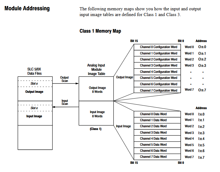
Core function: Convert analog input signals (voltage/current) into digital signals through an A/D converter, store them in an input mapping table, and provide them for SLC 500 processors (such as SLC 5/02, 5/03, 5/04) to read. It supports two interface modes: Class 1 (basic configuration) and Class 3 (extended configuration, including user-defined scaling and status monitoring).
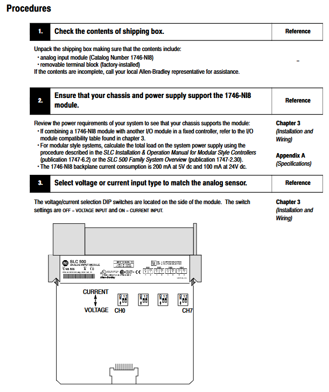
Hardware structure: including detachable terminal block (1746-RT25G), 8-channel status LED (green), 1-channel module status LED (green), voltage/current selection DIP switch, cable fixing slot, self-locking buckle, etc. The terminal block supports 18 position wiring and can be connected to shielded twisted pair cables (recommended Belden 8761).
Key technical characteristics
Channel configuration flexibility: 8 channels can be independently configured as single ended input or differential input, and differential input has stronger anti-interference ability; Supports 8 types of digital low-pass filtering frequencies (1Hz-75Hz), which can be selected according to the signal noise situation. Low frequency filtering (such as 1Hz) has good anti-interference effect, and high-frequency filtering (such as 75Hz) has fast response speed.
Self calibration and diagnosis: The module continuously self calibrates the enable channel without the need for manual calibration; Support power on diagnosis (internal circuit, memory detection) and channel diagnosis (open circuit, over range, configuration error detection), with fault status feedback through LED and status words.
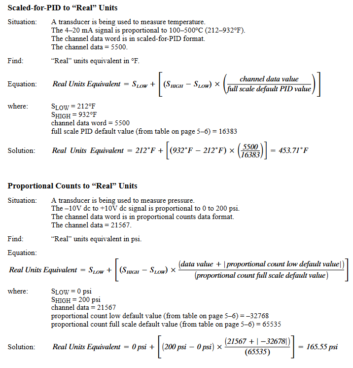
Data format diversity: The converted digital data supports 5 formats: engineering units (1mV/step voltage, 1 μ A/step current), PID scaling (0-16383 range, adapted to SLC PID algorithm), proportional counting (-32768-32767), 1746-NI4 compatible format, and user-defined range (Class 3 mode only).
(2) Installation and Wiring: Hardware Deployment Specification
Pre-installation preparation
Environmental requirements: Operating temperature of 0 ° C-55 ° C (not the rightmost slot), 0 ° C-60 ° C (rightmost slot, better heat dissipation), storage temperature of -40 ° C-85 ° C, relative humidity of 5% -95% (no condensation), suitable for industrial environment with pollution level 2, and installed in a closed metal enclosure (protection level reference NEMA 250 or EN/IEC 60529).
Static electricity protection: The module is sensitive to static electricity. When operating, it is necessary to wear a grounding wristband, touch a grounded object to discharge electricity, and do not touch the back panel pins. When idle, it should be stored in anti-static packaging.
Power requirements: Power is obtained through the SLC 500 chassis backplane, with+5V DC (200mA) for digital circuits and+24V DC (100mA) for analog circuits, without the need for external power supply; Calculate the total chassis load to avoid power overload (refer to SLC 500 system manual).
Module installation steps
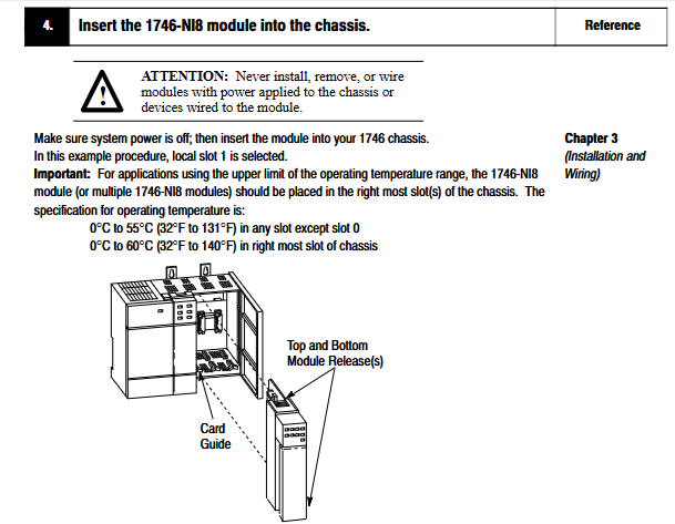
Slot selection: It can be installed in any slot of SLC 500 modular or extended chassis (except for processor slot 0). When installing multiple modules, it is recommended to place 1746-NI8 in the right slot (for better heat dissipation); The 2-plot expansion chassis (1746-A2) requires reference to the compatibility table, and some module combinations require an external power supply.
Physical installation: Align the module with the upper and lower rails of the chassis, slide it to the self-locking buckle, and ensure that the orange DIN rail locking screw is in a horizontal position (locked state); After installation, cover the unused slot (1746-N2 filler), and cover the exposed interconnection part of the last module with an end cap to prevent electric shock.
Terminal block operation: When disassembling, loosen the release screws on both sides and pull the handle upwards; When installing, first insert the handleless end (arc-shaped buckle) and rotate it to lock. The 1746-RTBS/RTB3S terminal needs to be locked/unlocked with a 3mm screwdriver (1492-N90) at a 73 ° angle.
Wiring specifications
Terminal definition: The terminal block contains 8 channels (each with ± end), 2 shielded terminals (channels 0-3 are connected to the upper shield, 4-7 are connected to the lower shield), and only one end of the shielding layer is grounded (to avoid ground circulation).
Wiring type:
Single ended input: Multiple channels share a common terminal, which can be connected to all "-" terminals through jumper wires, suitable for scenarios where signal sources and modules are grounded together.
Differential input: Each channel has independent ± terminals and strong resistance to common mode noise (common mode voltage range ± 10.5V), suitable for long-distance wiring or complex noise environments.
Wire requirements: Supports 0.25-2.5mm ² (22-14 AWG) solid/stranded copper wire (rated temperature ≥ 75 ° C), insulation layer thickness ≤ 1.2mm, terminal tightening torque ≤ 0.565N · m (5 lb in); The 2-wire/3-wire/4-wire transmitter needs to be matched with an external power supply (the module does not provide loop power).
(3) Run configuration: Address and channel management
Module identification and address allocation
ID code setting: The ID code for Class 1 mode is 3526 (8 input words+8 output words), and for Class 3 mode it is 12726 (16 input words+12 output words), which needs to be configured through programming software (such as RSLogix 500 V1.30+, APS). SLC 5/01 only supports Class 1 and 5/02 and above modes.
Memory Mapping:
Class 1: The output image (O: e.0-O: e.7) stores 8 channel configuration words, and the input image (I: e.0-I: e.7) stores 8 channel data words.
Class 3: The output image contains an additional 4 scaling range words (O: e.8-O: e.11), and the input image contains an additional 8 channel status words (I: e.8-I: e.15), which are used to monitor channel faults (such as open circuit, out of range).
Detailed explanation of channel configuration
Configuration word structure: 16 bit configuration word (O: e.x) defines channel parameters, and the key functions are as follows:
Bit 0-2: Input type (e.g. 101=4-20mA, 011=0-10V DC).
Bit 3-5: Data format (e.g. 000=engineering unit, 001=PID scaling).
Bit 6-7: Open circuit state (00=output 0, 01=upper limit value, 10=lower limit value, only valid for 4-20mA).
Bit 8-10: Filter frequency (100=10Hz, 011=20Hz).
Bit 11: Channel enabled (1=enabled, 0=disabled, data word cleared after disabled).
Configuration process: Define configuration parameters in an integer file (such as N10), write the configuration word to the module output image through the COPY instruction of the ladder program, and trigger configuration transfer with the "first scan bit (S: 1/15)" when powered on.
Data scaling and transformation
Engineering unit scaling: directly corresponding to physical quantities (such as 4-20mA corresponding to 100-500 ° C), data word value x scaling factor x (range/signal range)=actual value, for example: 5500 (1 μ A/step) x (932-212 ° F)/(20-4mA)=247.5 ° F.
PID scaling: 0-16383 corresponds to the full range of the signal, formula: actual value=lower limit value+(upper limit value - lower limit value) × (data word/16383).
User defined scaling (Class 3): Set upper and lower limits through O: e.8-O: e.11, actual value=data word x (range/(upper limit value - lower limit value)).
(4) Diagnosis and Troubleshooting: Problem Localization and Resolution
LED status interpretation
Channel status LED:
Always on: The channel is enabled and functioning normally.
Flashing: Channel malfunction (open circuit, over range, configuration error), needs to be judged in conjunction with the status word.
Off: Channel disabled or not configured.
Module status LED:
Always on: The module is running normally.
Extinguish: Module malfunction (power on diagnosis failure, hardware error), power off and restart required. If ineffective, contact the manufacturer.
Common faults and their solutions
Open circuit fault (4-20mA channel): Set the status word bit 12 to 1, check whether the sensor wiring is loose/broken, whether the sensor is damaged, and the module response time is 0.75-6ms (depending on the number of enabled channels).
Over/Under Range: Set the status words 13/14 to 1, check if the input signal exceeds the configured range (such as 4-20mA signal below 3.5mA or above 20.5mA), adjust the sensor or reconfigure the input type.
Configuration error: Set the status word bit 15 to 1. Check if the configuration word bits 0-7 (input type, data format, open circuit status) are an illegal combination (e.g. bits 6-7=11), and rewrite the configuration word.
Module unresponsive: Check the backplane power supply (+5V/+24V), whether the module is fully inserted into the slot, and whether the chassis is overloaded. If the fault persists after power failure and restart, the module needs to be replaced.
Maintenance and spare parts
Replaceable spare parts: terminal block (1746-RT25G), terminal cover (1746-R13), user manual (1746-6.8).
Maintenance taboos: Do not disassemble the module by yourself, and return it to the manufacturer for repair in case of malfunction; Only use dry anti-static cloth for cleaning, and do not use cleaning agents.
(5) Application example: Practical scenario reference
Basic Example: Current Value Display
Requirement: Collect single-phase motor current (4-20mA transmitter) and display the current value on an LED display (BCD format).
Configuration: Channel 0 is set to 4-20mA, engineering unit, 10Hz filtering, open circuit output 0; Scale 3500-20500 (data word range) to 0-100 (current range) using SCP command, convert TOD command to BCD and send it to the display.
Supplementary example: Multi parameter monitoring
Requirement: Monitor the three-phase motor current (L1-L3), tank pressure, and liquid level, switch the display through a selection switch, and trigger an alarm for low/high liquid level.
Configuration: Channel 0-2 (4-20mA, current), Channel 3 (4-20mA, pressure), Channel 4 (0-10V DC, liquid level); The ladder program includes scaling, BCD conversion, and alarm logic (trigger light for liquid level<12 inches or>110 inches).
Technical specifications and appendix supplements
Core specifications
Electrical parameters: A/D conversion to successive approximation type, common mode rejection ratio (CMRR) ≥ 75dB at DC and ≥ 100dB at 50/60Hz, channel update time 0.75m/s channel, total module update time 6ms (8-channel enabled).
Physical parameters: Size 56.6 × 12.1 × 77.5mm (2.23 × 0.48 × 3.05 inches), weight 30.9g (1.09 ounces), terminal supports 2 channels of 14 AWG wires.
Appendix Resources
Appendix A: Complete Electrical/Environmental/Physical Specification Table.
Appendix B: Channel Configuration Worksheet (including bit definition and setting examples).
Appendix C: ID code, address, and configuration word adaptation method for migrating from 1746-NI4 (4-channel) to 1746-NI8.
Appendix D: Binary Supplement Explanation (Explaining SLC Processor Data Storage Format).
Key precautions
Compatibility check: The compatibility of module combinations (refer to Table 3-2 in the manual) needs to be confirmed for the 2-slot expansion chassis (1746-A2), and some combinations require external power supply; The programming software needs to support Class 3 mode (such as RSLogix 500 V1.30+).
Anti interference measures: The distance between the analog line and the power line should be ≥ 15cm, shielded twisted pair cables should be used, and the shielding layer should be grounded at one end; Choose an appropriate filtering frequency (such as 10Hz filtering in a 60Hz environment) to reduce power frequency noise.
Safety regulations: Installation/disassembly/wiring must be powered off, hazardous environments (such as Class I Zone 2) must meet explosion-proof requirements, module grounding relies on DIN rails (recommended galvanized steel rails), fixed every 200mm.
- YOKOGAWA
- Reliance
- ADVANCED
- SEW
- ProSoft
- WATLOW
- Kongsberg
- FANUC
- VSD
- DCS
- PLC
- man-machine
- Covid-19
- Energy and Gender
- Energy Access
- Renewable Integration
- Energy Subsidies
- Energy and Water
- Net zero emission
- Energy Security
- Critical Minerals
- A-B
- petroleum
- Mine scale
- Sewage treatment
- cement
- architecture
- Industrial information
- New energy
- Automobile market
- electricity
- Construction site
- HIMA
- ABB
- Rockwell
- Schneider Modicon
- Siemens
- xYCOM
- Yaskawa
- Woodward
- BOSCH Rexroth
- MOOG
- General Electric
- American NI
- Rolls-Royce
- CTI
- Honeywell
- EMERSON
- MAN
- GE
- TRICONEX
- Control Wave
- ALSTOM
- AMAT
- STUDER
- KONGSBERG
- MOTOROLA
- DANAHER MOTION
- Bentley
- Galil
- EATON
- MOLEX
- Triconex
- DEIF
- B&W
- ZYGO
- Aerotech
- DANFOSS
- KOLLMORGEN
- Beijer
- Endress+Hauser
- schneider
- Foxboro
- KB
- REXROTH
- YAMAHA
- Johnson
- Westinghouse
- WAGO
- TOSHIBA
- TEKTRONIX
- BENDER
- BMCM
- SMC
- HITACHI
- HIRSCHMANN
- XP POWER
- Baldor
- Meggitt
- SHINKAWA
- Other Brands
- UniOP
- KUKA
- IBA
- Beckhoff
- ADLINK
-
Beckhoff EP9224-0037 - 4-Channel Power Distribution Box EtherCAT
-
Beckhoff CX2900-0026 - Solid State Flash Memory Card 20GB CFast
-
Beckhoff BK7500 - SERCOS Interface Fieldbus Bus Coupler Terminal
-
Beckhoff Ep2328-0002 - 4-Channel Input 4-Channel Output EtherCAT Box IP67
-
Beckhoff CX1020-0111 - Controller Kit Combo Interface Modules
-
B&R X20AI2237 - X20 System Analog Input Interface Module
-
Beckhoff CP2221-0010 - Multi-Touch Built-In Panel PC Touchscreen
-
Beckhoff CX1500-M310 - Fieldbus Master Interface Module 24V
-
Beckhoff CX2100-0904 - Power Charging Module Smart UPS Extension
-
Beckhoff CP3918-0000 - Multi-Touch Control Panel 18.5-Inch Monitor
-
Beckhoff CP2915-0000 - 15-Inch Multi-Touch Built-In Control Panel
-
Beckhoff CP7037-1027 - HMI Industrial Control Panel Built-In PC
-
Beckhoff EL3152 - 2-Channel Analog Input Terminal 4-20mA EtherCAT
-
Beckhoff CP6607-0000-0020 - 5.7-Inch Built-In Panel PC HMI Touch
-
Beckhoff EJ1809-0000 - 16-Channel Digital Input Pluggable Signal Level Terminal
-
Beckhoff AM8563-0N10-0000 - Synchronous Servo Motor
-
Beckhoff AX2006-S60600-520 - Compact Servo Drive Inverter
-
Beckhoff AM8053-0K20-0000 - Servo Motor with Planetary Gearbox AG3210
-
Beckhoff AM8042-0FH1-0000 - Synchronous Servo Motor
-
Rexroth R911338600 - IndraControl V HMI Terminal Beckhoff PCI Card FC9002
-
Beckhoff CP6500-1012-0060 - Control Cabinet PC Interface Unit
-
Beckhoff FC5202-0000 - 2-Channel DeviceNet Master PCI Interface Card
-
Beckhoff CP6606-0001-0020 - 7-Inch Economy Panel PC Touch
-
Beckhoff CP2921-0010 - Multi-Touch Integrated Control Panel Display
-
Beckhoff CP7802-0001-0010 - 15-Inch Touch Screen Control Panel HMI
-
Beckhoff C6920-0050 - Control Cabinet Industrial PC
-
Beckhoff BK9105 - EtherNet/IP Bus Coupler Network Interface
-
Beckhoff 31 Modules - Bus Terminal Slice I/O Lot Assortment
-
Beckhoff CX2020-0120 - Embedded PC Basic CPU Module 8GB CFast Card
-
Beckhoff CP7001-0000 - HMI Control Panel Touch Screen
-
B&R 7EX484.50-1 - System 2005 Controller Base Module Slots
-
Beckhoff EK1322 - 2-Port EtherCAT P Extension Feed-In Terminal
-
Beckhoff CP6606-0001-0020 - 7-Inch Single-Touch Economy Panel PC
-
Beckhoff CP6607-0001-0000 - Economy Installation Operator Panel PC 5.7-Inch
-
Beckhoff AX5103-0000-0200 - Digital Compact Servo Driver 3 Phase
-
Beckhoff CP7802-0001-0010 - 15-Inch Touch Screen Control Panel
-
Beckhoff AX8620 - Power Supply Module Axis System
-
Beckhoff CX2030-0121 - Embedded PC Controller Module
-
Beckhoff CP6606-0001-0020 - 7-Inch Economy Panel PC Touch Screen
-
Beckhoff CX2030-0121 - Embedded PC CPU Module Windows Standard 7
-
Beckhoff BX3100-0000 - PROFIBUS DP Bus Terminal Controller
-
Beckhoff CX1020-0000 - Controller Set with Power Supply Unit
-
Beckhoff EK1100 - EtherCAT Coupler Terminal Module Set
-
Beckhoff CP7002-1043-0010 - HMI Display Panel with Control Panel Bracket
-
Beckhoff AM8031-0D10-0000 - Synchronous Servo Motor
-
Beckhoff CX5130-0175 - Embedded PC 4GB RAM Controller
-
Beckhoff CX5130-0155 - Embedded PC Automation Controller
-
Beckhoff C6930-0010 - Control Cabinet Industrial PC Core Duo
-
Beckhoff CP3924-0000 - Multi-Touch Control Panel Display
-
Beckhoff AM8023-0F20-0000 - Synchronous Servo Motor
-
B&R KL3362 - Bus Terminal Thermocouple Input Module
-
Beckhoff AL2006-0000-0000 - Linear Servo Motor Three Phase
-
Beckhoff CX5140-0155 - Embedded PC CPU Controller Module
-
Beckhoff FC9002 - Ethernet PCI Network Interface Card
-
Beckhoff CP7203-0021-0040 - Built-In Panel PC 19-Inch Touch Screen
-
Beckhoff C6930-0020 - Control Cabinet Industrial PC HDD CF Card
-
Beckhoff CX2900-0033 - Memory Card CFast Storage
-
Beckhoff CP6201-0001-0020 - Built-In Panel PC Display
-
b+m surface systems C6930-1121-0060 - Industrial PC Beckhoff Core i7
-
Beckhoff CP2221-0010 - Multi-Touch Built-In Panel PC
-
Beckhoff C6017-0010 - Ultra-Compact Industrial PC
-
Beckhoff FC5102-0000 - 2-Channel CANopen PCI Interface Card
-
Beckhoff CP7021-0000-0000 - HMI Control Panel Interface
-
Beckhoff CP2216-0020 - Multi-Touch Built-In Panel PC
-
Beckhoff C6140 - Industrial PC Tower System Pentium 4
-
Beckhoff AM3033-1E40 - Servo Motor with Gearbox Assembly
-
Beckhoff CX9020-0115 - Embedded PC CPU Controller Module
-
Beckhoff CP6809-0001-0000 - Built-In Control Panel HMI Terminal
-
Beckhoff CP3919-0000 - Multi-Touch Control Panel Touchscreen Monitor
-
Beckhoff AM8053-0LHB-0000 - Synchronous Servo Motor
-
Beckhoff C6920-1028-0000 - Control Cabinet Industrial Computer PC
-
Beckhoff CX1100-0014 - Power Supply Unit for CX1030
-
Beckhoff CX9001-0101 - Embedded PC CPU Controller Module
-
Beckhoff CP3916-1428-0000 - Control Panel Multi-Touch Monitor
-
Beckhoff CP7037-1027-0010 - HMI Built-In Control Panel PC
-
Beckhoff CX1020-0120 - CPU Module DVI USB Windows Standard
-
Beckhoff CX5020-0121 - Embedded PC Controller Module
-
Beckhoff EL5042 - 2-Channel Encoder Interface BiSS C EtherCAT Terminal
-
Beckhoff CP7201-0021-0040 - Built-In Panel PC Touch Monitor
-
B&R X20-RT-8401 - reACTION Technology Module I/O Block
-
Beckhoff CP2915-0010 - HMI Control Panel Display Touch Screen
-
Beckhoff EL7221 - Servomotor Cyber Terminal EtherCAT Module
-
Beckhoff CX5140-0175 - Embedded PC CPU Module
-
Beckhoff C6017-0010 - Ultra-Compact Industrial PC
-
Beckhoff CX2020-0130 - Embedded PC Basic CPU Module
-
Beckhoff CX1030-0011 - Basic CPU Module Windows CE 6.0
-
Beckhoff AM8043-1E00-0000 - Synchronous Servo Motor
-
Beckhoff CX1020-0110 - CPU Module Controller Interface Bundle
-
Beckhoff C6930-1069-0030 - Control Cabinet Industrial PC Mainboard CB3054-0001
-
Beckhoff KL9528 - Power Supply Terminal Module
-
Beckhoff AM8053-0K20-0000 - Synchronous Servo Motor
-
Beckhoff CX5020-1111 - Embedded PC Controller Module
-
Beckhoff CX5130-0175 - Embedded PC CPU Module Intel Atom
-
Beckhoff CP6401-1024-0040 - Husky Display Control Panel HMI Terminal
-
Beckhoff CP2616-0000 - Multi-Touch Display Automation Panel PC
-
Beckhoff CP7921-1075-0000 - 12-Inch HMI Control Panel ELO Touch
-
Beckhoff C6930-0060 - Control Cabinet Industrial PC SSD
-
Beckhoff AX5112-0000 - Digital Compact Servo Drive 3 Phase
-
Beckhoff C6930-0040 - Control Cabinet Industrial PC Intel Core i5
-
Beckhoff CP2616-0000 - Multi-Touch Display Automation Panel PC
-
Beckhoff KL1414 - 4-Channel Digital Input Bus Terminal
-
Beckhoff CX1020-0000 - Basic CPU Module Controller
-
Beckhoff CP6201-1008-0000 - 12-Inch Built-In Panel PC
-
Beckhoff CP7021-0000 - HMI Control Panel Display Screen
-
Beckhoff AX5106-0000 - Digital Compact Servo Drive
-
Beckhoff BX3100-0000 - Profibus DP Bus Terminal Controller
-
Beckhoff CP2916-0000 - Multi-Touch Built-In Control Panel
-
Beckhoff C6925-0030 - Fanless Control Cabinet Industrial PC
-
Beckhoff C6330 - Industrial PC Motherboard Boser HS6237 Celeron
-
Beckhoff AM3033-0C00-0000 - Synchronous Servo Motor
-
Beckhoff EL6080 - EtherCAT Memory Terminal Module
-
Beckhoff CX2100-0014 - Power Supply Unit Module
-
Beckhoff CP6907-1000-000 - Economy Built-In Control Panel HMI
-
Bosch CP2715-1014-0010 - Panel PC Touch Screen Monitor
-
Beckhoff C6920-0050 - Control Cabinet Industrial PC
-
Beckhoff CP2712-1002-0000 - Baumann Automation Touch Control Panel PC
-
Beckhoff CX1001-0111 - Embedded PC CPU Power Supply Fieldbus Module Assembly
-
Beckhoff AM8061-0JH1-0000 - Synchronous Servo Motor
-
Nexcom EBS1575P - System Module Beckhoff Fieldbus Interface FC3101
-
Beckhoff CU8860-1000 - USB Extended Receiver Module
-
Beckhoff C9620-1080-0040 - Control Cabinet Industrial PC
-
Beckhoff C6640-0000 - Control Cabinet Industrial PC
-
Beckhoff C6525-0030 - Fanless Built-In Industrial PC
-
Beckhoff CX2030-0121 - Embedded PC CPU Module TwinCAT 2
-
Beckhoff CX5130-0155 - Embedded PC CPU Module
-
Beckhoff CX1020-0000 - Controller Set Module Combination Set
-
Beckhoff CU2005 - Industrial Ethernet Switch Module
-
Beckhoff ELM9410-0000 - Power Supply Terminal EtherCAT

K-JIANG

Add: Jimei North Road, Jimei District, Xiamen, Fujian, China
Tell:+86-15305925923