
K-WANG


Allen Bradley 1747-DCM Direct Communication Module
Allen Bradley 1747-DCM Direct Communication Module
Core framework and scope of application
The document follows the logical mainline of "safety specifications → system positioning → hardware configuration → installation and operation → fault handling", covering the entire process of module configuration from early stage to later stage maintenance. The applicable product is the 1747-DCM direct communication module, which serves as the communication interface module for SLC 500 series controllers (including extended chassis or modular controllers). It is connected to higher-level Allen Bradley controllers (such as PLC-2/3/5, SLC with RIO scanner) through RIO (Remote I/O) links to achieve data transmission between distributed processors, and is suitable for multi controller collaboration scenarios in industrial automation (such as multi area data exchange in production lines and remote device monitoring).
Core content sorting
(1) System positioning and hardware characteristics
Module core functions
Communication bridge function: manifested as an RIO adapter on the RIO link, it supports communication with PLC processors (such as PLC-5/250) or independent RIO scanners (1771-SN, 1747-SN) with integrated RIO scanners, enabling bidirectional data transmission between the upper level controller and the distributed SLC 500 controller.
Expansion node capability: Supports expansion node functionality. If all scanners and adapters on the RIO link have this capability, up to 32 adapters can be connected. At full baud rate, 82 Ω terminal resistors (1/2W) need to be connected at both ends of the link to ensure signal integrity.
Hardware structure and key components
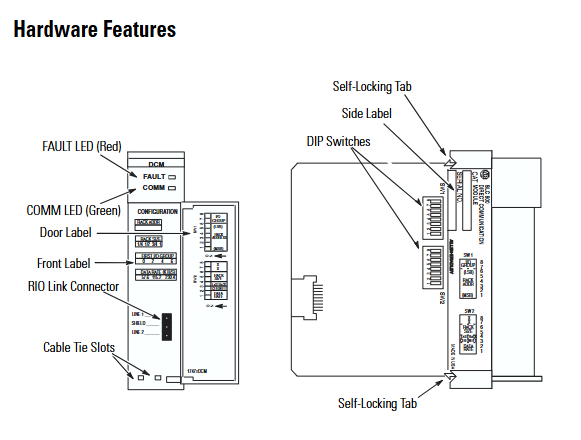
Physical components: including self-locking buckle (fixing module to chassis), 2 sets of DIP switches (configuration parameters), 2 status LEDs (red FAULT light, green COMM light), RIO link connector (front end), cable fixing slot, side label (module information), door label (parameter identification). The module is a full-size circuit board and needs to be installed in the non-zero slot of SLC 500 chassis (slot 0 reserved for CPU).
Status LED function:
FAULT light (red): Always on indicates an internal fault, flashing indicates a configuration error, and off indicates normal operation.
COMM light (green): Always on indicates normal communication, flashing indicates that the upper level processor is in programming/testing/fault mode, and off indicates communication interruption (such as scanner not connected or link failure).
(2) Module configuration: DIP switch parameter setting
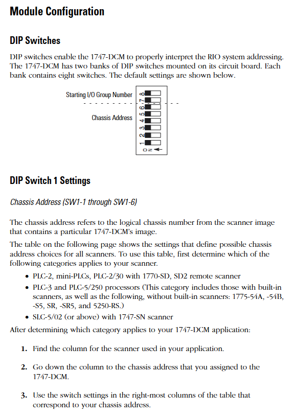
The 1747-DCM contains 2 sets of 8-bit DIP switches (SW1, SW2), which need to be configured before installation. The key parameters are as follows:
1. SW1 (chassis address and starting I/O group)
Rules for configuring switch position functions
SW1-1~SW1-6 logical chassis addresses correspond to the chassis number (octal) of the higher-level scanner. The switch status needs to be selected according to the scanner type (PLC-2/3/5, 1747-SN). For example, chassis address 1 of PLC-5/250 corresponds to SW1-1~5 being ON and SW1-6 being OFF
The starting I/O group numbers for SW1-7~SW1-8 only support even numbers (0/2/4/6) and need to match the chassis size:
-0 (ON+ON): Suitable for all sizes
-2 (ON+OFF): Suitable for 3/4, 1/2, and 1/4 sizes
-4 (OFF+ON): Suitable for 1/2 and 1/4 sizes
-6 (OFF+OFF): Only compatible with 1/4 size
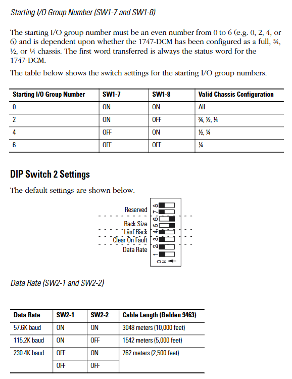
2. SW2 (data rate, fault handling, chassis attributes)
Rules for configuring switch position functions
SW2-1~SW2-2 data rates support three baud rates, which need to be consistent with the RIO link:
-57.6K baud (ON+ON): Maximum cable length 3048m (Belden 9463)
-115.2K baud (ON+OFF): Maximum 1524m
-230.4K baud (OFF+ON): maximum 762m
-Disable (OFF+OFF): Do not enable communication
When SW2-3 fault occurs, clear all data bits in the input image table (status bits are retained) - OFF: When there is a communication fault with RIO or when the upper level processor enters fault mode, clear all data bits in the input image table
-ON: Maintain the last state of the data bit in case of malfunction (confirm that there is no safety risk)
SW2-4 Last chassis identifier - OFF: The module shares logical chassis with other adapters and is the device with the highest I/O group number in the chassis
-ON: Not the last chassis device
SW2-5~SW2-6 logical chassis size allocation allocates the image space of modules in the scanner, determining the number of data transmission words:
-1/4 size (ON+ON): 1 status word+1 data word (2 words in total)
-1/2 size (ON+OFF): 1 status word+3 data words (4 words in total)
-3/4 size (OFF+ON): 1 status word+5 data words (a total of 6 words)
-Full size (OFF+OFF): 1 status word+7 data words (a total of 8 words)
Key note: Module images cannot cross logical chassis boundaries. For example, selecting the starting I/O group 6 while configuring as 1/2 size will trigger a configuration error.
(3) Installation and wiring: practical operation specifications
Pre-installation preparation
Power requirements: Power is obtained through the SLC 500 chassis backplane, requiring a current of+5V DC/360mA. Before installation, the remaining capacity of the chassis power supply needs to be confirmed; The fixed SLC 500 controller's 2-slot expansion chassis only supports one 1747-DCM and requires reference to the 1746-2.35 manual to confirm compatibility with other I/O modules.
Electrostatic protection: The module contains sensitive electronic components, and before installation/disassembly, it is necessary to touch a grounded object to discharge electricity and avoid electrostatic damage.
Switch pre configuration: DIP switch settings (chassis address, data rate, chassis size, etc.) must be completed before installing the module to avoid repeated disassembly after installation.
Module installation steps
Power off operation: Disconnect the chassis power supply to ensure safe installation.
Align the guide rail: Align the full-size circuit board with the upper and lower guide rails of the chassis, and confirm that the module is not installed in slot 0 (slot 0 is reserved for the CPU).
Fixed module: Slide the module to the self-locking buckle to ensure reliable contact between the module and the backplane connector.
Connect RIO cable: Connect the RIO link cable to the front-end connector of the module, use cable fixing slots and zip ties to secure the cable and prevent it from loosening.
Covering empty slots: Cover unused slots with 1746-N2 slot fillers to prevent dust from entering or electric shock risks.
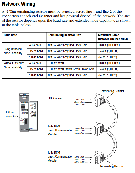
RIO Link Wiring Specification
Cable selection: It is recommended to use Belden 9463 cable, which supports differential signal transmission and has strong anti-interference ability.
Terminal resistance: A 1/2W terminal resistance should be connected at both ends of the link (scanner and the last physical device), and the resistance value should be selected based on whether the expansion node function is enabled
Enable extended node: Use 82 Ω for full baud rate (color ring: gray red black gold).
Extension node not enabled: 150 Ω (brown green brown gold) for 57.6K/115.2K baud, 82 Ω for 230.4K baud.
Wiring definition: The link includes Line 1 (blue), Line 2 (transparent), and a shielding layer. The shielding layer needs to be grounded at one end to avoid interference signals from ground current.
(4) Troubleshooting: LED Status and Handling
Fault interpretation of FAULT light (red)
|LED status | Reason for malfunction | Solution|
|Always on | Internal module faults (such as circuit and memory errors) | Restart I/O chassis containing 1747-DCM; If it still lights up after restarting, replace the module|
|Flashing | Configuration error (such as mismatch between I/O group and chassis size, chassis address error) | Check DIP switch settings to ensure compatibility between the starting I/O group and chassis size, and confirm that the chassis address matches the scanner|
|Extinguish | Normal state | No operation required|
COMM light (green) fault interpretation
|LED status | Reason for malfunction | Solution|
|Always on | Communication is normal | No operation required|
|Blinking | The upper level RIO scanner processor is in programming/testing/fault mode | Investigate the scanner processor fault and restart 1747-DCM after restoring normal mode|
|Extinguish | 1 The scanner is not connected to the processor
2. Scanner chassis disabled
3. No communication between 1747-DCM and scanner (baud rate mismatch, loose cable, connector not installed) | 1 Confirm that the scanner is correctly installed in chassis
2. Check the integrity of the scanner chassis and restart the module after repairing it
3. Verify the baud rate between 1747-DCM and scanner, check cable connections and connector installation|
(5) Technical specifications and safety standards
Core technical parameters
|Category | Specification|
|Power consumption | Backboard power supply,+5V DC/360mA|
|Working temperature | 0 ° C~+60 ° C (32 ° F~+140 ° F)|
|Storage temperature | -40 ° C~+85 ° C (-40 ° F~+185 ° F)|
|Humidity | 5%~95% (no condensation)|
|Certification | UL certification, CSA certification, Class I Division 2 (A/B/C/D groups) hazardous environment certification, CE compliance, C-Tick labeling|
|Physical dimensions | Full size SLC 500 module, compatible with standard SLC chassis slots|
Safety regulations for hazardous environments
The module is only applicable to Class I Division 2 (A/B/C/D groups) hazardous or non hazardous environments and is prohibited from being used in higher-level hazardous areas.
Taboos for operating in hazardous environments: Do not replace components or disconnect equipment (unless power is cut off), do not connect/disconnect components with electricity, all wiring must comply with NEC 501-4 (b) specifications, and do not replace components that may affect the applicability of hazardous environments.
Key considerations and supplementary resources
Compatibility check: The expansion of node functionality requires support from all devices (scanners, adapters) on the RIO link; When installing the 2-plot expansion chassis, it is necessary to confirm compatibility with other I/O modules (refer to manual 1746-2.35).
Configuration consistency: The DIP switch settings need to match the higher-level scanner, especially the chassis address, data rate, and chassis size, to avoid communication failures caused by parameter mismatches.
Wiring specifications: RIO cables should be kept away from power lines (to avoid electromagnetic interference), the shielding layer should be grounded at one end, terminal resistors should only be installed at both ends of the link, and intermediate equipment does not need to be installed.
- YOKOGAWA
- Reliance
- ADVANCED
- SEW
- ProSoft
- WATLOW
- Kongsberg
- FANUC
- VSD
- DCS
- PLC
- man-machine
- Covid-19
- Energy and Gender
- Energy Access
- Renewable Integration
- Energy Subsidies
- Energy and Water
- Net zero emission
- Energy Security
- Critical Minerals
- A-B
- petroleum
- Mine scale
- Sewage treatment
- cement
- architecture
- Industrial information
- New energy
- Automobile market
- electricity
- Construction site
- HIMA
- ABB
- Rockwell
- Schneider Modicon
- Siemens
- xYCOM
- Yaskawa
- Woodward
- BOSCH Rexroth
- MOOG
- General Electric
- American NI
- Rolls-Royce
- CTI
- Honeywell
- EMERSON
- MAN
- GE
- TRICONEX
- Control Wave
- ALSTOM
- AMAT
- STUDER
- KONGSBERG
- MOTOROLA
- DANAHER MOTION
- Bentley
- Galil
- EATON
- MOLEX
- Triconex
- DEIF
- B&W
- ZYGO
- Aerotech
- DANFOSS
- KOLLMORGEN
- Beijer
- Endress+Hauser
- schneider
- Foxboro
- KB
- REXROTH
- YAMAHA
- Johnson
- Westinghouse
- WAGO
- TOSHIBA
- TEKTRONIX
- BENDER
- BMCM
- SMC
- HITACHI
- HIRSCHMANN
- XP POWER
- Baldor
- Meggitt
- SHINKAWA
- Other Brands
- UniOP
- KUKA
- IBA
- Beckhoff
- ADLINK
-
Beckhoff CP6500-1012-0060 - Control Cabinet PC Interface Unit
-
Beckhoff FC5202-0000 - 2-Channel DeviceNet Master PCI Interface Card
-
Beckhoff CP6606-0001-0020 - 7-Inch Economy Panel PC Touch
-
Beckhoff CP2921-0010 - Multi-Touch Integrated Control Panel Display
-
Beckhoff CP7802-0001-0010 - 15-Inch Touch Screen Control Panel HMI
-
Beckhoff C6920-0050 - Control Cabinet Industrial PC
-
Beckhoff BK9105 - EtherNet/IP Bus Coupler Network Interface
-
Beckhoff 31 Modules - Bus Terminal Slice I/O Lot Assortment
-
Beckhoff CX2020-0120 - Embedded PC Basic CPU Module 8GB CFast Card
-
Beckhoff CP7001-0000 - HMI Control Panel Touch Screen
-
B&R 7EX484.50-1 - System 2005 Controller Base Module Slots
-
Beckhoff EK1322 - 2-Port EtherCAT P Extension Feed-In Terminal
-
Beckhoff CP6606-0001-0020 - 7-Inch Single-Touch Economy Panel PC
-
Beckhoff CP6607-0001-0000 - Economy Installation Operator Panel PC 5.7-Inch
-
Beckhoff AX5103-0000-0200 - Digital Compact Servo Driver 3 Phase
-
Beckhoff CP7802-0001-0010 - 15-Inch Touch Screen Control Panel
-
Beckhoff AX8620 - Power Supply Module Axis System
-
Beckhoff CX2030-0121 - Embedded PC Controller Module
-
Beckhoff CP6606-0001-0020 - 7-Inch Economy Panel PC Touch Screen
-
Beckhoff CX2030-0121 - Embedded PC CPU Module Windows Standard 7
-
Beckhoff BX3100-0000 - PROFIBUS DP Bus Terminal Controller
-
Beckhoff CX1020-0000 - Controller Set with Power Supply Unit
-
Beckhoff EK1100 - EtherCAT Coupler Terminal Module Set
-
Beckhoff CP7002-1043-0010 - HMI Display Panel with Control Panel Bracket
-
Beckhoff AM8031-0D10-0000 - Synchronous Servo Motor
-
Beckhoff CX5130-0175 - Embedded PC 4GB RAM Controller
-
Beckhoff CX5130-0155 - Embedded PC Automation Controller
-
Beckhoff C6930-0010 - Control Cabinet Industrial PC Core Duo
-
Beckhoff CP3924-0000 - Multi-Touch Control Panel Display
-
Beckhoff AM8023-0F20-0000 - Synchronous Servo Motor
-
B&R KL3362 - Bus Terminal Thermocouple Input Module
-
Beckhoff AL2006-0000-0000 - Linear Servo Motor Three Phase
-
Beckhoff CX5140-0155 - Embedded PC CPU Controller Module
-
Beckhoff FC9002 - Ethernet PCI Network Interface Card
-
Beckhoff CP7203-0021-0040 - Built-In Panel PC 19-Inch Touch Screen
-
Beckhoff C6930-0020 - Control Cabinet Industrial PC HDD CF Card
-
Beckhoff CX2900-0033 - Memory Card CFast Storage
-
Beckhoff CP6201-0001-0020 - Built-In Panel PC Display
-
b+m surface systems C6930-1121-0060 - Industrial PC Beckhoff Core i7
-
Beckhoff CP2221-0010 - Multi-Touch Built-In Panel PC
-
Beckhoff C6017-0010 - Ultra-Compact Industrial PC
-
Beckhoff FC5102-0000 - 2-Channel CANopen PCI Interface Card
-
Beckhoff CP7021-0000-0000 - HMI Control Panel Interface
-
Beckhoff CP2216-0020 - Multi-Touch Built-In Panel PC
-
Beckhoff C6140 - Industrial PC Tower System Pentium 4
-
Beckhoff AM3033-1E40 - Servo Motor with Gearbox Assembly
-
Beckhoff CX9020-0115 - Embedded PC CPU Controller Module
-
Beckhoff CP6809-0001-0000 - Built-In Control Panel HMI Terminal
-
Beckhoff CP3919-0000 - Multi-Touch Control Panel Touchscreen Monitor
-
Beckhoff AM8053-0LHB-0000 - Synchronous Servo Motor
-
Beckhoff C6920-1028-0000 - Control Cabinet Industrial Computer PC
-
Beckhoff CX1100-0014 - Power Supply Unit for CX1030
-
Beckhoff CX9001-0101 - Embedded PC CPU Controller Module
-
Beckhoff CP3916-1428-0000 - Control Panel Multi-Touch Monitor
-
Beckhoff CP7037-1027-0010 - HMI Built-In Control Panel PC
-
Beckhoff CX1020-0120 - CPU Module DVI USB Windows Standard
-
Beckhoff CX5020-0121 - Embedded PC Controller Module
-
Beckhoff EL5042 - 2-Channel Encoder Interface BiSS C EtherCAT Terminal
-
Beckhoff CP7201-0021-0040 - Built-In Panel PC Touch Monitor
-
B&R X20-RT-8401 - reACTION Technology Module I/O Block
-
Beckhoff CP2915-0010 - HMI Control Panel Display Touch Screen
-
Beckhoff EL7221 - Servomotor Cyber Terminal EtherCAT Module
-
Beckhoff CX5140-0175 - Embedded PC CPU Module
-
Beckhoff C6017-0010 - Ultra-Compact Industrial PC
-
Beckhoff CX2020-0130 - Embedded PC Basic CPU Module
-
Beckhoff CX1030-0011 - Basic CPU Module Windows CE 6.0
-
Beckhoff AM8043-1E00-0000 - Synchronous Servo Motor
-
Beckhoff CX1020-0110 - CPU Module Controller Interface Bundle
-
Beckhoff C6930-1069-0030 - Control Cabinet Industrial PC Mainboard CB3054-0001
-
Beckhoff KL9528 - Power Supply Terminal Module
-
Beckhoff AM8053-0K20-0000 - Synchronous Servo Motor
-
Beckhoff CX5020-1111 - Embedded PC Controller Module
-
Beckhoff CX5130-0175 - Embedded PC CPU Module Intel Atom
-
Beckhoff CP6401-1024-0040 - Husky Display Control Panel HMI Terminal
-
Beckhoff CP2616-0000 - Multi-Touch Display Automation Panel PC
-
Beckhoff CP7921-1075-0000 - 12-Inch HMI Control Panel ELO Touch
-
Beckhoff C6930-0060 - Control Cabinet Industrial PC SSD
-
Beckhoff AX5112-0000 - Digital Compact Servo Drive 3 Phase
-
Beckhoff C6930-0040 - Control Cabinet Industrial PC Intel Core i5
-
Beckhoff CP2616-0000 - Multi-Touch Display Automation Panel PC
-
Beckhoff KL1414 - 4-Channel Digital Input Bus Terminal
-
Beckhoff CX1020-0000 - Basic CPU Module Controller
-
Beckhoff CP6201-1008-0000 - 12-Inch Built-In Panel PC
-
Beckhoff CP7021-0000 - HMI Control Panel Display Screen
-
Beckhoff AX5106-0000 - Digital Compact Servo Drive
-
Beckhoff BX3100-0000 - Profibus DP Bus Terminal Controller
-
Beckhoff CP2916-0000 - Multi-Touch Built-In Control Panel
-
Beckhoff C6925-0030 - Fanless Control Cabinet Industrial PC
-
Beckhoff C6330 - Industrial PC Motherboard Boser HS6237 Celeron
-
Beckhoff AM3033-0C00-0000 - Synchronous Servo Motor
-
Beckhoff EL6080 - EtherCAT Memory Terminal Module
-
Beckhoff CX2100-0014 - Power Supply Unit Module
-
Beckhoff CP6907-1000-000 - Economy Built-In Control Panel HMI
-
Bosch CP2715-1014-0010 - Panel PC Touch Screen Monitor
-
Beckhoff C6920-0050 - Control Cabinet Industrial PC
-
Beckhoff CP2712-1002-0000 - Baumann Automation Touch Control Panel PC
-
Beckhoff CX1001-0111 - Embedded PC CPU Power Supply Fieldbus Module Assembly
-
Beckhoff AM8061-0JH1-0000 - Synchronous Servo Motor
-
Nexcom EBS1575P - System Module Beckhoff Fieldbus Interface FC3101
-
Beckhoff CU8860-1000 - USB Extended Receiver Module
-
Beckhoff C9620-1080-0040 - Control Cabinet Industrial PC
-
Beckhoff C6640-0000 - Control Cabinet Industrial PC
-
Beckhoff C6525-0030 - Fanless Built-In Industrial PC
-
Beckhoff CX2030-0121 - Embedded PC CPU Module TwinCAT 2
-
Beckhoff CX5130-0155 - Embedded PC CPU Module
-
Beckhoff CX1020-0000 - Controller Set Module Combination Set
-
Beckhoff CU2005 - Industrial Ethernet Switch Module
-
Beckhoff ELM9410-0000 - Power Supply Terminal EtherCAT
-
Beckhoff AM8023-0EH1-0000 - Synchronous Servo Motor
-
Beckhoff CX5020-0112 - Embedded PC CF Memory Card
-
Beckhoff CP3921-0010 - Control Panel Multi-Touch Screen
-
Beckhoff CP7232-1000-0000 - Industrial Panel PC Touch Screen
-
Beckhoff C6525-1022-0005 - Fanless Built-In Industrial PC
-
Beckhoff AM3052-0K41-1001 - Synchronous Servo Motor
-
Beckhoff CP2921-0010 - Multi-Touch Built-In Control Panel
-
Beckhoff c6017-0010 - Ultra-Compact Industrial PC
-
Beckhoff AX5106-0000-0200 - Servo Drive Intelligent Drive Module
-
Beckhoff BK7200 - Fipio Bus Coupler PLC Module
-
Beckhoff EP-M845B - Industrial Mainboard Motherboard Rev 2.1
-
Beckhoff CX5020-0111 - Embedded PC CPU Module
-
Beckhoff CP6802-0001-0010 - Built-In HMI Control Panel
-
Beckhoff CX2100-0004 - Power Supply Unit Module
-
Beckhoff C6320 - Control Cabinet Industrial PC
-
Beckhoff C6525-0030 - Fanless Built-In Industrial PC Celeron
-
Beckhoff CX1010-0112 - Embedded PC Controller Module
-
Beckhoff EPP6002-0002 - EtherCAT Box Serial Interface
-
Beckhoff CP7721-1084-0020 - Touch Panel PC Trumpf Laser Screen
-
Beckhoff C6140 - Industrial PC Mainboard Tower Computer

K-JIANG

Add: Jimei North Road, Jimei District, Xiamen, Fujian, China
Tell:+86-15305925923