
K-WANG


Tektronix MSO4000/DPO4000 series digital fluorescence oscilloscope
Tektronix MSO4000/DPO4000 series digital fluorescence oscilloscope
Document Overview
This manual is the official guidance document for the Tektronix MSO4000 (mixed signal) and DPO4000 (digital fluorescence) series oscilloscopes, covering 2-channel (such as MSO4032/DPO4032) and 4-channel (such as MSO4054/DPO4104) models, with a core focus on high-end electronic design and debugging (such as embedded systems, automotive electronics, communication equipment). The document structure includes 11 core chapters and 1 appendix, catering to the complex analysis needs of novice operators and professional engineers, highlighting the ability to synchronously collect and decode "analog+digital" mixed signals, as well as professional measurement functions extended through application modules.
Core parameters and characteristics of the product
1. Model classification and key parameters
Series models, analog channels, digital channels, bandwidth, maximum sampling rate, record length, typical applications
MSO4000 MSO4032 2 2 16 350MHz 2GS/s 10M point mixed signal debugging (such as I2C/SPI)
MSO4000 MSO4054 4 4 16 500MHz 2GS/s 10M point multi-channel timing analysis
MSO4000 MSO4104 4 4 16 1GHz 5GS/s 10M high-speed signal capture (such as USB 2.0)
DPO4000 DPO4034 4-350MHz 2GS/s 10M point analog signal waveform analysis
DPO4000 DPO4104 4-1GHz 5GS/s 10M point high bandwidth signal (such as RF) testing
2. Core Features
Mixed signal analysis (MSO series exclusive): 16 digital channels and analog channels are synchronously collected, supporting MagniVu mode (60.6ps timing resolution), which can capture narrow pulses and edge jitter of digital signals;
High speed signal processing: The highest sampling rate for all channels is 5GS/s, with a recording length of 10M points. It supports a refresh rate of 50000 waveforms per second and can quickly capture transient anomalies;
Flexible triggering and decoding: 8 types of triggering types cover edge, pulse width, logic mode, and bus (such as I2C/CAN/RS-232), supporting sequence triggering (A event+delayed B event);
Professional Expansion Module: Extend functionality through modules such as DPO4PWR (Power Quality/Switching Loss Measurement) and DPO4USB (USB 2.0 Decoding) to meet vertical domain requirements;
Convenient data management: Supports CompactFlash, USB storage, Ethernet remote control (e * Scope), USBTMC protocol for direct connection to PC.
Safety operation standards
1. Electrical safety
Input voltage limit:
1M Ω input: maximum 400Vpk (DF ≤ 39.2%), 250V RMS (below 130kHz), 20dB/decade attenuation above 130kHz;
50 Ω input: maximum 5V (peak to peak value ≤± 20V), automatically switches to 1M Ω protection when overvoltage occurs;
Probe safety:
P6139A passive probe: CAT II 300V RMS, CAT III 150V RMS, with 20dB/decade attenuation for frequencies above 2.5MHz;
Logic probe P6516: maximum input ± 15V, threshold accuracy ± (100mV+3% threshold);
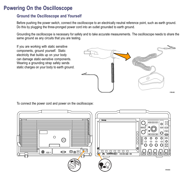
Grounding requirements: A 3-pin power cord must be used, and the equipment chassis must be reliably grounded. Floating operation is prohibited; During measurement, the reference end of the probe should only be connected to the signal ground and should not be connected to the mains ground.
2. Operation taboos
Do not use in damp (>90% RH) or explosive environments, and avoid liquid contact with equipment;
Before connecting/disconnecting the probe, the signal source must be disconnected first, and live plugging and unplugging are prohibited;
Before disassembling the application module or CF card, it is necessary to shut down and avoid short circuiting the battery or probe contacts.
Basic operation process
1. Probe operation and calibration
Key requirements for operation type steps
Passive probe compensation (P6139A) 1. Probe connected to CH1, set to 10X; 2. Connected to PROBE COMP( 2.5V@1kHz ); 3. Autoset; 4. Adjust the compensation hole to a flat square wave without overshoot/depression, and re compensate every time the channel is changed
Signal Path Compensation (SPC): 1. Disconnect all probes and preheat for 20 minutes; 2. Press 【 Utility 】 → 【 Calibration 】 → 【 Signal Path 】; 3. Wait for 10 minutes and display "Pass". If the environmental temperature difference exceeds 10 ℃ or once a week, ensure low range (≤ 5mV/div) measurement accuracy
Firmware Upgrade 1. Download firmware. img from the official website to the USB root directory; 2. Turn off the oscilloscope and plug it into a USB port, and it will automatically upgrade when turned on; 3. After upgrading, verify the version (Utility ->Config ->About). During the upgrade, it is forbidden to power off or unplug the USB. It is recommended to use a blank USB to avoid file conflicts
2. Channel settings
Simulation channel:
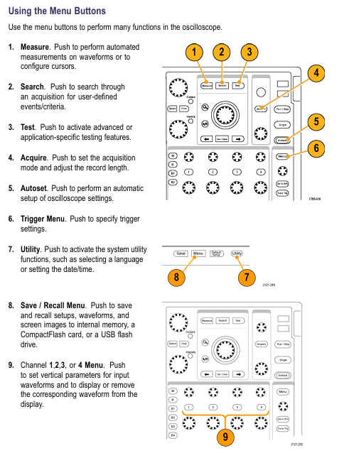
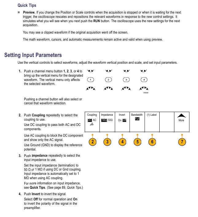
Press the CH1-CH4 button to activate the channel, press 【 Coupling 】 to select DC/AC/GND (AC coupling blocks DC, GND displays reference ground);
Select 1M Ω/50 Ω (50 Ω only DC/GND coupling, maximum 1V/div) according to the 'Impedance' button;
Select Full/250MHz/20MHz (20MHz is used to filter out high-frequency noise) according to [Bandwidth];
Digital Channel (MSO Series):
Press 【 D15-D0 】 to activate the digital channel, and press 【 On/Off 】 to select D7-D0/D15-D8;
Set the threshold according to [Thresholds] (such as TTL 1.4V, 3.3V CMOS 1.65V);
Press MagniVu → On to enable 60.6ps timing resolution (for precise measurement of digital edges).
Core functional system
1. Collection system (5 modes)
The working principle of the collection mode is applicable to different scenarios
Sample: equidistant sampling, 1 point/interval regular stable signal (sine wave/square wave), strong real-time performance
Peak Detect records the maximum/minimum value of each interval to capture narrow spikes (≥ 1ns), effective at low-speed time base (≥ 5 μ s/div)
Hi Res (High Resolution) calculates the average value of each interval sample to reduce noise and improve the resolution of low-frequency signals
Envelope records the maximum/minimum waveform collected multiple times, observing the range of signal amplitude changes (such as power ripple fluctuations)
Average: After multiple acquisitions, the average (4/16/64/128 optional) suppresses random noise, and averaging 128 times can significantly improve the signal-to-noise ratio
2. Trigger system (8 types)
Trigger type key parameters applicable scenarios
Edge slope (rising/falling), coupling (DC/LF Reject/HF Reject), stable display of conventional signals (such as clock, square wave)
Pulse Width condition (>/</=/≠), width (33ns-10s), polarity capture of abnormal pulses (such as narrow pulse interference in communication links)
Logic channel status (High/Low/Don't Care), clock edge multi-channel logic combination triggering (such as I2C SDA=1 and SCL=0)
Setup&Hold: Clock channel, data channel, violation time detection bus timing violation (such as insufficient setup time between FPGA and memory)
Bus type (I2C/CAN/RS-32, etc.), trigger conditions (address/data/error), decode and trigger bus specific events (such as Write operation for I2C address 0x7F)
3. Measurement and analysis functions
Automatic measurement: Supports 11 types of parameters, with a maximum of 8 displayed simultaneously. The key measurements are as follows:
Measurement type definition accuracy conditions
The amplitude of the reciprocal signal of the first cycle of frequency (Freq) is ≥ 1div, without any truncation
Rise Time: The time signal with an amplitude of 10% -90% has no noise on the rising edge and is horizontally scale adapted (such as 10ns/div)
Peak to peak value (Pk Pk) full waveform maximum minimum value waveform without truncation, vertical scale adaptation (such as 100mV/div)
FFT spectrum analysis:
Press 【 Math 】 → 【 FFT 】, select the source channel (such as CH1);
Press [Window] to select the window function (Rectangular: optimal frequency resolution; Blackman Harris: excellent amplitude accuracy);
Select dBV RMS/Linear RMS according to 'Vertical Units' (dBV RMS is suitable for multi frequency comparison);
Histogram analysis:
Press 【 Measure 】 → 【 Waveform Histograms 】, select Vertical (voltage)/Horizontal (time);
Set the boundary of the rectangular frame (Horizon. Limits/Vert. Limits) and add statistical measurements (such as σ 1/σ 2/σ 3);
Vertical histograms are used to measure noise (the smaller the σ value, the lower the noise), while horizontal histograms are used to measure jitter.
Data Management and Communication
1. Storage medium operation
Storage content operation steps, file name format, 1MB capacity, approximate storage quantity
Waveform file 1. Press 【 Save/Recall 】 → 【 Save Waveform 】; 2. Select [To File] → [Internal File Format (. ISF)]; 3. Edit file name tekXXXX_Cx.ISF (x=1-4) 18 (10M point waveform)
Set file 1. Press 【 Save/Recall 】 → 【 Save Setup 】; 2. Select [To File] or [To Setup 1-10]; 3. Confirm to save 250 units of tekXXXXX.SET
Screen Image 1. Press 【 Save/Recall 】 → 【 Save Screen Image 】; 2. Select format (. BMP/. TIF/. PNG); 3. Press [OK Save] tekXXXXX.BMP 16
2. Remote communication settings
Ethernet(e*Scope):
Connect the Ethernet cable to the rear panel LAN port, press 【 Utility 】 → 【 I/O 】 → 【 Ethernet Network Settings 】;
Set DHCP to On (automatically obtain IP) or Off (manually set IP);
Input the oscilloscope IP into the PC browser and access the e * Scope interface to control the oscilloscope;
USBTMC (PC Control):
Connect the Rear panel USB Device port of the oscilloscope to the PC using a USB cable;
Install VISA driver (official website download), and send SCPI command through LabVIEW/Excel on the PC end;
Application modules and case studies
1. Optional application modules
Module model, function, applicable scenarios
DPO4PWR power analysis: power quality, switching losses, harmonics, safe working area (SOA) power supply design (such as AC-DC converter efficiency testing)
DPO4USB 2.0 decoding: low-speed/full speed bus triggering and decoding, supporting PID error detection and USB device debugging (such as troubleshooting USB disk enumeration failures)
DPO4AUTO Automotive Bus: CAN/LIN triggering and decoding, supporting frame type/ID filtering for automotive electronics (such as CAN bus communication faults)
DPO4VID video trigger: HDTV (such as 1080i), custom video (3-4000 lines), video equipment (such as monitoring camera signal testing)
2. Typical troubleshooting cases
Case 1: Abnormal RS-232 bus
Connection: CH1 is connected to the TX line, CH2 is connected to the RX line, press 【 B1 】 → 【 Bus 】 → 【 RS-232 】;
Set parameters: baud rate 9600, data bit 8, parity None, stop bit 1;
Trigger: Press 【 Trigger Menu 】→【 Type 】→【 Bus 】→【 Trigger On 】→【 Tx Data 】, set the trigger data to 0x55;
Analysis: Press 【 Search 】 → 【 Bus 】 → 【 Tx Data 】, mark all 0x55 frames, and use Wave Inspector to view the timing of abnormal frames;
Case 2: Relay arc capture
Parameter setting: CH1 is connected to both ends of the relay, Vertical scale 100V/div,Horizontal scale 10μs/div;
Trigger: Press 【 Trigger Menu 】→【 Type 】→【 Edge 】→【 Slope 】→【 Rising 】, set the trigger level to 50V;
Capture: Press [Single] to trigger when the relay is disconnected, observe the peak generated by the arc (amplitude>200V);
Optimization: Zoom in on the peak area (Zoom x 10) and measure the peak width with the cursor (approximately 50ns).
Appendix and Support
1. Key performance parameters
System parameter description
Analog channel DC gain accuracy ± 1.5% (1M Ω path), ± 3% (50 Ω path), with a 0.1% decrease per ℃ above 30 ℃
The timing resolution of the digital channel (MSO) is typically 121ps, while in MagniVu mode it is 60.6ps
Trigger system edge trigger sensitivity DC coupling: 1div (DC-10MHz), 2div (100-1GHz)
Display system screen resolution 1024 × 768 pixels (10.4-inch XGA)
2. Probe compatibility
Probe model, type, bandwidth, maximum voltage, applicable scenarios
P6139A (standard) passive voltage 500MHz CAT II 300V RMS conventional analog signal measurement
P6516 (MSO standard) logic probe DC-100MHz ± 15V digital channel signal acquisition
TCP303 (optional) current probe DC-15MHz 150A RMS high current AC/DC measurement
P5200 (optional) differential probe DC-200MHz 1000V RMS high-voltage differential signal (such as motor drive)
- YOKOGAWA
- Reliance
- ADVANCED
- SEW
- ProSoft
- WATLOW
- Kongsberg
- FANUC
- VSD
- DCS
- PLC
- man-machine
- Covid-19
- Energy and Gender
- Energy Access
- Renewable Integration
- Energy Subsidies
- Energy and Water
- Net zero emission
- Energy Security
- Critical Minerals
- A-B
- petroleum
- Mine scale
- Sewage treatment
- cement
- architecture
- Industrial information
- New energy
- Automobile market
- electricity
- Construction site
- HIMA
- ABB
- Rockwell
- Schneider Modicon
- Siemens
- xYCOM
- Yaskawa
- Woodward
- BOSCH Rexroth
- MOOG
- General Electric
- American NI
- Rolls-Royce
- CTI
- Honeywell
- EMERSON
- MAN
- GE
- TRICONEX
- Control Wave
- ALSTOM
- AMAT
- STUDER
- KONGSBERG
- MOTOROLA
- DANAHER MOTION
- Bentley
- Galil
- EATON
- MOLEX
- Triconex
- DEIF
- B&W
- ZYGO
- Aerotech
- DANFOSS
- KOLLMORGEN
- Beijer
- Endress+Hauser
- schneider
- Foxboro
- KB
- REXROTH
- YAMAHA
- Johnson
- Westinghouse
- WAGO
- TOSHIBA
- TEKTRONIX
- BENDER
- BMCM
- SMC
- HITACHI
- HIRSCHMANN
- XP POWER
- Baldor
- Meggitt
- SHINKAWA
- Other Brands
- UniOP
- KUKA
- IBA
- Beckhoff
-
ADLINK CPCI-6860A - 51-31310-OB10 industrial motherboard CompactPCI SBC
-
ADLINK AmITX-SL-G-H110 - 51-7A104-0A30 Mini-ITX Industrial Motherboard
-
ADLINK PXI-2005-003 - CPCI Industrial PC Data Acquisition Card Multi-Function DAQ
-
ADLINK DININ-814M - 51-14032-0A3D SCSI-100P cable connection Interface Terminal Board
-
ADLINK CPCI-3920NA/C2D15/M1G - 3U CompactPCI Intel Core 2 Duo Single Board Computer
-
ADLINK PCIE-8560 - 51-18014-0A20 Communication Card High Speed DAQ
-
ADLINK PCI-C154+ - Motion Control Card 4-axis Motion Controller Board
-
ADLINK PCI-RTV24 - image capture card Analog Video Frame Grabber
-
ADLINK NuPRO-842LV/P - 51-41360-0B30 Industrial Motherboard CPU Board
-
ADLINK cBP-3208/3208R - CPCI Board 3U 8-Slot CompactPCI Backplane
-
ADLINK PCI-8164 - 4-Axis Motion Controller PCI Card 51-12406-0A40
-
ADLINK PCIe-GIE64+ - 4-CH GigE Vision PoE+ Frame Grabber Video Capture Card
-
ADLINK CPCI-6860 / 6860A - CompactPCI Dual Xeon Single Board Computer
-
ADLINK IEC-915GV - REV 1.1 Industrial motherboard CPU Board
-
ADLINK ND-6520 - Technology RS-232 to RS-422RS-485 Converter NuDAM Module
-
ADLINK RTV-24 / PCI-MP4S - 51-12519-1C30 4-Channel Real Time Video Capture Board
-
ADLINK cPCI-6910 / cPCI-6910AM/M1G - cPCI-6910AM/DXL16/M1G/S80G(G)-3120 BOARD CompactPCI SBC
-
ADLINK NUPRO-A40H - Linghua 51-41807-1A30 Industrial Control Computer Motherboard
-
ADLINK USB-3488A - USB to GPIB INTERFACE USB-3488A(G) Controller Module
-
ADLINK PCI-8134A - motion control card 4-Axis Controller Card
-
ADLINK PCI-7432 - Board 32-Channel input / 32-output Isolated Digital I/O PCI Card
-
ADLINK PCI-8134A - 51-12421-0A10 motion controller card tested
-
ADLINK LPCIe-7230 - 32 CH Isolated Input/output Card 2 Interrupts Low Profile PCIe
-
ADLINK NuPRO-E340 - industrial computer motherboard 51-47807-0A30 PICMG 1.3 SHB
-
ADLINK PCI-7434 - High-speed Digital Acquisition Card 64-CH Isolated DO Card
-
ADLINK NuPRO-E330 - 51-41805-0A20 Indsutrial Board SHB Single Board Computer
-
ADLINK PCI-7248 - OPTO-22 48 CHANNEL DIO DIGITAL TTL/DTL I/O 51-12006-0A40 GP
-
ADLINK PCI-8134 - Motion control card 4-Axis Controller Card
-
ADLINK AMP-208C - Movimiento Control Tarjeta 51-12420-1A20 W/Expansión & Breakout
-
ADLINK PCI-8164 - 51-12406-0A40 PCB Board 4-Axis Motion Controller Card
-
ADLINK DIN-68Y-SGII / DIN-68M-J3A - Terminal Board Connector Interface Block
-
ADLINK PCIe-7432 - Technology 51-18402-0A10 PCIe Card With High Input Range
-
ADLINK PCI-8144 / PCI-8144N - Motion control card 4-Axis Stepper Controller Card
-
ADLINK HSL-HUB3/REPEATER - HIGH SPEED LINK EXTENSION MODULES Distributed Hub Module
-
ADLINK ND-6017 - Data Logging + Acquisition 8CH A/D input Mod NuDAM Module
-
ADLINK LPCIe-7250 - data acquisition card Low Profile 8-CH Relay Output Card
-
ADLINK PCI-7432 - I/O card 64-CH Isolated Digital Input Output PCI Card
-
ADLINK IMB-M43H - industrial control computer motherboard Q87 Chip Micro-ATX
-
ADLINK MP-C154 - Motion control Card 4-Axis Motion Controller Board
-
ADLINK PCI-RTV24 - image capture card Video Frame Grabber Card
-
ADLINK PCI-7250 - 8-CH Relay Output & 8-CH Isolated DI Card
-
ADLINK PCI-6308V - 8-CH 12-Bit Isolated Analog Output PCI Card PCB-I-E-1148=6EX2
-
ADLINK PCI-7248 - capture card 48-CH Opto-22 Compatible DIO Card
-
ADLINK HSL-AI16A02-M-VV - Analog Input Output Distributed Module
-
ADLINK NuPRO-A301 - Rev:1.4 NUPRO-A301 PICMG Full-Size Single Board Computer
-
ADLINK PCI-6208V-GL - 8-CH Voltage Analog Output PCI Card
-
ADLINK PCI-8134A - 51-12421-0A10 4-Axis Motion Controller Card
-
ADLINK MNET-S23 - TECHNOLOGY MNET S23 - SERVO DRIVER CONTROL MODULE
-
ADLINK M-342 - ATX I3 I5 I7 Q67 Industrial Motherboard
-
ADLINK NUPRO-780 - Industrial Motherboard CPU Board PICMG SBC
-
ADLINK MP-C154 / MP-C152 - 4-Axis Motion Control Card Pulse-Train Controller
-
ADLINK NuPRO-935A/LV10B0 - Motherboard 51-41802-0A10 GP w/RAM Industrial Control Board
-
ADLINK MP-C154 - Motion control card 4-Axis Motion Controller Mainboard
-
ADLINK PCI-7250 - PCI Acquisition Card 8-CH Relay Output Isolated DI Card
-
ADLINK ACL-7124 - Technology Inc.24 DIO Card Digital Input Output Card
-
ADLINK PCI-8554 A2 - Timer/Counter Data Acquisition Card
-
ADLINK DIN-825-GP4 - Terminal Block Interface Board Breakout Module
-
ADLINK NuPR0-761 - REV:1.1 Industrial motherboard Full-Size PICMG SBC
-
ADLINK MXE-1401/M8G (G) - Matrix Fanless Embedded Computer Industrial PC
-
ADLINK HSL-DI16DO16-UD-NN - Digital 16 Channel I/O Mod Distributed I/O Module
-
ADLINK ND6520 - NUDAM INTELLIGENT DA&C MODULE RS232-RS-422/RS485 CONVERTOR
-
ADLINK NUPRO-761 - REV:1.1 Industrial Motherboard CPU Board
-
ADLINK AMP-208C - Motion Control Card 51-12420-1A20 DSP-based 8-axis
-
ADLINK NuPRO-A301REV 1.4 - with packaging industrial computer motherboard PICMG SBC
-
ADLINK PCM-9112+ - 51-12300-0A2 industrial motherboard Multi-Function DAQ PC/104 Module
-
ADLINK PCM-7250+ - 8-CH Relay Outputs & 8-CH Isolated DI Module PC/104
-
ADLINK PCI-RTV24 - Image capture card Analog Video Frame Grabber
-
ADLINK PCI-8134 - Motion Controller PCI Card 4-Axis Controller Board
-
ADLINK PCI-7432 - Isolated Digital I/O PCI Card
-
ADLINK PCI-8554 A2 - acquisition card Timer/Counter Card
-
ADLINK PCI-8132 - Rev.A2 2-Axis Servo & Stepper Motion Controller Card
-
ADLINK PCI-8132 - Data Acquisition card 2-Axis Motion Controller Card
-
ADLINK EBP-13E4 - 51-46703-0A30 Industrial Backplane Board Passive Backplane
-
ADLINK PCI-800L - Electronic Card Interface Controller Card
-
ADLINK PCIe-GIE72 - 51-18531-0A10 PCB Board GigE Vision Frame Grabber
-
ADLINK DAQ-2010(G)-OOBO - Simultaneous-Sampling Multi-Function DAQ Card
-
ADLINK PCI-9112 - REV.B1 Multifunction DAQ Card Data Acquisition Card
-
ADLINK PCI-7230 - 51-12003-DA60 32-CH Isolated Digital I/O Card
-
ADLINK PCI-7432 - Data Acquisition Card Isolated Digital I/O PCI Card
-
ADLINK ETX-AT-N270-18/LXE - 51-71111-0A20 ETX CPU Module Motherboard
-
ADLINK HSL-DI32-UD-N - DIGITAL INPUT 32 POINTS MODULE Distributed I/O
-
ADLINK AMP-204C - Motion Control card DSP-Based 4-Axis Advanced Controller
-
ADLINK MNET-4XMOG-0050 - Four-axis Motion Controller Distributed Motion Module
-
ADLINK AMP-204C - Motion control card DSP-Based 4-Axis Pulse-Train Controller
-
ADLINK PCI-7442 - Switch card 64-Channel Datalogging & Acquisition Card
-
ADLINK M-302 - Industrial control motherboard ATX PC Board
-
ADLINK NUPRO-852 / NUPRO-852LV - Industrial motherboard Single Board Computer
-
ADLINK PCI-8134 - REV.B1. 4-Axis Motion Controller Card
-
ADLINK PCI-GIE62 + - 51-18502-0A20 2-CH GigE Vision Frame Grabber PoE Card
-
ADLINK PCI-MPG24 - 51-12523-0B20 MPEG4 Card Video Compression Hardware
-
ADLINK HSL-TB32-M-DIN - 32-CH I/O TERMINAL W/ HSL-AI16AO2-M-VV MODULE
-
ADLINK PCI-M114-GL - PCB Ver 2.1 Motion Controller Axis Card
-
ADLINK IMB-M40H - SYM76996H61 motherboard Industrial Computer Mainboard
-
ADLINK NUPRO-A40H - 51-41807-1A20 industrial control motherboard H61 Chip
-
ADLINK PCI-M114-GL - Axis Card Data Acquisition Card PCB VER2.2 Motion Controller
-
ADLINK PCI-8134 - Motion Controller PCI Card 4-Axis Controller Board
-
ADLINK PCI-8102 - Motion control card 2-Axis Servo & Stepper Controller
-
ADLINK NuPRO-841REV:3.0 - motherboard Industrial Control PC Board
-
ADLINK HSL-TB32-U-DIN REV A1 - Breakout Terminal Board Field I/O Module
-
ADLINK AMP-204C - Motion Control card DSP-Based 4-Axis Pulse-Train Controller
-
ADLINK NUPRO-A40H - 51-41807-1A20 industrial control motherboard H61 PC Board
-
ADLINK PCI-6308A / PCI-6308V - 51-12202-0A50 Isolated Analog Output Card
-
ADLINK AMP-204C - DSP-Based 4-Axis Advanced Pulse-Train Motion Controller
-
ADLINK PCI-7434 - Technology 64-Channel Isolated Digital I/O PCI Cards
-
ADLINK CPCI-6840 / CPCI-6840V / PM16/M1G-12G0 - CompactPCI Single Board Computer CPU Module
-
ADLINK PCIE-GIE74 - Motherboard Video Capture Card 51-18531-0A10 Frame Grabber
-
ADLINK NuPRO-E330 - industrial computer equipment motherboard Control Mainboard
-
ADLINK AMP-208C / 51-12420-1A20 - Motion Control Card W/ Expansion & Breakout Board
-
ADLINK HPCI-14S12U - industrial computer baseboard Passive Backplane 14 Slots
-
ADLINK PCI-8164 - 4-Axis Motion Controller PCI Card W/ 1x Cable, 1x Breakout Box
-
ADLINK PCIe-RTV24 - 51-18016-0A20 Image Acquisition Video Capture Card
-
ADLINK M-342 - 5 PCI ATX Motherboard Industrial PC Mainboard
-
ADLINK PCI-FIW64 - 4/2 Channel IEEE1394B Image Capture Card FireWire Frame Grabber
-
ADLINK PCI-7432 - digital IO card 64-CH Isolated Digital Input Output Card
-
ADLINK 51-12001-0C20 - Circuit Board PCI-7200 Data Acquisition Controller Card
-
ADLINK PXI-3920 - PXI 3U cPCI Industrial Controller Embedded System CPU Board
-
ADLINK NuPRO-841REV:2.0 - motherboard Industrial Control PC Board
-
ADLINK NuPro-E330 - 51-41805-0A20 PCB Industrial Control Computer Motherboard
-
ADLINK PCI-RTV24 - Image capture card Analog Video Frame Grabber
-
ADLINK PCI-7442 - Switch card 64-Channel Datalogging & Acquisition Card
-
ADLINK HPX-13S4 - device baseboard Passive Backplane Riser Card
-
ADLINK PCI-9112 REV A.1 - Multi Function DA&C Board Data Acquisition Card
-
ADLINK PCI-7248 - 51-12006-0A40 Card Control 48-CH Digital I/O Module
-
ADLINK CPCI-6860 / 6860A - motherboard CompactPCI Dual Xeon Single Board Computer
-
ADLINK DPAC-3020-11(G) - Embedded PC Automation Controller Machine Control Board
-
ADLINK NuPRO-841 REV:1.0 - industrial control motherboard CPU Board
-
ADLINK MNET-4XMOG-0050 - Four-axis Motion Controller MNET Motion Control Card
-
ADLINK ETX-AT-N270-18/LXE - 51-71111-0A20 ETX CPU Module Motherboard

K-JIANG

Add: Jimei North Road, Jimei District, Xiamen, Fujian, China
Tell:+86-15305925923